SlideShare a Scribd company logo
1 of 6
INTRODUCTION TO
ELECTRICAL POWER and POWER FACTOR
By Dan Gray, B.A.Sc., P. Eng.
Electrical loads such as heating elements and incandesent lights consume
Active Power. They convert electrical energy into heat or light. When an electrical
load is consuming only Active Power the current and voltage sine waves will be in
phase as in figure 1. The symbol for this type of power is (P) and is measured in
Watts. The power waveform obtained by multiplying the voltage and current
waveforms is always positive shown by the green wave. The current waveform is
shown in red and the voltage waveform in blue. The frequency of the current and
voltage waves on the North American grid is 60 Hertz. The frequency of the power
wave is 120 Hertz. The power waveform is producing 2 pulses for every cycle of
voltage and current. Electrical Power is calculated using RMS values of current
and voltage. The term RMS means the square Rootof the Mean value of the
Squared function. The rms value of a sine wave is the amplitude x 0.707. The
amplitude of house voltage is approximately 170 volts so its rms value is 0.707 x
170 = 120 volts. For example if the rms house voltage is 120 volts and the rms
current to a heater is 5 amperes the electrical power to the heater would be 120 x 5
= 600 Watts. A direct current battery producing 120 volts and 5 amps to a heater
would be supplying 600 Watts of constant power. The pulsating power wave has a
peak value of 1200 Watts and minimum value of zero, but its average value is 600
Watts which is equivalent to the battery example.
Figure 1: Ideal Resistor current and voltage in phase
When a coil of wire (inductor) is connected to a sinusoidal voltage the
current that flows will lag the voltage waveform as in Figure 2. Forthe ideal
inductor with zero resistance the current lags the voltage wave by 90 degrees. The
power waveform is the productof the voltage and current waves and has equal
negative and positive areas under the power wave. The positive areas are times
when the inductor absorbs energy and the negative areas are times when the
inductor returns energy back to the energy sourcesuch as a generator. This type of
power is called Inductive Reactive Power (symbol is QL) and is measured in Vars
which is determined by multiplying the rms voltage and current. For example if the
voltage is 120 volts and the current is 4 Amps the reactive power QL = 120 x 4 =
480Vars lagging. VAR is an acronym meaning Volt Amps Reactive. This type of
power does not do any useful work but does require extra current to supply it to
motor coils.
Figure 2: Ideal Inductor current lags voltage by 90 degrees
When a capacitor is connected to a sinusoidal voltage the current that flows
will lead the voltage waveform as in Figure 3.Forthe ideal capacitor with zero
resistance the current leads the voltage wave by 90 degrees. The power waveform
is the productof the voltage and current waves and has equal negative and positive
areas under the power wave. The positive areas are times when the capacitor
absorbs energy and the negative areas are times when the capacitor returns energy
back to the energy source. This type of power is called Capacitive Reactive Power
(symbol is QC) and is measured in Vars and is determined by multiplying the rms
voltage and current. For example if the voltage is 120 volts and the current is 3
Amps the reactive power QC = 120 x 3 = 360Vars leading. This type of power does
not do any useful work but can be used to supply reactive power to a motor coil.
Figure 3: Ideal Capacitor current leads voltage by 90 degrees
A motor requires reactive power because of the magnetic field produced by
the stator coils. The positive portion of the power wave is equal to the negative
portion of the power wave so no active power is supplied to the ideal coil. This
reactive power is measured in Vars and is an exchange of energy that is
transmitted from the alternator to the motor load and then returns back to alternator
and does no useful work but does require extra current flow in the transmission
line. The current in the transmission line produces heat in the resistance of the line.
The extra current required to supply reactive power increases transmission line
power loss and also increases the voltage drop on the line which reduces the
voltage at the load.
The power flow to a motor consists of Active Power and Reactive Power.
The electrical Active power supplied is converted to mechanical power to turn the
motor shaft. Some power is lost due to rotor and stator heating, bearing and
windage friction. The Reactive power oscillates between the motor and the source
as it produces the magnetic field for the motor. Figure 4 is an example of motor
current lagging the voltage by 45 degrees or π/4 radians.
Figure 4: Motor current lagging voltage by 45 degrees.
The Apparent power has units of Volt Amps (VA) and is determined using a
right-angle triangle. The hypotenuse represents the Apparent power(S) and the
Active(P) and Reactive(Q) powers are the other two sides of the triangle so that
S2 = P2 + Q2. The angle Ɵ between S and P is the power factor angle and the ratio
P/S = Cosine(Ɵ) and is the Power Factor.TheActive power P = S x cos(Ɵ)Watts
and the Reactive power is Q = S x sin(Ɵ) Vars. Ɵ is also the phase angle between
the current and voltage waves.
A capacitor of the correctcapacitance value to make the Power factor equal
to 1.0 can be put in parallel with the motor terminals and it will supply reactive
power to the motor and the motor will supply reactive power to the capacitor. The
capacitor and motor exchange reactive power with each other and the transmission
line only has to supply true power current. The transmission line current is reduced
and the power loss on the line is reduced. The voltage at the motor terminals will
increase since the voltage drop on the line is reduced.
The following diagram shows the effect of connecting a capacitor in parallel
with an induction motor. The motor on the left is receiving 100 Amps from the 440
volt system. The Active power supplied is 35.2 KW which requires 80 Amps of in
phase current. The Reactive power supplied is 26.4 KVars which requires 60 Amps
of lagging current. The middle diagram shows the same motor with a 361.7 micro
Farad capacitor connected in parallel with the motor terminals. This value of
capacitance supplies 26.4 KVars of Reactive power to the motor and the 440 volt
sourcedoes not have to supply any Vars to the motor. The source only has to
supply the Active power of 35.2 KW with current of 80 Amps of in phase current.
The capacitor supplies 60 Amps of lagging current to supply the required vars for
the motor. Since the 440 volt source is supplying only Active power the Power
Factor= 1.0 and the sourcecurrent and voltage are in phase. The right diagram
shows the PF corrected to 0.9. The capacitor supplies 9.4 KVars and 21.4 Amps of
lagging current to the motor and the source supplies 35.2 KW, 17.0 KVars, and
88.9 Amps lagging the voltage by 25.84 degrees. This current consists of 80 Amps
of true power current and 38.6 Amps of reactive power current to make the total
reactive current supplied to the motor equal to 60 Amps. Power factor correction
reduces the current from the 440 volt supply, power loss and voltage drop in the
resistance of the cable supplying the motor will be reduced which will increase
voltage at the motor terminals and increase motor torque.
Electrical power and power factor

More Related Content

What's hot

Diploma i boee u 3 ac circuit analysis
Diploma i boee u 3 ac circuit analysisDiploma i boee u 3 ac circuit analysis
Diploma i boee u 3 ac circuit analysisRai University
 
Improvement of Load Power Factor by Using Capacitor
Improvement of Load Power Factor by Using CapacitorImprovement of Load Power Factor by Using Capacitor
Improvement of Load Power Factor by Using CapacitorIOSRJEEE
 
Power factor pert. 14
Power factor pert. 14Power factor pert. 14
Power factor pert. 14Novia Putri
 
NETWORK ANALYSIS PART 3 For GATE IES PSU -2020 RRB/SSC AE JE TECHNICAL INT...
NETWORK ANALYSIS PART 3 For  GATE IES PSU  -2020 RRB/SSC  AE JE TECHNICAL INT...NETWORK ANALYSIS PART 3 For  GATE IES PSU  -2020 RRB/SSC  AE JE TECHNICAL INT...
NETWORK ANALYSIS PART 3 For GATE IES PSU -2020 RRB/SSC AE JE TECHNICAL INT...Prasant Kumar
 
Introduction to reactive power control in electrical power
Introduction to reactive power control in electrical powerIntroduction to reactive power control in electrical power
Introduction to reactive power control in electrical powerDr.Raja R
 
Cis eo dte_power_factor_138474_7
Cis eo dte_power_factor_138474_7Cis eo dte_power_factor_138474_7
Cis eo dte_power_factor_138474_7Lokesh Singh
 
AC-Alternative Current & Circuit Analysis ( Full of Information )
AC-Alternative Current & Circuit Analysis ( Full of Information )AC-Alternative Current & Circuit Analysis ( Full of Information )
AC-Alternative Current & Circuit Analysis ( Full of Information )Daffodil International University
 
Electrical Circuit Analysis Ch 01 basic concepts
Electrical Circuit Analysis Ch 01 basic conceptsElectrical Circuit Analysis Ch 01 basic concepts
Electrical Circuit Analysis Ch 01 basic conceptsAli Farooq
 
Power Factor Basics
Power Factor BasicsPower Factor Basics
Power Factor Basicsno suhaila
 
Review of ac fundamentals
Review of ac fundamentalsReview of ac fundamentals
Review of ac fundamentalsMeenakumari R
 
Ac fundamentals
Ac fundamentalsAc fundamentals
Ac fundamentalsAnu71
 
High-Intensity Discharge Lamps in Centralized Systems: Exploring New Techniqu...
High-Intensity Discharge Lamps in Centralized Systems: Exploring New Techniqu...High-Intensity Discharge Lamps in Centralized Systems: Exploring New Techniqu...
High-Intensity Discharge Lamps in Centralized Systems: Exploring New Techniqu...Alessandro Burgio
 
Lecture 1a [compatibility mode]
Lecture 1a [compatibility mode]Lecture 1a [compatibility mode]
Lecture 1a [compatibility mode]Sporsho
 

What's hot (19)

Diploma i boee u 3 ac circuit analysis
Diploma i boee u 3 ac circuit analysisDiploma i boee u 3 ac circuit analysis
Diploma i boee u 3 ac circuit analysis
 
Improvement of Load Power Factor by Using Capacitor
Improvement of Load Power Factor by Using CapacitorImprovement of Load Power Factor by Using Capacitor
Improvement of Load Power Factor by Using Capacitor
 
AC Circuit Theorems Slides
AC Circuit Theorems SlidesAC Circuit Theorems Slides
AC Circuit Theorems Slides
 
Hp 18 win
Hp 18 winHp 18 win
Hp 18 win
 
Power factor
Power factorPower factor
Power factor
 
Power factor pert. 14
Power factor pert. 14Power factor pert. 14
Power factor pert. 14
 
NETWORK ANALYSIS PART 3 For GATE IES PSU -2020 RRB/SSC AE JE TECHNICAL INT...
NETWORK ANALYSIS PART 3 For  GATE IES PSU  -2020 RRB/SSC  AE JE TECHNICAL INT...NETWORK ANALYSIS PART 3 For  GATE IES PSU  -2020 RRB/SSC  AE JE TECHNICAL INT...
NETWORK ANALYSIS PART 3 For GATE IES PSU -2020 RRB/SSC AE JE TECHNICAL INT...
 
Introduction to reactive power control in electrical power
Introduction to reactive power control in electrical powerIntroduction to reactive power control in electrical power
Introduction to reactive power control in electrical power
 
Cis eo dte_power_factor_138474_7
Cis eo dte_power_factor_138474_7Cis eo dte_power_factor_138474_7
Cis eo dte_power_factor_138474_7
 
Basic electricity by adi
Basic electricity  by adiBasic electricity  by adi
Basic electricity by adi
 
AC-Alternative Current & Circuit Analysis ( Full of Information )
AC-Alternative Current & Circuit Analysis ( Full of Information )AC-Alternative Current & Circuit Analysis ( Full of Information )
AC-Alternative Current & Circuit Analysis ( Full of Information )
 
Electrical Circuit Analysis Ch 01 basic concepts
Electrical Circuit Analysis Ch 01 basic conceptsElectrical Circuit Analysis Ch 01 basic concepts
Electrical Circuit Analysis Ch 01 basic concepts
 
Power Factor Basics
Power Factor BasicsPower Factor Basics
Power Factor Basics
 
Alternating current
Alternating  currentAlternating  current
Alternating current
 
Review of ac fundamentals
Review of ac fundamentalsReview of ac fundamentals
Review of ac fundamentals
 
Ac fundamentals
Ac fundamentalsAc fundamentals
Ac fundamentals
 
dc circuits
dc circuitsdc circuits
dc circuits
 
High-Intensity Discharge Lamps in Centralized Systems: Exploring New Techniqu...
High-Intensity Discharge Lamps in Centralized Systems: Exploring New Techniqu...High-Intensity Discharge Lamps in Centralized Systems: Exploring New Techniqu...
High-Intensity Discharge Lamps in Centralized Systems: Exploring New Techniqu...
 
Lecture 1a [compatibility mode]
Lecture 1a [compatibility mode]Lecture 1a [compatibility mode]
Lecture 1a [compatibility mode]
 

Similar to Electrical power and power factor

PowerFactorImprovement.pptx
PowerFactorImprovement.pptxPowerFactorImprovement.pptx
PowerFactorImprovement.pptxRishab Saini
 
Power Circuits and Transforers-Unit 5 Labvolt Student Manual
Power Circuits and Transforers-Unit 5 Labvolt Student ManualPower Circuits and Transforers-Unit 5 Labvolt Student Manual
Power Circuits and Transforers-Unit 5 Labvolt Student Manualphase3-120A
 
Power factor presentation
Power factor presentationPower factor presentation
Power factor presentationAzhar Abbas
 
Elect principles 2 power in ac circuits
Elect principles 2   power in ac circuitsElect principles 2   power in ac circuits
Elect principles 2 power in ac circuitssdacey
 
3.4 analysing transformer
3.4 analysing transformer3.4 analysing transformer
3.4 analysing transformerwengsung60
 
Micro-controller based Automatic Power Factor Correction System Report
Micro-controller based Automatic Power Factor Correction System ReportMicro-controller based Automatic Power Factor Correction System Report
Micro-controller based Automatic Power Factor Correction System ReportTheory to Practical
 
Reactive power compensation
Reactive power compensationReactive power compensation
Reactive power compensationVikas Saini
 
Reactive power compensation
Reactive power compensationReactive power compensation
Reactive power compensationVikas Saini
 
Ac circuits 15 april 2013(1)
Ac circuits 15 april 2013(1)Ac circuits 15 april 2013(1)
Ac circuits 15 april 2013(1)TRL4EVER
 
Ac circuits 15 april 2013(1)
Ac circuits 15 april 2013(1)Ac circuits 15 april 2013(1)
Ac circuits 15 april 2013(1)MDUDUZI MABENA
 
BEF 23803 - Lecture 8 - Conservation of Complex Power.ppt
BEF 23803 - Lecture 8 - Conservation of Complex Power.pptBEF 23803 - Lecture 8 - Conservation of Complex Power.ppt
BEF 23803 - Lecture 8 - Conservation of Complex Power.pptLiewChiaPing
 
Wk 17 p1 wk 18-p6_24.1-24.4_alternating currents
Wk 17 p1 wk 18-p6_24.1-24.4_alternating currentsWk 17 p1 wk 18-p6_24.1-24.4_alternating currents
Wk 17 p1 wk 18-p6_24.1-24.4_alternating currentschris lembalemba
 
Transformer Efficiency
Transformer EfficiencyTransformer Efficiency
Transformer EfficiencyRidwanul Hoque
 
Power_Factor_&_NPP.pptx
Power_Factor_&_NPP.pptxPower_Factor_&_NPP.pptx
Power_Factor_&_NPP.pptxRASEDULISLAM22
 

Similar to Electrical power and power factor (20)

PowerFactorImprovement.pptx
PowerFactorImprovement.pptxPowerFactorImprovement.pptx
PowerFactorImprovement.pptx
 
Power Circuits and Transforers-Unit 5 Labvolt Student Manual
Power Circuits and Transforers-Unit 5 Labvolt Student ManualPower Circuits and Transforers-Unit 5 Labvolt Student Manual
Power Circuits and Transforers-Unit 5 Labvolt Student Manual
 
Power factor presentation
Power factor presentationPower factor presentation
Power factor presentation
 
Elect principles 2 power in ac circuits
Elect principles 2   power in ac circuitsElect principles 2   power in ac circuits
Elect principles 2 power in ac circuits
 
3.4 analysing transformer
3.4 analysing transformer3.4 analysing transformer
3.4 analysing transformer
 
Micro-controller based Automatic Power Factor Correction System Report
Micro-controller based Automatic Power Factor Correction System ReportMicro-controller based Automatic Power Factor Correction System Report
Micro-controller based Automatic Power Factor Correction System Report
 
Reactive power compensation
Reactive power compensationReactive power compensation
Reactive power compensation
 
Reactive power compensation
Reactive power compensationReactive power compensation
Reactive power compensation
 
AC circuit
AC circuitAC circuit
AC circuit
 
Ac circuits 15 april 2013(1)
Ac circuits 15 april 2013(1)Ac circuits 15 april 2013(1)
Ac circuits 15 april 2013(1)
 
Ac circuits 15 april 2013(1)
Ac circuits 15 april 2013(1)Ac circuits 15 april 2013(1)
Ac circuits 15 april 2013(1)
 
lec7 (1).pptx
lec7 (1).pptxlec7 (1).pptx
lec7 (1).pptx
 
Ac circuits
Ac circuitsAc circuits
Ac circuits
 
BEF 23803 - Lecture 8 - Conservation of Complex Power.ppt
BEF 23803 - Lecture 8 - Conservation of Complex Power.pptBEF 23803 - Lecture 8 - Conservation of Complex Power.ppt
BEF 23803 - Lecture 8 - Conservation of Complex Power.ppt
 
Wk 17 p1 wk 18-p6_24.1-24.4_alternating currents
Wk 17 p1 wk 18-p6_24.1-24.4_alternating currentsWk 17 p1 wk 18-p6_24.1-24.4_alternating currents
Wk 17 p1 wk 18-p6_24.1-24.4_alternating currents
 
EDS Unit 5.pptx
EDS Unit 5.pptxEDS Unit 5.pptx
EDS Unit 5.pptx
 
Transformer Efficiency
Transformer EfficiencyTransformer Efficiency
Transformer Efficiency
 
THE POWER FACTOR
THE POWER FACTOR THE POWER FACTOR
THE POWER FACTOR
 
Power_Factor_&_NPP.pptx
Power_Factor_&_NPP.pptxPower_Factor_&_NPP.pptx
Power_Factor_&_NPP.pptx
 
Power factor
Power factorPower factor
Power factor
 

More from Daniel Gray

Electrical Theory Review
Electrical Theory ReviewElectrical Theory Review
Electrical Theory ReviewDaniel Gray
 
Power factor correction formula
Power factor correction formulaPower factor correction formula
Power factor correction formulaDaniel Gray
 
(9) Synchronous Alternator Capability Graph
(9) Synchronous Alternator Capability Graph(9) Synchronous Alternator Capability Graph
(9) Synchronous Alternator Capability GraphDaniel Gray
 

More from Daniel Gray (10)

Electrical Theory Review
Electrical Theory ReviewElectrical Theory Review
Electrical Theory Review
 
Power factor correction formula
Power factor correction formulaPower factor correction formula
Power factor correction formula
 
(9) limitations
(9) limitations(9) limitations
(9) limitations
 
(9) Synchronous Alternator Capability Graph
(9) Synchronous Alternator Capability Graph(9) Synchronous Alternator Capability Graph
(9) Synchronous Alternator Capability Graph
 
(8) loading
(8) loading(8) loading
(8) loading
 
(7) overfluxing
(7) overfluxing(7) overfluxing
(7) overfluxing
 
(4) synch
(4) synch(4) synch
(4) synch
 
(10) stability
(10) stability(10) stability
(10) stability
 
(5) infinite
(5) infinite(5) infinite
(5) infinite
 
(6) finite
(6) finite(6) finite
(6) finite
 

Recently uploaded

1029 - Danh muc Sach Giao Khoa 10 . pdf
1029 -  Danh muc Sach Giao Khoa 10 . pdf1029 -  Danh muc Sach Giao Khoa 10 . pdf
1029 - Danh muc Sach Giao Khoa 10 . pdfQucHHunhnh
 
Spellings Wk 3 English CAPS CARES Please Practise
Spellings Wk 3 English CAPS CARES Please PractiseSpellings Wk 3 English CAPS CARES Please Practise
Spellings Wk 3 English CAPS CARES Please PractiseAnaAcapella
 
1029-Danh muc Sach Giao Khoa khoi 6.pdf
1029-Danh muc Sach Giao Khoa khoi  6.pdf1029-Danh muc Sach Giao Khoa khoi  6.pdf
1029-Danh muc Sach Giao Khoa khoi 6.pdfQucHHunhnh
 
Sociology 101 Demonstration of Learning Exhibit
Sociology 101 Demonstration of Learning ExhibitSociology 101 Demonstration of Learning Exhibit
Sociology 101 Demonstration of Learning Exhibitjbellavia9
 
ICT Role in 21st Century Education & its Challenges.pptx
ICT Role in 21st Century Education & its Challenges.pptxICT Role in 21st Century Education & its Challenges.pptx
ICT Role in 21st Century Education & its Challenges.pptxAreebaZafar22
 
Food safety_Challenges food safety laboratories_.pdf
Food safety_Challenges food safety laboratories_.pdfFood safety_Challenges food safety laboratories_.pdf
Food safety_Challenges food safety laboratories_.pdfSherif Taha
 
How to Create and Manage Wizard in Odoo 17
How to Create and Manage Wizard in Odoo 17How to Create and Manage Wizard in Odoo 17
How to Create and Manage Wizard in Odoo 17Celine George
 
Jual Obat Aborsi Hongkong ( Asli No.1 ) 085657271886 Obat Penggugur Kandungan...
Jual Obat Aborsi Hongkong ( Asli No.1 ) 085657271886 Obat Penggugur Kandungan...Jual Obat Aborsi Hongkong ( Asli No.1 ) 085657271886 Obat Penggugur Kandungan...
Jual Obat Aborsi Hongkong ( Asli No.1 ) 085657271886 Obat Penggugur Kandungan...ZurliaSoop
 
On National Teacher Day, meet the 2024-25 Kenan Fellows
On National Teacher Day, meet the 2024-25 Kenan FellowsOn National Teacher Day, meet the 2024-25 Kenan Fellows
On National Teacher Day, meet the 2024-25 Kenan FellowsMebane Rash
 
Understanding Accommodations and Modifications
Understanding  Accommodations and ModificationsUnderstanding  Accommodations and Modifications
Understanding Accommodations and ModificationsMJDuyan
 
PROCESS RECORDING FORMAT.docx
PROCESS      RECORDING        FORMAT.docxPROCESS      RECORDING        FORMAT.docx
PROCESS RECORDING FORMAT.docxPoojaSen20
 
Grant Readiness 101 TechSoup and Remy Consulting
Grant Readiness 101 TechSoup and Remy ConsultingGrant Readiness 101 TechSoup and Remy Consulting
Grant Readiness 101 TechSoup and Remy ConsultingTechSoup
 
UGC NET Paper 1 Mathematical Reasoning & Aptitude.pdf
UGC NET Paper 1 Mathematical Reasoning & Aptitude.pdfUGC NET Paper 1 Mathematical Reasoning & Aptitude.pdf
UGC NET Paper 1 Mathematical Reasoning & Aptitude.pdfNirmal Dwivedi
 
Basic Civil Engineering first year Notes- Chapter 4 Building.pptx
Basic Civil Engineering first year Notes- Chapter 4 Building.pptxBasic Civil Engineering first year Notes- Chapter 4 Building.pptx
Basic Civil Engineering first year Notes- Chapter 4 Building.pptxDenish Jangid
 
microwave assisted reaction. General introduction
microwave assisted reaction. General introductionmicrowave assisted reaction. General introduction
microwave assisted reaction. General introductionMaksud Ahmed
 
This PowerPoint helps students to consider the concept of infinity.
This PowerPoint helps students to consider the concept of infinity.This PowerPoint helps students to consider the concept of infinity.
This PowerPoint helps students to consider the concept of infinity.christianmathematics
 
Python Notes for mca i year students osmania university.docx
Python Notes for mca i year students osmania university.docxPython Notes for mca i year students osmania university.docx
Python Notes for mca i year students osmania university.docxRamakrishna Reddy Bijjam
 
SKILL OF INTRODUCING THE LESSON MICRO SKILLS.pptx
SKILL OF INTRODUCING THE LESSON MICRO SKILLS.pptxSKILL OF INTRODUCING THE LESSON MICRO SKILLS.pptx
SKILL OF INTRODUCING THE LESSON MICRO SKILLS.pptxAmanpreet Kaur
 
Holdier Curriculum Vitae (April 2024).pdf
Holdier Curriculum Vitae (April 2024).pdfHoldier Curriculum Vitae (April 2024).pdf
Holdier Curriculum Vitae (April 2024).pdfagholdier
 
SOC 101 Demonstration of Learning Presentation
SOC 101 Demonstration of Learning PresentationSOC 101 Demonstration of Learning Presentation
SOC 101 Demonstration of Learning Presentationcamerronhm
 

Recently uploaded (20)

1029 - Danh muc Sach Giao Khoa 10 . pdf
1029 -  Danh muc Sach Giao Khoa 10 . pdf1029 -  Danh muc Sach Giao Khoa 10 . pdf
1029 - Danh muc Sach Giao Khoa 10 . pdf
 
Spellings Wk 3 English CAPS CARES Please Practise
Spellings Wk 3 English CAPS CARES Please PractiseSpellings Wk 3 English CAPS CARES Please Practise
Spellings Wk 3 English CAPS CARES Please Practise
 
1029-Danh muc Sach Giao Khoa khoi 6.pdf
1029-Danh muc Sach Giao Khoa khoi  6.pdf1029-Danh muc Sach Giao Khoa khoi  6.pdf
1029-Danh muc Sach Giao Khoa khoi 6.pdf
 
Sociology 101 Demonstration of Learning Exhibit
Sociology 101 Demonstration of Learning ExhibitSociology 101 Demonstration of Learning Exhibit
Sociology 101 Demonstration of Learning Exhibit
 
ICT Role in 21st Century Education & its Challenges.pptx
ICT Role in 21st Century Education & its Challenges.pptxICT Role in 21st Century Education & its Challenges.pptx
ICT Role in 21st Century Education & its Challenges.pptx
 
Food safety_Challenges food safety laboratories_.pdf
Food safety_Challenges food safety laboratories_.pdfFood safety_Challenges food safety laboratories_.pdf
Food safety_Challenges food safety laboratories_.pdf
 
How to Create and Manage Wizard in Odoo 17
How to Create and Manage Wizard in Odoo 17How to Create and Manage Wizard in Odoo 17
How to Create and Manage Wizard in Odoo 17
 
Jual Obat Aborsi Hongkong ( Asli No.1 ) 085657271886 Obat Penggugur Kandungan...
Jual Obat Aborsi Hongkong ( Asli No.1 ) 085657271886 Obat Penggugur Kandungan...Jual Obat Aborsi Hongkong ( Asli No.1 ) 085657271886 Obat Penggugur Kandungan...
Jual Obat Aborsi Hongkong ( Asli No.1 ) 085657271886 Obat Penggugur Kandungan...
 
On National Teacher Day, meet the 2024-25 Kenan Fellows
On National Teacher Day, meet the 2024-25 Kenan FellowsOn National Teacher Day, meet the 2024-25 Kenan Fellows
On National Teacher Day, meet the 2024-25 Kenan Fellows
 
Understanding Accommodations and Modifications
Understanding  Accommodations and ModificationsUnderstanding  Accommodations and Modifications
Understanding Accommodations and Modifications
 
PROCESS RECORDING FORMAT.docx
PROCESS      RECORDING        FORMAT.docxPROCESS      RECORDING        FORMAT.docx
PROCESS RECORDING FORMAT.docx
 
Grant Readiness 101 TechSoup and Remy Consulting
Grant Readiness 101 TechSoup and Remy ConsultingGrant Readiness 101 TechSoup and Remy Consulting
Grant Readiness 101 TechSoup and Remy Consulting
 
UGC NET Paper 1 Mathematical Reasoning & Aptitude.pdf
UGC NET Paper 1 Mathematical Reasoning & Aptitude.pdfUGC NET Paper 1 Mathematical Reasoning & Aptitude.pdf
UGC NET Paper 1 Mathematical Reasoning & Aptitude.pdf
 
Basic Civil Engineering first year Notes- Chapter 4 Building.pptx
Basic Civil Engineering first year Notes- Chapter 4 Building.pptxBasic Civil Engineering first year Notes- Chapter 4 Building.pptx
Basic Civil Engineering first year Notes- Chapter 4 Building.pptx
 
microwave assisted reaction. General introduction
microwave assisted reaction. General introductionmicrowave assisted reaction. General introduction
microwave assisted reaction. General introduction
 
This PowerPoint helps students to consider the concept of infinity.
This PowerPoint helps students to consider the concept of infinity.This PowerPoint helps students to consider the concept of infinity.
This PowerPoint helps students to consider the concept of infinity.
 
Python Notes for mca i year students osmania university.docx
Python Notes for mca i year students osmania university.docxPython Notes for mca i year students osmania university.docx
Python Notes for mca i year students osmania university.docx
 
SKILL OF INTRODUCING THE LESSON MICRO SKILLS.pptx
SKILL OF INTRODUCING THE LESSON MICRO SKILLS.pptxSKILL OF INTRODUCING THE LESSON MICRO SKILLS.pptx
SKILL OF INTRODUCING THE LESSON MICRO SKILLS.pptx
 
Holdier Curriculum Vitae (April 2024).pdf
Holdier Curriculum Vitae (April 2024).pdfHoldier Curriculum Vitae (April 2024).pdf
Holdier Curriculum Vitae (April 2024).pdf
 
SOC 101 Demonstration of Learning Presentation
SOC 101 Demonstration of Learning PresentationSOC 101 Demonstration of Learning Presentation
SOC 101 Demonstration of Learning Presentation
 

Electrical power and power factor

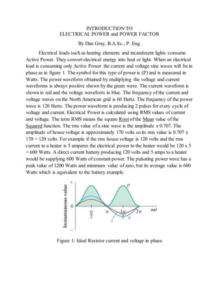
  • 1. INTRODUCTION TO ELECTRICAL POWER and POWER FACTOR By Dan Gray, B.A.Sc., P. Eng. Electrical loads such as heating elements and incandesent lights consume Active Power. They convert electrical energy into heat or light. When an electrical load is consuming only Active Power the current and voltage sine waves will be in phase as in figure 1. The symbol for this type of power is (P) and is measured in Watts. The power waveform obtained by multiplying the voltage and current waveforms is always positive shown by the green wave. The current waveform is shown in red and the voltage waveform in blue. The frequency of the current and voltage waves on the North American grid is 60 Hertz. The frequency of the power wave is 120 Hertz. The power waveform is producing 2 pulses for every cycle of voltage and current. Electrical Power is calculated using RMS values of current and voltage. The term RMS means the square Rootof the Mean value of the Squared function. The rms value of a sine wave is the amplitude x 0.707. The amplitude of house voltage is approximately 170 volts so its rms value is 0.707 x 170 = 120 volts. For example if the rms house voltage is 120 volts and the rms current to a heater is 5 amperes the electrical power to the heater would be 120 x 5 = 600 Watts. A direct current battery producing 120 volts and 5 amps to a heater would be supplying 600 Watts of constant power. The pulsating power wave has a peak value of 1200 Watts and minimum value of zero, but its average value is 600 Watts which is equivalent to the battery example. Figure 1: Ideal Resistor current and voltage in phase
  • 2. When a coil of wire (inductor) is connected to a sinusoidal voltage the current that flows will lag the voltage waveform as in Figure 2. Forthe ideal inductor with zero resistance the current lags the voltage wave by 90 degrees. The power waveform is the productof the voltage and current waves and has equal negative and positive areas under the power wave. The positive areas are times when the inductor absorbs energy and the negative areas are times when the inductor returns energy back to the energy sourcesuch as a generator. This type of power is called Inductive Reactive Power (symbol is QL) and is measured in Vars which is determined by multiplying the rms voltage and current. For example if the voltage is 120 volts and the current is 4 Amps the reactive power QL = 120 x 4 = 480Vars lagging. VAR is an acronym meaning Volt Amps Reactive. This type of power does not do any useful work but does require extra current to supply it to motor coils. Figure 2: Ideal Inductor current lags voltage by 90 degrees When a capacitor is connected to a sinusoidal voltage the current that flows will lead the voltage waveform as in Figure 3.Forthe ideal capacitor with zero resistance the current leads the voltage wave by 90 degrees. The power waveform is the productof the voltage and current waves and has equal negative and positive areas under the power wave. The positive areas are times when the capacitor absorbs energy and the negative areas are times when the capacitor returns energy back to the energy source. This type of power is called Capacitive Reactive Power (symbol is QC) and is measured in Vars and is determined by multiplying the rms voltage and current. For example if the voltage is 120 volts and the current is 3 Amps the reactive power QC = 120 x 3 = 360Vars leading. This type of power does not do any useful work but can be used to supply reactive power to a motor coil.
  • 3. Figure 3: Ideal Capacitor current leads voltage by 90 degrees A motor requires reactive power because of the magnetic field produced by the stator coils. The positive portion of the power wave is equal to the negative portion of the power wave so no active power is supplied to the ideal coil. This reactive power is measured in Vars and is an exchange of energy that is transmitted from the alternator to the motor load and then returns back to alternator and does no useful work but does require extra current flow in the transmission line. The current in the transmission line produces heat in the resistance of the line. The extra current required to supply reactive power increases transmission line power loss and also increases the voltage drop on the line which reduces the voltage at the load. The power flow to a motor consists of Active Power and Reactive Power. The electrical Active power supplied is converted to mechanical power to turn the motor shaft. Some power is lost due to rotor and stator heating, bearing and windage friction. The Reactive power oscillates between the motor and the source as it produces the magnetic field for the motor. Figure 4 is an example of motor current lagging the voltage by 45 degrees or π/4 radians.
  • 4. Figure 4: Motor current lagging voltage by 45 degrees. The Apparent power has units of Volt Amps (VA) and is determined using a right-angle triangle. The hypotenuse represents the Apparent power(S) and the Active(P) and Reactive(Q) powers are the other two sides of the triangle so that S2 = P2 + Q2. The angle Ɵ between S and P is the power factor angle and the ratio P/S = Cosine(Ɵ) and is the Power Factor.TheActive power P = S x cos(Ɵ)Watts and the Reactive power is Q = S x sin(Ɵ) Vars. Ɵ is also the phase angle between the current and voltage waves.
  • 5. A capacitor of the correctcapacitance value to make the Power factor equal to 1.0 can be put in parallel with the motor terminals and it will supply reactive power to the motor and the motor will supply reactive power to the capacitor. The capacitor and motor exchange reactive power with each other and the transmission line only has to supply true power current. The transmission line current is reduced and the power loss on the line is reduced. The voltage at the motor terminals will increase since the voltage drop on the line is reduced. The following diagram shows the effect of connecting a capacitor in parallel with an induction motor. The motor on the left is receiving 100 Amps from the 440 volt system. The Active power supplied is 35.2 KW which requires 80 Amps of in phase current. The Reactive power supplied is 26.4 KVars which requires 60 Amps of lagging current. The middle diagram shows the same motor with a 361.7 micro Farad capacitor connected in parallel with the motor terminals. This value of capacitance supplies 26.4 KVars of Reactive power to the motor and the 440 volt sourcedoes not have to supply any Vars to the motor. The source only has to supply the Active power of 35.2 KW with current of 80 Amps of in phase current. The capacitor supplies 60 Amps of lagging current to supply the required vars for the motor. Since the 440 volt source is supplying only Active power the Power Factor= 1.0 and the sourcecurrent and voltage are in phase. The right diagram shows the PF corrected to 0.9. The capacitor supplies 9.4 KVars and 21.4 Amps of lagging current to the motor and the source supplies 35.2 KW, 17.0 KVars, and 88.9 Amps lagging the voltage by 25.84 degrees. This current consists of 80 Amps of true power current and 38.6 Amps of reactive power current to make the total reactive current supplied to the motor equal to 60 Amps. Power factor correction reduces the current from the 440 volt supply, power loss and voltage drop in the resistance of the cable supplying the motor will be reduced which will increase voltage at the motor terminals and increase motor torque.