
Recommended
Recommended
More Related Content
What's hot
What's hot (19)
Similar to Voltage control of Induction Motor
Similar to Voltage control of Induction Motor (20)
More from Citharthan Durairaj
More from Citharthan Durairaj (13)
Recently uploaded
Recently uploaded (20)
Voltage control of Induction Motor
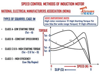
- 1. NATIONAL ELECTRICAL MANUFACTURERS ASSOCIATION (NEMA) TYPES OF SQUIRREL CAGE IM • CLASS A- LOW STARTING TORUE (Tst – A) • CLASS B – CONSTANT SPEED DRIVES • CLASS C & D– HIGH STARTING TORQUE (Tst – C & Tst – D) • CLASS E – HIGH EFFICIENCY (Low Slip Region) Tst - A Tst - B Tst - C Tst - D SPEED (N) TORQUE SPEED CONTROL METHODS OF INDUCTION MOTOR SLIP (S) 0 1 Ns 0 VERY IMPORTANT NOTE High rotor resistance High Starting Torque Tst Low Slip (for wide range Torque) High efficiency
- 2. SPEED CONTROL METHODS OF INDUCTION MOTOR 1) Line voltage control 2) Line frequency control Variable frequency constant voltage Voltage/Frequency control (V/F) Voltage Source Inverter fed induction motor drive Current Source Inverter fed induction motor drive 3) Rotor resistance control 4) Slip power recovery scheme Why Induction motor? Six Step Pulse Width Modulation (PWM) – Rugged construction (no commutators) & availability of solid state controllers Used only in slip ring induction motor
- 3. 1) LINE VOLTAGE CONTROL INDUCTION MOTOR FAN LOAD TORQUE SPEED Variable Three Phase Stator Voltage (Vs) • EASIEST METHOD • ECONOMICAL TORQUE SPEED 25% Vs 50% Vs 75% Vs 100% Vs N1 N2 N3 N4 NEMA CLASS D CAN BE SUITABLE TO GET WIDE SPEED RANGE SPEED RANGE Ns0 SPEED TORQUE
- 4. TORQUE- SPEED CHARACTERISTICS OF VOLTAGE CONTROL How to change the “voltage”? (Implementation) Method 1 Method 2 - Using “Auto transformer” - Variation is smooth - O/P -> Sinusoidal voltage - Using “Solid State Controllers” - O/P –> Non Sinusoidal !! - Input Filter required – Large Applns By changing the “Firing angle - alpha”
- 5. 2. Actual Rotor Speed N 4. Error = N*- N 5.Firing angle 6. Voltage Method 3 – Using Solid State Controllers -- Closed loop 1. Desired Rotor speed N* -+3. Error Generator “Used when Precise speed Control is required” Manual Speed setting Potentiometer! INPUT VOLTAGE OUTPUT VOLTAGE T1 T2 • Turn Off Time (T.Off) thinner • So AVG V (1/2 cycle)= greater! • Turn off time (T.Off) larger • So AVG V (1/2 cycle) = smaller! Controller Speed sensor g1 g2 A K AK + - + - - + T1 α 30 T.Off T2 α 180 +30 T1 T2 T.Off α 180 +60
- 6. TORQUE- SPEED CHARACTERISTICS OF VOLTAGE CONTROL • EASIEST • ECONOMICAL • INCREASE THE SPEED RANGE WITH CLASS D MOTORS • SLIP ∝ (Ns-N) IS HIGH @ LOW SPEEDS – SO, LOW EFFICIENCY NOTE “SYNCHRONOUS SPEED “Ns” IS NOT CHANGING” • FANS • PUMPS • CENTRIFUGAL DRIVES APPLICATIONS SLIP SPEED RANGE