1. RCP2 ROBO Cylinder
RCP2-GR3LM ROBO Cylinder 3-Finger Gripper Lever Type 80mm Width Pulse Motor
Series Type Encoder Motor Deceleration Ratio Stroke Compatible Controllers Cable Length Option
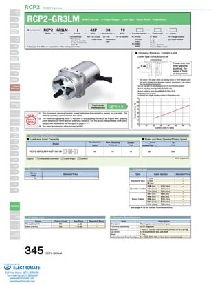
70
60
50
40
30
20
10
0
0 10 20
30 40 50 60 70
Current Limit (% ratio)
Gripping force (N)
■ Configuration: RCP2 GR3LM I 42P 30 19
(1) The maximum opening/closing speed indicates the operating speed on one side. The
relative operating speed is twice this value.
(2) The maximum gripping force is the sum of the gripping forces of all fingers with gripping
point distance of 10mm and no overhang distance. For the actual transportable work piece
weight, see explanation on the right, or page A-77.
(3) The rated acceleration while moving is 0.3G.
O I N
P
T
Notes on
Selection
Max. Gripping
Model Stroke
Force (N)
Legend: 1 Compatible controllers 2 Cable length 3 Options (Unit: degrees/s)
Stroke List 2 Cable List
Type Cable Symbol Standard Price
Standard Type
Special Lengths
Robot Cable
P (1m)
S (3m)
M (5m)
X06 (6m) ~ X10 (10m)
X11 (11m) ~ X15 (15m)
X16 (16m) ~ X20 (20m)
R01 (1m) ~ R03 (3m)
R04 (4m) ~ R05 (5m)
R06 (6m) ~ R10 (10m)
R11 (11m) ~ R15 (15m)
R16 (16m) ~ R20 (20m)
–
–
–
–
–
–
–
–
–
–
–
* See page A-39 for cables for maintenance.
3 Option List Actuator Specifications
Item Description
Worm gear + worm wheel gear
±0.01 degrees
1 degree or less per side (constantly pressed out by a spring)
0.15 degrees or less per side
1.1kg
0~40°C, 85% RH or less (non-condensing)
Drive System
Positioning Repeatability
Backlash
Lost Motion
Weight
Ambient Operating Temp./Humidity
Actuator Specifications
■ Lead and Load Capacity ■ Stroke and Maxi. Opening/Closing Speed
Deceleration
Ratio
30 51
(deg)
RCP2-GR3LM-I-42P-30-19- 1 - 2 - 3 19
Stroke
Deceleration Ratio
19
(deg)
30 200
10 –
■ Gripping Force vs. Current Limit
Lever Type (GR3LS/GR3LM)
F
L
* The values in the graph below are gripping forces at 10mm gripping point.
The actual gripping force decreases inversely proportional to the distance
from the opening/closing point.
You can calculate the actual gripping force by the following equation.
Actual gripping force (type S)=P×24/(L+14)
Actual gripping force (type M)=P×28.5/(L+18.5)
P=Gripping force on graph
L=Distance from finger mounting surface to the gripping point.
P. A-5 Technical
References
* Please note that,
when gripping
(pushing), the
speed is fixed
at 5 degrees/s.
Stroke
(deg) Standard Price
Name Option Code See Page Standard Price
FB
SB
→ A-26
→ A-36
Flange bracket
Shaft bracket
–
–
* See page Pre-35 for an explanation of the naming convention.
42P : 42 † size
Pulse motor
I: Incremental
* The Simple
absolute encoder
is also considered
type "I".
P1: PCON
RPCON
PSEL
P3: PMEC
PSEP
N : None
P : 1m
S : 3m
M : 5m
X□□ : Custom
R □□ : Robot cable
FB : Flange bracket
SB : Shaft bracket
30 : 1/30 19: 19 degrees
deceleration
ratio
345 RCP2-GR3LM
Slider
Type
Mini
Standard
Controllers
Integrated
Rod
Type
Mini
Standard
Controllers
Integrated
Table/Arm
/Flat Type
Mini
Standard
Gripper/
Rotary Type
Linear Servo
Type
Cleanroom
Type
Splash-Proof
Controllers
PMEC
/AMEC
PSEP
/ASEP
ROBO
NET
ERC2
PCON
ACON
SCON
PSEL
ASEL
SSEL
XSEL
Pulse Motor
Servo Motor
(24V)
Servo Motor
(200V)
Linear
Servo Motor
Sold & Serviced By:
ELECTROMATE
Toll Free Phone (877) SERVO98
Toll Free Fax (877) SERV099
www.electromate.com
sales@electromate.com
2. RCP2 ROBO Cylinder
For Special Orders P. A-9
36 78
2-ø3+0.03
Cable joint
connector*1
10+0.05
0
2 0.5
3-M5 (effective depth 7)
(same for back side) Flange plug (set screw M5 x 6)
4-M6 depth 12
(same for back side)
34
(same for back side)
1.5
64
ø3+0.05
-0.05
18
4-ø5.5
0
-0.05
ø75
0
1 Compatible Controllers
The RCP2 series actuators can operate with the controllers below. Select the controller according to your usage.
80
48
2-3+0.05
0 depth 3
Secure at least 100
0 depth 3
114
62
80
62
Mounting
surface
Mounting
surface
ø98
77
(23.5)
7
14°
120°
40.5
120°
ø75
4
12
14.5
ø62
7
4
10 0
10
9
2-M4
Mounting surface
(same for opposite side)
22
(136)
A
20
ø29
M8 (effective depth 4)
Home
Details of A
5°
Dimensions
* When homing, the actuator swings 1 degree past the home position before
returning. Therefore, please watch for any interference with the surrounding
objects.
*1 The motor-encoder cable is connected here. See page A-39 for details on
cables.
Weight (kg) 1.1
Name External View Model Description Max. Positioning Points Input Voltage Power Supply Capacity Standard Price See Page
Solenoid Valve Type
PMEC-C-42PI-NP-2-1 Easy-to-use controller, even for beginners
3 points
AC100V
AC200V
See P481 – → P477
PSEP-C-42PI-NP-2-0
Operable with same signal as solenoid valve.
Supports both single and double solenoid types.
No homing necessary with simple absolute type.
DC24V 2A max.
–
→ P487
Splash-Proof
Solenoid Valve Type
PSEP-CW-42PI-NP-2-0 –
Positioner Type PCON-C-42PI-NP-2-0
Positioning is possible for up to 512 points 512 points
–
→ P525
Safety-Compliant
Positioner Type
PCON-CG-42PI-NP-2-0 –
Pulse Train Input Type
(Differential Line Driver)
PCON-PL-42PI-NP-2-0
Pulse train input type with
differential line driver support
(−)
–
Pulse Train Input Type
(Open Collector)
PCON-PO-42PI-NP-2-0
Pulse train input type with
open collector support
–
Serial
Communication Type
PCON-SE-42PI-N-0-0 Dedicated to serial communication 64 points –
Field Network Type RPCON-42P Dedicated to field network 768 points – → P503
Program Control
Type
PSEL-C-1-42PI-NP-2-0
Programmed operation is possible
Operation is possible on up to 2 axes
1500 points – → P557
* This is for the single-axis PSEL.
* 1 is a placeholder for the power supply voltage (1: 100V, 2: 100~240V).
RCP2-GR3LM 346
Slider
Type
Mini
Standard
Controllers
Integrated
Rod
Type
Mini
Standard
Controllers
Integrated
Table/Arm
/Flat Type
Mini
Standard
Gripper/
Rotary Type
Linear Servo
Type
Cleanroom
Type
Splash-Proof
Controllers
PMEC
/AMEC
PSEP
/ASEP
ROBO
NET
ERC2
PCON
ACON
SCON
PSEL
ASEL
SSEL
XSEL
Pulse Motor
Servo Motor
(24V)
Servo Motor
(200V)
Linear
Servo Motor
Sold & Serviced By:
ELECTROMATE
Toll Free Phone (877) SERVO98
Toll Free Fax (877) SERV099
www.electromate.com
sales@electromate.com