Tampa BSides - Chef's Tour of Microsoft Security Adoption Framework (SAF)
SR60A Series Brushless Servo Amplifiers Guide
1. SR60A Series
SR60A SERIES BRUSHLESS SERVO AMPLIFIERS
Models: SR60A8*, SR60A40
Sold & Serviced By:
ELECTROMATE
Toll Free Phone (877) SERVO98
Toll Free Fax (877) SERV099
www.electromate.com
sales@electromate.com
FEATURES:
• Surface-mount technology
• Small size, low cost, ease of use
• Optical isolation, see block diagram
• DIP switch selectable modes:
current, resolver velocity
• Four quadrant regenerative operation
• Resolver interface for sinusoidal commutation
• Emulated encoder output
• Commutation Detection and Burst Mode
• Agency Approval:
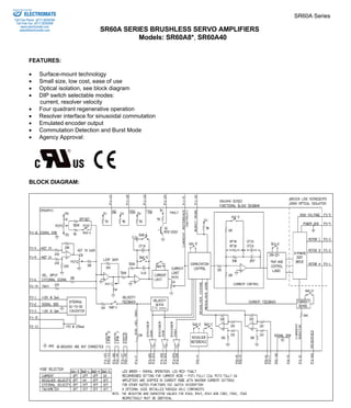
BLOCK DIAGRAM:
2. Sold & Serviced By:
ELECTROMATE
SR60A Series
Toll Free Phone (877) SERVO98
Toll Free Fax (877) SERV099
DESCRIPTION: The SR60A Series PWM servo amplifiers are designed to drive brushless motors with 3-phase sine
wave current. An on board digital controller generates the 3 phase sine wave signals from the resolver input. The
encoder emulation outputs (A, B and I) continuously produce signals equivalent to a 1024 line encoder. All models are
fully protected against over-voltage, under-voltage, over-current, over-heating and short-circuits. The SR60A series
interface with a digital controller or can be used as a stand-alone drive. Only a single unregulated DC power supply is
required. A red/green LED and a single digital output indicate operating status. Loop gain, current limit, input gain and
offset can be adjusted using 14-turn potentiometers. The offset adjusting potentiometer can also be used as an on-board
input signal for testing purposes when SW1 (DIP-switch) is ON.
SPECIFICATIONS:
www.electromate.com
sales@electromate.com
D-74
MODELS
POWER STAGE SPECIFICATIONS SR60A8* SR60A40
DC SUPPLY VOLTAGE 20-80 VDC 60 - 400 VDC
PEAK CURRENT (2 sec. max., internally limited) ± 60 A (42.4 Arms)
MAXIMUM CONTINUOUS CURRENT (internally limited) ± 30 A (21.2 Arms)
MINIMUM LOAD INDUCTANCE** 300 μH 600 μH
SWITCHING FREQUENCY 20 kHz nominal
HEATSINK (BASE) TEMPERATURE RANGE 0o to +65o C, disables if > 65o C
POWER DISSIPATION AT CONT. CURRENT 120 W 600 W
OVER-VOLTAGE SHUT-DOWN (self reset) 86 V 425 V
BANDWIDTH (load dependent) 2.5 kHz
MECHANICAL SPECIFICATIONS
POWER CONNECTOR: P3 Screw terminals
SIGNAL CONNECTORS: P1, P2 P1 is a 26 pin high density female D-sub connector and
P2 is a 15-pin high-density female D-sub connector.
SIZE
9.24 x 6.31 x 3.50 inches
234.7 x 160.2 x 88.9 mm
WEIGHT
5.64 lbs.
2.56 kg.
*Contact Factory regarding UL approval
** Low inductance motors require external inductors.
3. SR60A Series
D-75
Sold & Serviced By:
ELECTROMATE
Toll Free Phone (877) SERVO98
Toll Free Fax (877) SERV099
PIN FUNCTIONS:
www.electromate.com
sales@electromate.com
CONNECTOR PIN NAME DESCRIPTION / NOTES I/O
1 +10V @ 3 mA For customer use O
2 SIGNAL GND Reference ground SGND
3 -10V @ 3 mA For customer use O
4 +REF
Differential reference input, maximum ±15V, 20K input resistance I
5 -REF
6 Velocity Input Single ended reference input, external velocity signal, maximum ±15V, 10K
input resistance
I
7 Velocity Monitor 1 V = 1500 RPM O
8 Current Monitor This signal is proportional to the RMS current in the motor leads;
SR60A8, SR60A40: 1V = 8 Amps
O
9 Current Reference
This is the command signal to the internal current-loop. The maximum peak
current rating of the amplifier always equals 7.25 V at this pin.
SW1-3=ON, 7.25V=60 A; SW1-3=OFF, 7.25V=30 A.
O
10 Burst Mode Enable Pull to ground to enable. See Burst Mode below. I
11 Inhibit/Enable SW1-6 = ON Pull to ground to inhibit
SW1-6 = OFF pull to ground to enable I
12 +Inhibit/Enable I
13 -Inhibit/Enable
If SW1-6=ON, pull P1-12 and P1-13 to ground to inhibit (+) amplifier
output and P1-13 to inhibit (-) amplifier output.
If SW1-6=OFF, pull P1-12 and P1-13 to ground to enable (+) amplifier
output and P1-13 to enable (-) amplifier output.
These inputs will NOT cause a fault condition or a red LED. I
14 Fault (LED red)
TTL level output. Becomes high during output short circuit, over-voltage,
over temperature, inhibit, and during power-up reset. Fault condition
indicated by red LED.
O
15 +5V @ 250mA For customer use. Note: the total current on P1-15 and P2-13 combined
should not exceed 250 mA.
O
16 SIGNAL GND Reference ground SGND
17 Controller Power* Connected to P2-15. For customer use I
18 Controller Line 1* Connected to P2-10. For customer use I
19 Controller Line 2* Connected to P2-11. For customer use I
20 Encoder Channel A+
RS485 encoder output (1024 lines/rev) O
21 Encoder Channel A-Differential
22 Encoder Channel B+
23 Encoder Channel B-Differential
RS485 encoder output (1024 lines/rev) O
24 Index+
25 Index-
Differential RS485 encoder output O
P1
26 Reserved
NOTE: All circuits on connectors P1 and P2 are optically isolated fromall circuits on connector P3.
* No connection internal to the amplifier. See block diagram.
4. Sold & Serviced By:
ELECTROMATE
SR60A Series
Toll Free Phone (877) SERVO98
Toll Free Fax (877) SERV099
PIN FUNCTIONS:
www.electromate.com
sales@electromate.com
CONNECTOR PIN NAME DESCRIPTION / NOTES I/O
D-76
1 NC No Connection
2 NC No Connection
3 NC No Connection
4 REF+
5 REF-Differential
Output. Resolver Reference. See
SW2-2 for output parameters. O
6 SIN+
7 SIN- Differential Input. Resolver Sine I
8 COS+
Input. Resolver Cosine I
9 COS-Differential
10 Controller Line 1* Connected to P1-18. For customer use. O
11 Controller Line 2* Connected to P1-19. For customer use. O
12 Signal GND Reference ground SGND
13 +5V @ 250mA
For customer use. Note: the total current on P1-
15 and P2-13 combined should not exceed 250
mA.
O
14 TACH
Tachometer Input, 60 KΩ input resistance, ± 60 V
max. I
P2
15 Controller power* Connected to P1-17. For customer use. O
1 MOTOR A Motor phase A connection O
2 MOTOR B Motor phase B connection O
3 MOTOR C Motor phase C connection O
4 POWER GND Power ground PGND
P3
5 HIGH VOLTAGE DC power input I
NOTE: All circuits on connectors P1 and P2 are optically isolated fromall circuits on connector P3.
* No connection internal to the amplifier. See block diagram.
5. SR60A Series
D-77
Sold & Serviced By:
ELECTROMATE
Toll Free Phone (877) SERVO98
Toll Free Fax (877) SERV099
www.electromate.com
sales@electromate.com
SWITCH FUNCTIONS:
BANK 1
SETTING
SWITCH FUNCTION DESCRIPTION
ON OFF
1-1
Test / Offset controls the sensitivity of the
"offset" pot. This is used as an on-board
reference signal in test mode.
Test Offset
1-2 Current loop gain* Decrease Increase
1-3
Current scaling. When OFF, this increases
the sensitivity of the current sense thus
reducing both peak and continuous current
limit by 50%.
100%
50%
1-4 Continuous current reduction
Continuous / peak current
limit ratio is 50%
Continuous / peak current
limit ratio is 25%
1-5 Commutation Detection Detect phase angle. See Commutation Detection below.
1-6 INHIBIT/ENABLE P1-11, 12, 13 : INHIBIT P1-11, 12, 13 : ENABLE
* See item “6.3 Current Loop Adjustments” in section G for more information.
Units are shipped set for ½ current output via SW1-3=off and in the disabled state via SW1-6=off.
BANK 2
SETTING
SWITCH FUNCTION DESCRIPTION
ON OFF
2-1
Velocity feedback. This connects the
internally generated velocity signal from
the resolver.
On Off
2-2 Resolver Reference Voltage
4.00 Vrms
0.5 transformation ratio
4.25 Vrms
0.47 transformation ratio
2-3 Resolver Reference Frequency 5 kHz NA
2-4 Reserved
2-5
Loop integrator. This capacitor normally
ensures "error-free" operation in velocity
mode by reducing the error signal
(output of summing amplifier) to zero.
Disables the velocity /
voltage loop integrator
capacitor
Enables the velocity /
voltage loop integrator
2-6
Integrator capacitor. This adjusts the value
of the integrator capacitor in the velocity
mode.
Increase Decrease
Contact factory for additional resolver reference voltage and/or frequency options.
6. Sold & Serviced By:
ELECTROMATE
SR60A Series
Toll Free Phone (877) SERVO98
Toll Free Fax (877) SERV099
POTENTIOMETER FUNCTIONS:
www.electromate.com
sales@electromate.com
POTENTIOMETER DESCRIPTION TURNING CW
D-78
Pot 1
This potentiometer is the loop gain adjustment in the velocity
mode. Turn this pot fully ccw in current mode. Increases loop gain
Pot 2
Current limit. This potentiometer adjusts both the continuous
and peak current limit while maintaining a selected ratio. Increases current limit
Pot 3
Reference in gain. This potentiometer adjusts the ratio
between input signal and output variables (voltage, current,
and velocity).
Increases reference input
gain
Pot 4
Test / Offset. Used to adjust any imbalance in the input
signal or in the amplifier. When SW1-1 (DIP switch) is ON,
the sensitivity of this pot is greatly increased allowing it to be
used as an on-board signal source for testing purposes.
N/A
TEST POINTS FOR POTENTIOMETERS: See section "G".
OPERATING MODE SELECTION:
FEEDBACK MODE
The following operating modes can be selected by setting the DIP switches according to the following chart:
• Current mode
• Resolver velocity mode
• External velocity mode
• Tachometer mode
MODE SW1-1 SW1-2 SW1-3 SW1-4 SW1-5 SW1-6 SW2-1 SW2-2 SW2-3 SW2-4 SW2-5 SW2-6
Current Mode X X X X X X OFF X X X ON X
Resolver
Velocity Mode X X X X X X ON X X X OFF X
External
velocity mode X X X X X X OFF X X X OFF X
Tachometer
mode X X X X X X OFF X X X OFF X
X does not affect mode.
COMMUTATION DETECTION MODE (SW1-5):
In commutation detection mode the amplifier will automatically detect the optimum phase angle by performing a test
move while monitoring motor position. Phase-offset and pole-count are stored in non-volatile memory for further use. In
this mode the motor shaft MUST BE de-coupled from the load and free to move. It is also recommended to secure the
motor to avoid damage or injury. CAUTION: Sudden motion will occur in Commutation Detection Mode. Do not
activate commutation mode while the motor is attached to the load and do not touch the motor shaft during the
test move. To start commutation detection, follow the steps below.
1. Configure the amplifier for current mode (see table in block diagram)
7. SR60A Series
Sold & Serviced By:
ELECTROMATE
Toll Free Phone (877) SERVO98
Toll Free Fax (877) SERV099
2. Set the amplifier current limits to match the motor current specifications (see Current Limit Adjustments below).
D-79
www.electromate.com
sales@electromate.com
Failure to do so may severely damage the motor.
3. Apply a reference signal such that a current larger than the continuous current of the motor is commanded.
A. If the on-board test pot (Pot 4 with SW1-1 ON) is used as the reference signal, the pot must be turned
CCW from the middle (0V Command) of the 14-turn pot.
B. If an external reference signal is used, this command signal must be a positive command (i.e. positive
voltage into +REF must be positive referenced to Signal GND).
4. Power up the amplifier:
A. in a disabled state (via enable/disable input P1-11 or DIP-switch SW1-6),
B. with SW1-5 OFF,
C. and with P1-10 (Burst Mode) open.
5. Once the amplifier is fully powered (with LED red), set switch SW1-5 ON.
6. Enable the amplifier (the LED will remain red).
7. Pull P1-10 (Burst Mode) to ground. The LED will turn green. At this time the motor will make one and a half
revolutions CW and one and a half revolutions CCW. If no motion occurs, power down and repeat from step 1.
8. Upon completion the amplifier will automatically disable (red LED).
9. To complete detection mode:
A. power off the amplifier,
B. set switch SW1-5 OFF,
C. and release P1-10 (Burst Mode).
D. remove command signal (set Pot 4 to middle if it was used in step 3A)
10. The amplifier is now operational.
BURST MODE (Pin P1-10)
In Burst Mode the amplifier will send an encoder pulse stream to the motion controller equal to the amount of pulses
between the resolver datum and the actual motor position. This allows the motion controller to register the absolute motor
position (within one motor revolution). The Burst Mode sequence is as follows:
5. Disable the amplifier.
6. Pull Burst Mode input to ground (can be done immediately after amplifier disable).
7. Upon Burst Mode input pull-down, the amplifier will first send a single index channel pulse and then 2 channel A and
2 channel B pulses (8 counts). The Burst Mode input must be pulled down for at least 2.1 milliseconds to ensure this
initial stream.
8. Upon Burst Mode input release, the amplifier will stream the appropriate amount of pulses (from datum to actual
position) with channel A leading channel B. This stream will complete in 15 milliseconds (channel line width is 3.4
microseconds).
Caution: motor shaft movement during Burst Mode will not be registered! The motor shaft must remain in position during
Burst Mode in order to work properly!
APPLICATION NOTE: For proper operation, P1-6 and P2-14 must be connected to the signal ground if they are not
being used.
SET-UP: See section "G" for engineering and installation notes.
8. Sold & Serviced By:
ELECTROMATE
SR60A Series
Toll Free Phone (877) SERVO98
Toll Free Fax (877) SERV099
CURRENT LIMIT ADJUSTMENTS:
These amplifiers feature separate peak and continuous current limit adjustments. The current limit adjustment Pot 2
adjusts both peak and continuous current limit at the same time. It has 12 active turns, one inactive turn at each end and
is approximately linear. Thus, to adjust the current limit turn the potentiometer counter-clockwise to zero, then turn
clockwise to the appropriate value. In many applications it is sufficient to use only the DIP-switches for current limit
adjustments. SW1-3 reduces both peak and continuous current limit by 50% when OFF. SW1-4 reduces only the
continuous current limit by 50% when OFF:
www.electromate.com
sales@electromate.com
D-80
SW1-4 CONTINUOUS / PEAK CURRENT LIMIT RATIO
ON 50%
OFF 25%
P1-9 is the input to the internal current amplifier power stage. Since the output current is proportional to P1-9, the
adjusted current limit can easily be observed at this pin without connecting the motor. Note that a command signal
must be applied to the reference inputs to obtain a reading on P1-9. The maximum peak current value equals 7.25 V at
this pin and the maximum continuous current value equals 3.63 V at this pin. If SW1-3=ON, peak rated amplifier
current = 7.25 V. If SW1-3=OFF, ½ peak rated amplifier current =7.25 V. Example: using the SR60A40 with SW1-
3=ON, 60A=7.25V and with SW1-3=OFF, 30A=7.25V.
The actual output current can be monitored at pin P1-8.
ORDERING INFORMATION:
Models: SR60A8X, SR60A40X
X indicates the current revision letter.
TYPICAL SYSTEM WIRING: See section "G".
The resolver connections must be made with individually shielded, twisted wire pairs for proper operation.
MATING CONNECTORS:
Manufacturer: AMP (Tel: 1-800-522-6752)
Part numbers:
15 Pin plug 748364-1
26 Pin plug 748365-1
Pins 748333-2
Shell Kit (plastic with metal coating)
15 Pin 748677-1
26 Pin 748677-2
MOUNTING DIMENSIONS: See page F-17.