
Recommended
More Related Content
What's hot
What's hot (20)
Similar to Million square foot building lutes aehs epa workshop ssda community leader-final
Similar to Million square foot building lutes aehs epa workshop ssda community leader-final (20)
More from Chris Lutes
More from Chris Lutes (20)
Recently uploaded
Recently uploaded (20)
Million square foot building lutes aehs epa workshop ssda community leader-final
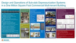
- 1. Full Building System System Summary A total of 61 extraction points spaced approximately 120 feet apart along the building’s existing structural steel A total of 91 sub-slab monitoring points throughout the facility System components include: • Four 150 horsepower blowers • Moisture separator • Condensate storage tank • Heat exchanger • Chilled water system • Two 10,000 pound carbon vessels • Emergency generator • Fully integrated System Control Center Summary of System Performance The system meets or exceeds all design objectives. • Sub-slab pressure differentials of -0.004 or greater – often by an order of magnitude • Discharge concentrations are below the detection limit of the analytical method • Carbon usage rates of 10 pounds per day • Reliable and trouble-free operations from system components since being placed into service Design and Operations of Sub-slab Depressurization Systems in a One Million Square Foot Commercial Multi-tenant Building Chris Engler, Rachel Saari, Nadine Weinberg and Chris Lutes (ARCADIS) Stewardship and Monitoring SSDS System Operations and Stewardship • Quarterly indoor air sampling • Continuous pressure communications monitoring to confirm the extent of the vacuum under the slab also known as the ROI • Continuous monitoring of operational parameters (i.e., flow and pressure) at each extraction point. Data are recorded and alarm set points will notify system operators of changes in operation • Quarterly reporting of system operation to the State Timeline and Overview 2006: State releases guidance for indoor and sub-slab vapor concentrations 2007: Indoor air/sub-slab sampling begins A. March 2007: 19 sub-slab soil gas, 27 indoor air samples B. October 2007: four sub-slab soil gas samples C. December 2007: 25 sub-slab soil gas, 33 indoor air samples 2008: Localized eastern SSDS installed D. January 2008: 13 indoor air samples E. March 2008: 42 sub-slab soil gas and 13 indoor air samples F. September – November 2008: 52 sub-slab soil gas and 24 indoor air samples 2009: Localized central SSDS installed 2009: Site-wide SSDS design alternatives evaluated G. January 2009: 46 sub-slab soil gas, 38 indoor air samples H. March 2009: 22 sub-slab soil gas, 28 indoor air samples I. December 2009 – January 2010: 85 sub-slab soil vapor, 89 indoor air samples 2010: Final approval of Conceptual SSDS design by the State 2010: Western SSDS installation in main building began J. March 2010: 12 sub-slab soil vapor, 18 indoor air samples 2011: Eastern SSDS installation in main building began K. March 2011: 68 sub-slab soil vapor, 68 indoor air samples 2012: Construction began for equipment/control building L. February – March 2012: 76 sub-slab soil vapor, 95 indoor air samples 2013: SSDS construction complete; System Operational M. February – March 2013: 79 sub-slab soil vapor, 98 indoor air samples Year Installed Time to Design/Install Coverage (ft2) Horsepower Horsepower per ft2 Localized Eastern System 2008 5 months 24,000 2.5 1/10,000 Localized Central System 2009 1 months 50,000 5 1/10,000 Full Building Permanent System 2013 3 years 1,000,000 225* 2.25/10,000 * The system has the capacity to run at 450 horsepower, it is currently operating at 225 horsepower Localized Eastern System • Covers approximately 24,000 ft2 • 2.5 horsepower blower Localized/Mobile Central System • Covers approximately 50,000 ft2 • 5 horsepower blower Interim and newly expanded sub-slab vacuum system. Extracts vapors from beneath the entire building and pipes them to the garage where they are treated. Clean air is released. Preparation for Installation Installation Typical Roof Top Pipe System Underground Pipe Installation Construction of Equipment Building SSDS Risers & Enclosures SSDS Extraction and Monitoring Points SSDS Sub Slab Pressure Contours during Startup 2007 2008 20112010 20122009 A B C D E F G H I J K 2013 L M Sealing expansion joints up to 2" wide provided considerable improvement in SSD performance Continuous Monitoring Point Detail Notes: 1. The goal of the sub-slab depressurization system is to maintain a minimum of -0.004 inches water column (in.w.c.) differential pressure in the target area. 2. Differential pressure refers to the difference in air pressure recorded across the building’s concrete floor slab. Measurements above the concrete floor slab are taken within one foot above the finished floor of the building. A positive differential pressure value indicates that air pressure under the floor slab is higher than air pressure above the floor slab; a negative differential pressure indicates that the air pressure under the floor slab is lower than the air pressure above the floor slab. Differential pressure measurements are collected using continuous logging micro-manometers that continuously record the “high” and “low” differential pressure across the floor slab during a 24-hour monitoring period.