Mass Transfer Principles for Vapor-Liquid Unit Operations (3 of 3)

The Principles required to understand Distillation, Absorption, Stripping, Flashing, Gas Treating, Scrubbing and more! Introduction: This course covers all the theory required to understand the basic principles behind Unit Operations that are based on Mass Transfer. Most of these Unit Operations (Equipments) are used in Process Separation Technologies in the Industry.Common examples are Distillation, Absorption and Scrubbing. This course is required for the following: Flash Distillation Gas Absorption & Stripping Simple Distillation Batch Distillation Binary Distillation Fractional Distillation Scrubbers Gas Treating Sprayers / Spray Towers Bubble Columns / Sparged Vessels Agitation Vessels Packed Towers Tray Towers We will cover: Mass Transfer Basics Diffusion, Convection Flux & Fick's Law The Concept of Equilibrium & Phases Gibbs Phase Rule Vapor Pressure Equilibrium Vapor-Liquid Diagrams (T-xy, P-xy, XY) Equilibrium Curves Dew Point, Bubble Point Volatility (Absolute & Relative) K-Values Ideal Cases vs. Real Cases Henry's Law Raoult's Law Deviations of Ideal Cases (Positive and Negative) Azeotropes Solubility of Gases in Liquids Interphase Mass Transfer and its Theories Two Film Theory Mass Transfer Coefficients (Overall vs Local) Getting Vapor-Liquid and Solubility Data Solved-Problem Approach: All theory is backed with: Exercises Solved problems Proposed problems Homework Case Studies Individual Study At the end of the course: You will be able to understand the mass transfer concepts behind various Unit Operations involving Vapor - Liquid Interaction. You will be able to apply this theory in further Unit Operations related to Mass Transfer Vapor - Liquid, which is one of the most common interactions found in the industry. About your instructor: I majored in Chemical Engineering with a minor in Industrial Engineering back in 2012. I worked as a Process Design/Operation Engineer in INEOS Koln, mostly on the petrochemical area relating to naphtha treating. There I designed and modeled several processes relating separation of isopentane/pentane mixtures, catalytic reactors and separation processes such as distillation columns, flash separation devices and transportation of tank-trucks of product.

Recommended
Recommended
More Related Content
What's hot
What's hot (20)
Similar to Mass Transfer Principles for Vapor-Liquid Unit Operations (3 of 3)
Similar to Mass Transfer Principles for Vapor-Liquid Unit Operations (3 of 3) (20)
More from Chemical Engineering Guy
More from Chemical Engineering Guy (20)
Recently uploaded
Recently uploaded (20)
Mass Transfer Principles for Vapor-Liquid Unit Operations (3 of 3)
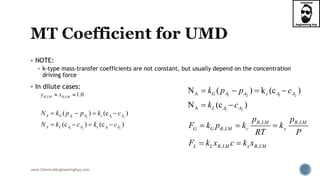
- 1. www.ChemicalEngineeringGuy.com NOTE: k-type mass-transfer coefficients are not constant, but usually depend on the concentration driving force In dilute cases: 1 2 1 2 1 2 1 2 ( ) (c ) (c ) (c ) A G A A c A A A L A A c A A N k p p k c N k c k c 1 2 1 2 1 2 A A N ( ) k (c ) N (c ) G A A c A A L A A k p p c k c , , , , , B LM B LM G G B LM c y L L B LM x B LM p p F k p k k RT P F k x c k x , , 1.0B LM B LMy x
- 2. www.ChemicalEngineeringGuy.com Blood oxygenators are used to replace the human lungs during open-heart surgery. To improve oxygenator design, you are studying mass transfer of oxygen into water at 310 K in one specific blood oxygenator. Correlated values of the MTC are A) Calculate the corresponding mass-transfer coefficient based on the mole fraction of oxygen in the liquid. Example 2.1 Mass-Transfer Coefficients in a Blood Oxygenator. Principles and Modern Applications of Mass Transfer Operations, Jaime Benitez, 2nd Edition 5 3.3 10 /MTC x m s Do you need the Full Version? Contact me if needed! Contact@ChemicalEngineeringGuy.com https://courses.chemicalengineeringguy.com/courses You can also check out more content here: My Youtube Channel My Fan Page The LinkedIn My website:
- 3. www.ChemicalEngineeringGuy.com A) Calculate the corresponding mass-transfer coefficient based on the mole fraction of oxygen in the liquid. Interpretation: First, verify which type of units / type of MTC is given Verify the type of process (UMD/EMD/OTHER) Calculate the required MTC in mol fraction of Oxygen. Do you need the Full Version? Contact me if needed! Contact@ChemicalEngineeringGuy.com https://courses.chemicalengineeringguy.com/courses You can also check out more content here: My Youtube Channel My Fan Page The LinkedIn My website:
- 4. www.ChemicalEngineeringGuy.com Assumptions: Neglect evaporation of water Diffusion of A (oxygen) takes place Stagnant B (water). Assume Dilute solution, since the solubility of oxygen in water at 310 K is extremely low, If this is true (dilute solution): k-type coefficients is appropriate.
- 5. www.ChemicalEngineeringGuy.com Solution The MTC value must be diluted, and valid for UMD, as it is the only species being diffused. This must be k-type value This is specified for the liquid so, kL We need to change form kL to kx. From previous work (actually for any UMD Case) 5 5 3.3 10 / 3.3 10 /L MTC x m s k x m s x Lk k c Do you need the Full Version? Contact me if needed! Contact@ChemicalEngineeringGuy.com https://courses.chemicalengineeringguy.com/courses You can also check out more content here: My Youtube Channel My Fan Page The LinkedIn My website:
- 6. www.ChemicalEngineeringGuy.com For this, we need concentration of the mixture. The concentration for any mixture: Since this is very dilute, assume: We know the density of water in mass per volume… Change to mol per volume x Lk k c 3 993 993 18 55.2 55.2 / mix mix g Lwater g mix mol mol Lwater mix mol c vol mass mol MW gmass mol MWc c kmol m vol L L mix mix mol c vol mix solvent mix solvent mol mol vol vol
- 7. www.ChemicalEngineeringGuy.com Now, 3 2 2 5 m 2 (3.3 10 )(55.2 ) 0.018216 1.8 10 kmol m s x L kmol kmol m s x s m x k k c k x k x Do you need the Full Version? Contact me if needed! Contact@ChemicalEngineeringGuy.com https://courses.chemicalengineeringguy.com/courses You can also check out more content here: My Youtube Channel My Fan Page The LinkedIn My website:
- 8. www.ChemicalEngineeringGuy.com A gas absorber is used to remove ammonia from air by scrubbing the gas mixture with water at 300 K and 1 atm. T=300K, P = 1 atm At a certain point in the absorber: the ammonia mole fraction in the bulk of the gas phase is 0.80 while the corresponding interfacial ammonia gas-phase concentration is 0.732. The ammonia flux at that point is measured as Evaporation of water can be neglected A) Calculate the mass-transfer coefficient in the gas phase at that point in the equipment. Example 2.2 Mass-Transfer Coefficient in a Gas Absorber. Principles and Modern Applications of Mass Transfer Operations, Jaime Benitez, 2nd Edition 2 4 4.3 10 kmol m s x
- 9. www.ChemicalEngineeringGuy.com Analysis: We are given concentrations in mol fraction of bulk-interphases The rate is given (that’s not common) Assumptions: Diffusion of ammonia through water Water is stagnant Non-dilute case! Do not use k-type coefficients! Use: 2 1 1 ln 1 A A G A y N F y Do you need the Full Version? Contact me if needed! Contact@ChemicalEngineeringGuy.com https://courses.chemicalengineeringguy.com/courses You can also check out more content here: My Youtube Channel My Fan Page The LinkedIn My website:
- 10. www.ChemicalEngineeringGuy.com The ammonia flux is from the bulk of the gas phase to the interface yA1 = 0.800 and yA2 = 0.732 2 1 2 2 1 2 4 4 1 ln 1 4.3 10 1 0.7321 lnln 1 0.801 1.47 10 A A G A kmol m sA G A A kmol G m s y N F y xN F y y F x
- 11. www.ChemicalEngineeringGuy.com Only valid for: EMD UMD Relations between Mass Transfer Coefficients (MTC) Phase EMD UMD Units Gas Gas Gas Liquid Liquid Conversion 'A G AN k p 'A y AN k y 'A c AN k c A G AN k p A y AN k y A c AN k c 2 mol m s Pa 2 . mol m s mol frac 2 / . mol m s mol vol 'A L AN k c 'A x AN k x A L AN k c A x AN k x 2 . mol m s mol frac 2 / . mol m s mol vol ' ' 'LM LMx B L B L L xMWF k x k x k c k k
- 12. www.ChemicalEngineeringGuy.com So far, Mass Transfer coefficients discussed are all based on: unit surface of contact between the phases They are expressed as But in most of the widely used industrial mass transfer equipment like the packed or plate columns: the interfacial area of contact between the phases cannot be measured. moles unit time unit area unit driving force Do you need the Full Version? Contact me if needed! Contact@ChemicalEngineeringGuy.com https://courses.chemicalengineeringguy.com/courses You can also check out more content here: My Youtube Channel My Fan Page The LinkedIn My website:
- 13. www.ChemicalEngineeringGuy.com In order to overcome this difficulty, volumetric mass transfer coefficients are generally used for calculating the rate of mass transfer. Both mass transfer coefficient and specific surface (m2/m3) of packing depend on: Type of Packing (configuration) Size of packing Flow rates of the concerned fluids
- 14. www.ChemicalEngineeringGuy.com They can be combined into a single product to provide mass transfer coefficient on volumetric basis. Thus, for transfer of a component within the gas phase, the mass flux and the rate equation may be written as: Where, NAa = mass flux per unit volume of the equipment kya = volumetric mass transfer coefficient in the gas phase moles/(unit time) (unit volume) (unit mole fraction) kxa = volumetric mass transfer coefficient in the liquid phase moles/(unit time) (unit volume) (unit mole fraction) ( ) (x ) G i L A y A A A x Ai A N a k a y y N a k a x
- 15. www.ChemicalEngineeringGuy.com Recall the Heat Transfer – Mass Transfer Analogy These are useful in understanding the underlying transport phenomena and as a satisfactory means of predicting behavior of systems for which limited quantitative data exist. Many of these coefficients have been derived by analogy with heat transfer Do you need the Full Version? Contact me if needed! Contact@ChemicalEngineeringGuy.com https://courses.chemicalengineeringguy.com/courses You can also check out more content here: My Youtube Channel My Fan Page The LinkedIn My website:
- 16. www.ChemicalEngineeringGuy.com In order to get these: The dimensionless groups of heat transfer are replaced by the corresponding groups of mass transfer.
- 17. www.ChemicalEngineeringGuy.com Reynolds Schmidt Prandtl Sherwood Nusselt Stanton Peclet Fourier Grashof Colburn Lewis Heat Trasfer Mass Transfer Related Dimensionless Numbers & Anologies Pr pC k Re vl Re vl Sc ABD ' , , ,LM LMG B c B y AB AB AB AB k p RTl k p l k RTlFl Sh cD PD PD PD hl N k 3 2D gl Gr ReD AB lv Pe Sc D RePr p H C lv Pe k 3 2 2H gl T Gr Re D D Sh Sh F St Sc Pe cv RePr H H p Nu Nu h St Pe C v 2/3 D Dj St Sc 2/3 PrH Hj St Do you need the Full Version? Contact me if needed! Contact@ChemicalEngineeringGuy.com https://courses.chemicalengineeringguy.com/courses You can also check out more content here: My Youtube Channel My Fan Page The LinkedIn My website:
- 18. www.ChemicalEngineeringGuy.com Conditions: 1. The flow conditions and geometry must be the same. 2. Most heat-transfer data are based on situations involving no mass transfer. Use of the analogy would then produce mass-transfer coefficients corresponding to no net mass transfer, in turn corresponding most closely to: Sherwood numbers are commonly written in terms of any of the coefficients BUT: when derived by replacement of Nusselt numbers for use where the net mass transfer is not zero they should be taken as and the “F” used in: 2 1 ln A A c A c A A c A c N F ' ’ ’G c yk k or k F AB Fl cDSh
- 19. www.ChemicalEngineeringGuy.com Common analogies: Reynolds Analogy Chilton Colburn Analogy As in other systems, Chilton–Colburn analogy holds very well in single-phase flow through packed beds: jD and jH have been found to be essentially equal for the same bed geometry and flux conditions. In many cases: mass transfer coefficient can be estimated from heat transfer data. See Mass Transfer Coefficient correlation for packed beds
- 20. www.ChemicalEngineeringGuy.com Check out this vid: https://www.youtube.com/watch?v=7YlQ_4jL_gs
- 21. www.ChemicalEngineeringGuy.com Do you need the Full Version? Contact me if needed! Contact@ChemicalEngineeringGuy.com https://courses.chemicalengineeringguy.com/courses You can also check out more content here: My Youtube Channel My Fan Page The LinkedIn My website:
- 22. www.ChemicalEngineeringGuy.com Mass transfer coefficients (MTCs) are not physical properties like the diffusion coefficient. They differ from case to case and even within a system, depending on their definition. Experimental data are usually obtained by blowing gases over various shapes wet with evaporating liquids, or causing liquids to flow past solids which dissolve.
- 23. www.ChemicalEngineeringGuy.com Extensive data have been obtained for the transfer of mass between a moving fluid and certain shapes, such as: flat plates, spheres and cylinders. fluid flow through a packed bed of particles, gas bubbles rising in a tank, falling films, flow over surfaces and within tubes The techniques include: sublimation of a solid vapourization of a liquid into a moving stream of air the dissolution of a solid into water Dissolution of gases in liquids Do you need the Full Version? Contact me if needed! Contact@ChemicalEngineeringGuy.com https://courses.chemicalengineeringguy.com/courses You can also check out more content here: My Youtube Channel My Fan Page The LinkedIn My website:
- 24. www.ChemicalEngineeringGuy.com These data have been correlated in terms of dimensionless parameters and the equations obtained are used to estimate the mass transfer coefficients in other moving fluids and geometrically similar surfaces. Do you need the Full Version? Contact me if needed! Contact@ChemicalEngineeringGuy.com https://courses.chemicalengineeringguy.com/courses You can also check out more content here: My Youtube Channel My Fan Page The LinkedIn My website:
- 25. www.ChemicalEngineeringGuy.com Average, rather than local, mass-transfer coefficients are usually obtained In most cases, the data are reported in terms of the k-type coefficients applicable to the binary systems used with NB = 0. Typically, there are no details concerning the actual concentrations of solute during the experiments. Fortunately, the experimental concentrations are usually fairly low, so that if necessary, conversion of the data to the corresponding F is possible by taking: 1LMBp P 1LMBx Typically valid when solvent >> solute Do you need the Full Version? Contact me if needed! Contact@ChemicalEngineeringGuy.com https://courses.chemicalengineeringguy.com/courses You can also check out more content here: My Youtube Channel My Fan Page The LinkedIn My website:
- 26. www.ChemicalEngineeringGuy.com Typical Mass Transfer Correlations Do you need the Full Version? Contact me if needed! Contact@ChemicalEngineeringGuy.com https://courses.chemicalengineeringguy.com/courses You can also check out more content here: My Youtube Channel My Fan Page The LinkedIn My website:
- 27. www.ChemicalEngineeringGuy.com Typical Mass Transfer Correlations Do you need the Full Version? Contact me if needed! Contact@ChemicalEngineeringGuy.com https://courses.chemicalengineeringguy.com/courses You can also check out more content here: My Youtube Channel My Fan Page The LinkedIn My website:
- 28. www.ChemicalEngineeringGuy.com Mass Transfer in Flow Past Flat Plates Mass Transfer in Fluids Flowing Through Pipes* Mass Transfer Through Packed Bed* Mass Transfer Coefficient for Flow Past a Solid Sphere Mass Transfer in Flow Normal to a Single Cylinder Mass Transfer in the Neighbourhood of a Rotating Disk Mass Transfer to Drops and Bubbles*
- 29. www.ChemicalEngineeringGuy.com Fluids moving through pipes are used extensively in the industry. Many materials will mix inside a pipe regardless of the operation. Correlations for mass transfer inside pipes are similar in nature to those in heat transfer. For laminar flow: Sherwood number shows the same trend: As Nusselt number with a limiting value of 3.66 for very long pipes. For short pipes: Sherwood number varies as one-third power of flow rate.
- 30. www.ChemicalEngineeringGuy.com In view of inadequate data however, it has not been possible to develop working equations for mass transfer coefficient in laminar flow through pipes. Several authors have studied gas side coefficients for mass transfer between liquids and gases in wetted wall columns. Most of their data agree approximately with the following equation suggested by Gilliland and Sherwood (1934) Its based on 400 tests Test: Evaporation of water + eight other organic liquids into air flowing Through a wetted wall column of 2.54 cm internal diameter and 117 cm long Do you need the Full Version? Contact me if needed! Contact@ChemicalEngineeringGuy.com https://courses.chemicalengineeringguy.com/courses You can also check out more content here: My Youtube Channel My Fan Page The LinkedIn My website:
- 31. www.ChemicalEngineeringGuy.com We get: kC = gas-side mass transfer coefficient based on log-mean driving forces at two ends of the column, cm/s Re = air stream Reynold’s number based on velocity of air relative to the pipe wall. For engineering calculations, the following equation of Johnstone and Pigford (1942) may be used Where, Re′ = Reynolds number based on gas velocity relative to the liquid surface 3,000 < Re′ < 40,000 Sc lies between 0.5 and 3.0. 0.83 0.44 ' 0.023ReLMBc AB pk d Sc D P 0.23 0.0328(Re')Dj Heat Trasfer Mass Transfer Related Dimensionless Numbers & Anologies Pr pC k Re vl Re vl Sc ABD ' , , ,LM LMG B c B y AB AB AB AB k p RTl k p l k RTlFl Sh cD PD PD PD hl N k 3 2D gl Gr ReD AB lv Pe Sc D RePr p H C lv Pe k 3 2 2H gl T Gr Re D D Sh Sh F St Sc Pe cv RePr H H p Nu Nu h St Pe C v 2/3 D Dj St Sc 2/3 PrH Hj St
- 32. www.ChemicalEngineeringGuy.com Estimation of mass transfer coefficient of fluid flowing through a pipe from Gilliland’s equation Estimate the value of the mass transfer coefficient kG for: The absorption of ammonia by an acid from a turbulent air-NH3 stream Its moving velocity is 3 m/s through Operation counter-current wetted wall tube of 25 mm id. The temperature and pressure are 38°C and 101.3 kN/m2, respectively. The inlet gas contains 10% NH3 by volume The exit gas contains 1% NH3 by volume. EXAMPLE 3.5 Mass-Transfer-Principles- and-Operations-de-Sinha
- 33. www.ChemicalEngineeringGuy.com From databases: Analysis: Clearly, we can use Gilliland equation. EXAMPLE 3.5 Mass-Transfer-Principles- and-Operations-de-Sinha 3 3 5 5 2 1.15 1.85 10 2.4 10 / kg gas m kg msgas NH Air x D x m s Do you need the Full Version? Contact me if needed! Contact@ChemicalEngineeringGuy.com https://courses.chemicalengineeringguy.com/courses You can also check out more content here: My Youtube Channel My Fan Page The LinkedIn My website:
- 34. www.ChemicalEngineeringGuy.com Solution Verify that the operation is within the ranges: EXAMPLE 3.5 Mass-Transfer-Principles- and-Operations-de-Sinha 3 2 3 5 5 5 2 (1.14 )(3m/ s)(0.025m) Re 4620 1.85 10 1.85 10 (1.14 )(2.4 1 0.6761 0 / ) 6 kg i m kg m s kg ms kg AB m vDvl x x Sc D x m s Heat Trasfer Mass Transfer Related Dimensionless Numbers & Anologies Pr pC k Re vl Re vl Sc ABD ' , , ,LM LMG B c B y AB AB AB AB k p RTl k p l k RTlFl Sh cD PD PD PD hl N k 3 2D gl Gr ReD AB lv Pe Sc D RePr p H C lv Pe k 3 2 2H gl T Gr Re D D Sh Sh F St Sc Pe cv RePr H H p Nu Nu h St Pe C v 2/3 D Dj St Sc 2/3 PrH Hj St 3,000 < Re′ < 40,000 0.5 < Sc < 3.0. 0.83 0.44 ' 0.023ReLMBc AB pk d Sc D P Do you need the Full Version? Contact me if needed! Contact@ChemicalEngineeringGuy.com https://courses.chemicalengineeringguy.com/courses You can also check out more content here: My Youtube Channel My Fan Page The LinkedIn My website:
- 35. www.ChemicalEngineeringGuy.com Now, we have Re, Sc, and all other data BUT pressures: Calculate Pressure of A: Calculate Pressure of B: 0.83 0.44 ' 0.023ReLMBc AB pk d Sc D P 1 1 2 2 ' ' 101.3 10.13 91.17 ' ' 101.3 10.13 100.29 B T A B T A p P p kPa p P p kPa 1 1 2 2 ' (0.10)(101.3 ) 10.13 ' (0.01)(101.3 ) 1.013 A A T A A T p y P kPa kPa p y P kPa kPa EXAMPLE 3.5 Mass-Transfer-Principles- and-Operations-de-Sinha
- 36. www.ChemicalEngineeringGuy.com Calculate log mean. pressure of B: Now, solve for kc: EXAMPLE 3.5 Mass-Transfer-Principles- and-Operations-de-Sinha 2 1 2 1 ( ' ' ) (100.29 91.17) p' 95.6 100.29' lnln 91.17' LM B B B B B p p kPa p p 0.83 0.44 0.83 0.44 ' 0.023Re ' 0.023Re LM LM Bc AB B AB c pk d Sc D P p D k Sc P d Do you need the Full Version? Contact me if needed! Contact@ChemicalEngineeringGuy.com https://courses.chemicalengineeringguy.com/courses You can also check out more content here: My Youtube Channel My Fan Page The LinkedIn My website:
- 37. www.ChemicalEngineeringGuy.com Now, substitute data: Now, for kG 0.83 0.44 5 2 0.83 0.44 ' 0.023Re 95.67 2.4 10 / 0.023(4621) (0.676) 101.3 0.025 0.02167 LMB AB c c c p D k Sc P d kPa x m s k kPa m k 23 60.02167 8.38 10 8.314 (311 ) c G m s kmol G s m kPam kPa kmolK k k RT k x K
- 38. www.ChemicalEngineeringGuy.com Recall from the “Mass Transfer” Analogies with Heat Transfer that: As in other systems, Chilton–Colburn analogy holds very well in single- phase flow through packed beds: jD and jH have been found to be essentially equal for the same bed geometry and flux conditions. In many cases: mass transfer coefficient can be estimated from heat transfer data. This is a specific case in which jD = jH Do you need the Full Version? Contact me if needed! Contact@ChemicalEngineeringGuy.com https://courses.chemicalengineeringguy.com/courses You can also check out more content here: My Youtube Channel My Fan Page The LinkedIn My website:
- 39. www.ChemicalEngineeringGuy.com Mass transfer to and form packed beds occur often in processing operations: Drying, adsorption, desorption of gas Mass transfer from gases and liquids to catalyst particles. Using a packed bed a large amount of mass transfer area can be obtained in relatively small volume. The void fraction, , is the volume of void space divided by the total volume of the void space & solid. Typical values for void fraction 0.3 0.5
- 40. www.ChemicalEngineeringGuy.com For a Packed Bed having: Gas Spheres And within the following range A correlation can be given for gases 0.40690.4545 ReD Hj j 10 Re 10,000 jD = jH = Mass-transfer and heat-transfer factors (dimensionless) Do you need the Full Version? Contact me if needed! Contact@ChemicalEngineeringGuy.com https://courses.chemicalengineeringguy.com/courses You can also check out more content here: My Youtube Channel My Fan Page The LinkedIn My website:
- 41. www.ChemicalEngineeringGuy.com And within the following range: A correlation can be given for Liquid Mass Transfer Coefficients: 2 3 1.09 ReDj 0.0016 Re 55 165 70,600Sc And within the following range: A correlation can be given for Liquid Mass Transfer Coefficients: 0.310.250 ReDj 55 Re 1,500 165 10,690Sc Heat Trasfer Mass Transfer Related Dimensionless Numbers & Anologies Pr pC k Re vl Re vl Sc ABD ' , , ,LM LMG B c B y AB AB AB AB k p RTl k p l k RTlFl Sh cD PD PD PD hl N k 3 2D gl Gr ReD AB lv Pe Sc D RePr p H C lv Pe k 3 2 2H gl T Gr Re D D Sh Sh F St Sc Pe cv RePr H H p Nu Nu h St Pe C v 2/3 D Dj St Sc 2/3 PrH Hj St Do you need the Full Version? Contact me if needed! Contact@ChemicalEngineeringGuy.com https://courses.chemicalengineeringguy.com/courses You can also check out more content here: My Youtube Channel My Fan Page The LinkedIn My website:
- 42. www.ChemicalEngineeringGuy.com Pure water at 26.1°C flows at a rate of through a packed bed of benzoic acid spheres. The Diameter of the spheres . The total surface area of the spheres in the bed The void fraction The Tower Diameter is approx. The solubility of Benzoic Acid in water = For this process: A) Predict the mass-transfer coefficient kc. B) Compare with experimental value 7 3 5.515 10 /x m s 6.375 mm 2 0.01198sphereA m 0.436 0.0677towerD m 3 2 . . 2.948 10 kgmol benz acid m S x 6 4.66 10 /ck x m s Ex. 7.3-4 Mass Transfer of a Liquid in Packed Bed. Transport Processes and Unit Operations, C. J. Geankoplis, 3rd Edition
- 43. www.ChemicalEngineeringGuy.com Analysis: Use Mass Transfer Rate (Coefficient) Approach Benzoic acid is acting as the particle Water is the solvent Expect dissolution of benzoic acid in water Mass Transfer will be assumed as non-laminar Case can be assumed to be dilute Ex. 7.3-4 Mass Transfer of a Liquid in Packed Bed. Transport Processes and Unit Operations, C. J. Geankoplis, 3rd Edition Do you need the Full Version? Contact me if needed! Contact@ChemicalEngineeringGuy.com https://courses.chemicalengineeringguy.com/courses You can also check out more content here: My Youtube Channel My Fan Page The LinkedIn My website:
- 44. www.ChemicalEngineeringGuy.com For A) Solution Get all the data required for water & benzoic acid: For Water: 3 2 3 9 26. C 0.8718x10 996.7 1.25x10 kg m m sAB T Pa s D Do you need the Full Version? Contact me if needed! Contact@ChemicalEngineeringGuy.com https://courses.chemicalengineeringguy.com/courses You can also check out more content here: My Youtube Channel My Fan Page The LinkedIn My website:
- 45. www.ChemicalEngineeringGuy.com Now, we need to verify the ranges: We need Reynolds & Schmidt numbers We will need to get the velocity Calculate the properties of the equipment: Calculate the superficial average velocity of the material 2 2 3 2 (0.0677 ) 4 4 3.49 10 tower tower Area D m Area x m 3 3 2 4 5.51 10 7 ' 3.49 10 ' 1.578 10 m sQ x v A x m v x Do you need the Full Version? Contact me if needed! Contact@ChemicalEngineeringGuy.com https://courses.chemicalengineeringguy.com/courses You can also check out more content here: My Youtube Channel My Fan Page The LinkedIn My website:
- 46. www.ChemicalEngineeringGuy.com Calculate ranges: Reynolds Number: Schmidt numbers 3 4 3 ' (996.7 )(1.578 10 )(0.00638 0.872 10 Re 1.15 )kg m sp m kg m s v D x m Re x 2 3 3 9 m 0.872 10 996.7 (1.25 10 ) 2.670 kg m s kg sAB m x Sc D x x Sc
- 47. www.ChemicalEngineeringGuy.com Assume that in dilute solution, Since Re and Sc are within the required range, we must use: Now, substitute in our original equation ’c ck k 2/3 2/31.09 1.09 (1.15) 0.436 2.277 D D j Re j 2 3 2 3 2 3 2 3 4 4 6 ’ ’ ’ 2.277 ’ ’ 2.277 (702.6 ) 1.578 10 / (2.277)(1.578 10 / ) ’ (702.6 ) ’ 4.45 10 / c D c c c c k j Sc v k Sc v k x m s x m s k k x m s Do you need the Full Version? Contact me if needed! Contact@ChemicalEngineeringGuy.com https://courses.chemicalengineeringguy.com/courses You can also check out more content here: My Youtube Channel My Fan Page The LinkedIn My website:
- 48. www.ChemicalEngineeringGuy.com For now, flow in pipes & packed beds are good correlations to understand! If you need more MTC Correlations: Check out the Mass Transfer – Diffusion & Convection Course The important thing: Know that there are lots of correlations for given ranges & processes Understand how to use Heat transfer correlations & Mass Transfer ones The scope of the course does not limits to MTC Correlations but: Interphase Mass Trasfer!
- 49. www.ChemicalEngineeringGuy.com 1. Introduction to Mass Transfer within Interphases 2. Theories for Diffusion between Phases Original Film Theory The Penetration Theory Surface Renewal Theory Film Penetration Model Surface-Stretch Theory The Two-Film (aka Two Resistance Theory) 3. Application to Industry Gas Absorption & Distillation
- 50. www.ChemicalEngineeringGuy.com (1) diffusion in a quiescent medium Concentration Gradient from Point A to B (2) mass transfer in laminar flow Flow in pipes and Concentration Distribution (3) mass transfer in the turbulent flow Mixing in an Agitation Vessel (4) mass exchange between phases Gas-Liquid Absorption Vapor-Liquid Distillation Convective MT is STRONG between phases Do you need the Full Version? Contact me if needed! Contact@ChemicalEngineeringGuy.com https://courses.chemicalengineeringguy.com/courses You can also check out more content here: My Youtube Channel My Fan Page The LinkedIn My website:
- 52. www.ChemicalEngineeringGuy.com In most Mass Transfer Operations: two insoluble phases are brought into contact to permit transfer of constituent substances between them. We are now concerned with simultaneous application of the diffusional mechanism for each phase to the combined system. Example of Operations: Gas absorption Liquid extraction Distillation Drying Crystallization Leaching
- 53. www.ChemicalEngineeringGuy.com We have seen that: the rate of diffusion within each phase is dependent upon the concentration gradient existing within it. the concentration gradients of the two-phase system are indicative of the departure from equilibrium which exists between the phases. If equilibrium be established: the concentration gradients will fall to zero Hence the rate of diffusion will fall to zero. We need to consider: Diffusional phenomena Equilibria
- 54. www.ChemicalEngineeringGuy.com Is a boundary between two spatial regions occupied by different matter, or by matter in different physical states. In thermal equilibrium, the regions in contact are called phases, and the interface is called a phase boundary. The limit between two immiscible phases Vapor-Liquid Liquid 1 – Liquid 2 Solid-Liquid Solid-Vapor Do you need the Full Version? Contact me if needed! Contact@ChemicalEngineeringGuy.com https://courses.chemicalengineeringguy.com/courses You can also check out more content here: My Youtube Channel My Fan Page The LinkedIn My website:
- 55. www.ChemicalEngineeringGuy.com Common Interphase Interaction/Processes: Gas absorption Distillation
- 56. www.ChemicalEngineeringGuy.com We need to revisit Equilibrium: Understand the concept of equilibrium between two insoluble phases and its importance from the point of view of mass transfer. Represent interphase equilibrium data in the form of an equilibrium distribution curve Review and use in phase equilibria calculations the concepts: Raoult’s law Modified Raoult’s law Henry’s law. Do you need the Full Version? Contact me if needed! Contact@ChemicalEngineeringGuy.com https://courses.chemicalengineeringguy.com/courses You can also check out more content here: My Youtube Channel My Fan Page The LinkedIn My website:
- 57. www.ChemicalEngineeringGuy.com Let us first consider the equilibrium characteristics of a particular operation Distillation of 2 components Gas-Liquid Absorption This way, we can then use this model to generalize the result for others. For now, we will consider: Gas-absorption operation
- 58. www.ChemicalEngineeringGuy.com Suppose that: An amount of liquid water is placed in a closed container It also has a gaseous mixture of ammonia and air The system will be maintained at: constant temperature and pressure. Since ammonia is very soluble in water: Expect some ammonia molecules to transfer: from the gas into the liquid crossing the interphase. NH3Interphase
- 59. www.ChemicalEngineeringGuy.com A portion of the ammonia molecules escape back into the gas They do it at a rate proportional to their concentration in the liquid. As more ammonia moves into the liquid, with the consequent increase in concentration within the liquid: the rate at which ammonia returns to the gas increases This is true until eventually : the rate at which it enters the liquid = rate at which it leaves. NH3Interphase Do you need the Full Version? Contact me if needed! Contact@ChemicalEngineeringGuy.com https://courses.chemicalengineeringguy.com/courses You can also check out more content here: My Youtube Channel My Fan Page The LinkedIn My website:
- 60. www.ChemicalEngineeringGuy.com At the same time, through the mechanism of diffusion, the concentrations throughout each phase become uniform. A dynamic equilibrium develops The ammonia molecules continue to transfer back and forth from one phase to the other, the net transfer falls to zero. The concentrations within each phase no longer change. To the observer who cannot see the individual molecules: the diffusion has apparently stopped. NH3Interphase
- 61. www.ChemicalEngineeringGuy.com If we now inject additional ammonia into the container: a new set of equilibrium concentrations will eventually be established It will now contain higher concentrations in each phase than were initially obtained. NH3Interphase
- 62. www.ChemicalEngineeringGuy.com We can eventually obtain the complete relationship between the equilibrium concentrations in both phases Ammonia in aqueous phase Ammonia in gaseous phase If the ammonia is designated as substance A We can then get an equilibrium-distribution curve shown Do you need the Full Version? Contact me if needed! Contact@ChemicalEngineeringGuy.com https://courses.chemicalengineeringguy.com/courses You can also check out more content here: My Youtube Channel My Fan Page The LinkedIn My website:
- 63. www.ChemicalEngineeringGuy.com This curve results irrespective of the amounts of air and water that we start with. It will be influenced only by: the temperature and/or pressure of the system. It is important to note that at equilibrium the concentrations in the two phases are not equal! Instead, the chemical potential of the ammonia is the same in both phases. Concentrationof Ammoniain Liquid Concentration of Ammonia in Gas Chemical Potential of Ammoniain Liquid Chemical Potential of Ammonia in Gas
- 64. www.ChemicalEngineeringGuy.com In general, Gibbs’ phase rule stipulates that a set of equilibrium relations exists which may be shown in the form of an equilibrium-distribution curve. Typically when fixing: Pressure Temperature Do you need the Full Version? Contact me if needed! Contact@ChemicalEngineeringGuy.com https://courses.chemicalengineeringguy.com/courses You can also check out more content here: My Youtube Channel My Fan Page The LinkedIn My website:
- 65. www.ChemicalEngineeringGuy.com When a system is in equilibrium there is no net mass transfer between the phases. When a system is not in equilibrium: diffusion of the components between the phases will occur in such a manner as to cause the system composition to shift toward equilibrium. If sufficient time is allowed, the system will eventually reach equilibrium. 0MassTrasfer Rate 0MassTrasfer Rate
- 66. www.ChemicalEngineeringGuy.com Equations relating the equilibrium concentrations in the two phases have been developed and are presented in textbooks on thermodynamics. In cases involving ideal gas and liquid phases, the fairly simple, yet useful relation known as Raoult's law applies, Where, PA is the vapor pressure of pure A at the equilibrium temperature and P is the equilibrium pressure. A A Ay P x P
- 67. www.ChemicalEngineeringGuy.com If the liquid phase does not behave ideally, a modified form of Modified Raoult’s Law: Where, is the activity coeficient of species A in solution. A A A Ay P x P A Do you need the Full Version? Contact me if needed! Contact@ChemicalEngineeringGuy.com https://courses.chemicalengineeringguy.com/courses You can also check out more content here: My Youtube Channel My Fan Page The LinkedIn My website:
- 68. www.ChemicalEngineeringGuy.com Raoult’s law may be used to determine phase compositions for: the binary system benzene-toluene at low temperatures and pressures. (A) Estimate the vapor pressure of benzene and toluene at 300 K from the Antoine equation (B) Calculate the total equilibrium pressure. (C) Determine the composition of the vapor in equilibrium with a liquid containing: 0.4 mole fraction of benzene at 300 K Example 3.1 Principles and Modern Applications of Mass Transfer Operations, Jaime Benitez, 2nd Edition
- 69. www.ChemicalEngineeringGuy.com Analysis: Benzene is more volatile than toluene, therefore, let it be component A. Benzene is nonpolar as Toluene, expect “ideal” case No azeotrope formation Vapor pressures are within ranges of ideal cases, no Equation of State required
- 70. www.ChemicalEngineeringGuy.com (A) Estimate the vapor pressure of benzene and toluene at 300 K from the Antoine equation From Antoine Model: Where, Pi is the vapor pressure of component i, in mmHg T is the temperature, in K. Ai, Bi, Ci, are the Antoine's Constant For Benzene (A,B,C) 15.9008; 2788.51; -52.36 For Toluene (A,B,C) 16.0137; 3096.52; - 53.67 ln i i i i B P A C T Do you need the Full Version? Contact me if needed! Contact@ChemicalEngineeringGuy.com https://courses.chemicalengineeringguy.com/courses You can also check out more content here: My Youtube Channel My Fan Page The LinkedIn My website:
- 71. www.ChemicalEngineeringGuy.com From Antoine Model, for Benzene ln exp 2788.51 exp 15.9008 52.33 300 exp(4.6419) 103.7 benzene benzene benzene benzene benzene benzene benzene benzene benzene benzene benzene B P A C T B P A C T P P P mmHg
- 72. www.ChemicalEngineeringGuy.com From Antoine Model, for Toluene ln exp 3096.52 exp 16.0137 53.67 300 exp(3.4437) 31.30 toluene toluene toluene toluene toluene toluene toluene toluene toluene toluene toluene B P A C T B P A C T P P P mmHg Do you need the Full Version? Contact me if needed! Contact@ChemicalEngineeringGuy.com https://courses.chemicalengineeringguy.com/courses You can also check out more content here: My Youtube Channel My Fan Page The LinkedIn My website:
- 73. www.ChemicalEngineeringGuy.com From Antoine Model: 31.30tolueneP mmHg 103.7benzeneP mmHg
- 74. www.ChemicalEngineeringGuy.com (B) Calculate the total equilibrium pressure. We need to calculate individual pressures first: The total pressure is: (0.4)(103.7 ) 41.48 (0.6)(31.30 ) 18.78 benzene benzene toluene toluene p x P mmHg p mmH x g mmHP gmmHg 2 1 41.48 18.78 60.26 benzene tolue i nei pP P mmHg P mmHg p
- 75. www.ChemicalEngineeringGuy.com (C) Determine the composition of the vapor in equilibrium with a liquid containing: 0.4 mole fraction of benzene at 300 K Now, substitute in Raoult’s Law 0.68 0.40 103. 3 .26 8 7 60 benzene benzene benzene benzene benzene benzene benzene x p y P x p x mmHg y P mmHg y Do you need the Full Version? Contact me if needed! Contact@ChemicalEngineeringGuy.com https://courses.chemicalengineeringguy.com/courses You can also check out more content here: My Youtube Channel My Fan Page The LinkedIn My website:
- 76. www.ChemicalEngineeringGuy.com Another equilibrium relation which is found to be true for dilute solutions is Henry’s law, expressed by: Where, is the equilibrium partial pressure of component A in the vapor phase H is the Henry’s law constant. A A Ap y P Hx Ap
- 77. www.ChemicalEngineeringGuy.com An equation similar to Henry’s law relation describes the distribution of a solute between two immiscible liquids Typical for Liquid-Liquid Extractions This equation, the distribution-law equation, is: Where, K is the distribution coefficient. 1 2, ,A liq A liqc Kc Do you need the Full Version? Contact me if needed! Contact@ChemicalEngineeringGuy.com https://courses.chemicalengineeringguy.com/courses You can also check out more content here: My Youtube Channel My Fan Page The LinkedIn My website:
- 78. www.ChemicalEngineeringGuy.com The Henry's law constant for oxygen dissolved in water at 298 K is: A) Determine the saturation concentration of oxygen in water exposed to dry air at 298 K and 1 atm (units must be mg/L) Note: Dry air contains 21% oxygen; therefore, Poxygen = 0.21 atm. If using Molarity, recall that basis is 1L 4 4.5 10 . atm H x mol frac Do you need the Full Version? Contact me if needed! Contact@ChemicalEngineeringGuy.com https://courses.chemicalengineeringguy.com/courses You can also check out more content here: My Youtube Channel My Fan Page The LinkedIn My website:
- 79. www.ChemicalEngineeringGuy.com Solution The equilibrium liquid concentration is, from Henry's law: Assume that: 4 6 (0.21 ) 4.5 10 . 4.67 10 A A A A A x atm p x p H atm x H mol frac x x 1 1 1 1 1000 1000 55.6 18 / L solution kg solution kg solution kg solvent g solvent mass solvent mol solvent MW solvent g solvent mol solvent mol solvent g mol Do you need the Full Version? Contact me if needed! Contact@ChemicalEngineeringGuy.com https://courses.chemicalengineeringguy.com/courses You can also check out more content here: My Youtube Channel My Fan Page The LinkedIn My website:
- 80. www.ChemicalEngineeringGuy.com Calculating moles of solute Since basis was 1 Liter of solution… 6 4 2 4 2 55.6 55.6 ( )( ) (4.67 10 ) 0.0083 (55.6 ) 2.596 10 ( ) x(MW) ( 8.32.596 10 )(32 / ) solute mol solvent mol solution mol water mol solution mol solute x total mol x mol mol solute x mol O mass mol x mol O g mol g mg 2 2 8.3mgO LSaturationO in water
- 82. www.ChemicalEngineeringGuy.com Main Goals: Understand several theories and concepts related to Interphase Mass Transfer Define local vs. overall mass transfer coefficients Calculate interfacial mass-transfer rates in terms of the local mass-transfer coefficients for each phase. Use and model, where appropriate, overall mass-transfer coefficients. Do you need the Full Version? Contact me if needed! Contact@ChemicalEngineeringGuy.com https://courses.chemicalengineeringguy.com/courses You can also check out more content here: My Youtube Channel My Fan Page The LinkedIn My website:
- 83. www.ChemicalEngineeringGuy.com Recall that the equilibrium provides the driving force for diffusion We can now study the rates of diffusion in terms of the driving forces. Since we have defined the rate of mass transfer as such: ( )(d )coefficientRateof MT MT riving force ( )A c f iN k C C mol time area driving force If you have no idea go back to Mass Transfer Coefficient
- 84. www.ChemicalEngineeringGuy.com Many of the mass-transfer operations will be carried out: Steady-flow fashion Continuous flow Invariant flow of the contacted phases Concentrations won’t change with time. Do you need the Full Version? Contact me if needed! Contact@ChemicalEngineeringGuy.com https://courses.chemicalengineeringguy.com/courses You can also check out more content here: My Youtube Channel My Fan Page The LinkedIn My website:
- 85. www.ChemicalEngineeringGuy.com For this purpose, let us consider the absorption of a soluble gas. Pretty similar as the previous case… Note that it is now an Unit Operation / Equipment Similarly: Gas being absorbed ammonia (substance A) from a mixture with air Liquid absorbing liquid water Equipment in a wetted-wall tower.
- 86. www.ChemicalEngineeringGuy.com The ammonia-air mixture will enter at: the bottom of the tower and flow upward the water flows downward around the inside of the pipe. Do you need the Full Version? Contact me if needed! Contact@ChemicalEngineeringGuy.com https://courses.chemicalengineeringguy.com/courses You can also check out more content here: My Youtube Channel My Fan Page The LinkedIn My website:
- 87. www.ChemicalEngineeringGuy.com Notes: The ammonia concentration in the gas mixture diminishes as it flows upward The water absorbs the ammonia as it flows downward It leaves at the bottom as an aqueous ammonia solution. Assume that the concentrations at any point in the apparatus: Won’t change with respect to time Do you need the Full Version? Contact me if needed! Contact@ChemicalEngineeringGuy.com https://courses.chemicalengineeringguy.com/courses You can also check out more content here: My Youtube Channel My Fan Page The LinkedIn My website:
- 88. www.ChemicalEngineeringGuy.com Several theories have been proposed with the objective of explaining the mechanism of interphase mass transfer and develop quantitative relations for the same. Original Film Theory Penetration Theory Surface Renewal Theory Film Penetration Model Surface Stretch Model Two-Resistance Theory / Two-Film Theory***
- 89. www.ChemicalEngineeringGuy.com Personal note If you are in a hurry, you might want to skip directly to: Two-Resistance Theory / Two-Film Theory*** These are just theoretical concepts They might help you understand two-film theory Yet, you do NOT need it 100% Do you need the Full Version? Contact me if needed! Contact@ChemicalEngineeringGuy.com https://courses.chemicalengineeringguy.com/courses You can also check out more content here: My Youtube Channel My Fan Page The LinkedIn My website:
- 90. www.ChemicalEngineeringGuy.com Or simply “film theory” It is a model for turbulent mass transfer to or from a fluid-phase boundary It was suggested in 1904 by Nernst He postulated that: The resistance to mass transfer in a given turbulent fluid phase is in a thin, relatively stagnant region at the interface, called a film.
- 91. www.ChemicalEngineeringGuy.com This is similar to the laminar sublayer that forms when a fluid flows in the turbulent regime parallel to a flat plate Analogy to Momentum! Arrows show the “sub-layer” or “film” Do you need the Full Version? Contact me if needed! Contact@ChemicalEngineeringGuy.com https://courses.chemicalengineeringguy.com/courses You can also check out more content here: My Youtube Channel My Fan Page The LinkedIn My website:
- 92. www.ChemicalEngineeringGuy.com A process of absorption of A into liquid B takes place Note that: there is no vaporization of B there is no resistance to mass transfer of A in the gas phase, because it is pure A At the interface: phase equilibrium is assumed the concentration of A at the interface, , is related to the partial pressure of A at the interface, This can be modeled by a solubility relation like Henry’s law, iA A Ac H p iAc Ap
- 93. www.ChemicalEngineeringGuy.com In the liquid film of thickness molecular diffusion occurs with a driving force of where is the bulk-average concentration of A in the liquid Since the film is assumed to be very thin: all of the diffusing A is assumed to pass through the film and into the bulk liquid. Accordingly, integration of Fick’s first law for this case: i iA A A A(c c ) (x )b b AB AB A D cD J x ( )i bulkA AdC c c bulkAc Do you need the Full Version? Contact me if needed! Contact@ChemicalEngineeringGuy.com https://courses.chemicalengineeringguy.com/courses You can also check out more content here: My Youtube Channel My Fan Page The LinkedIn My website:
- 94. www.ChemicalEngineeringGuy.com If the liquid phase is dilute in A: the bulk-flow effect can be neglected so that Applies to the total flux, and the concentration gradient is linear i i A A A A x (1 ) 1 ln 1 x b b A LM x x x i iA A A A(c c ) (x )b b AB AB A D cD J x i iA A A(c c ) (x )bulk bulk AB AB A A D cD N x iA A 1 ln (x ) 1 (1 ) bulk bulk i AAB AB A A A LM xcD cD N x x x
- 95. www.ChemicalEngineeringGuy.com In practice: the ratios and are replaced by empirical mass-transfer coefficients and respectively Recall that “kc”subscript: c refers to the mass-transfer coefficient refers to a concentration driving force ‘c denotes that kc includes both: diffusion mechanisms bulk-flow effect. ABD (1 ) AB A LM cD x ck 'ck iA A 1 ln (x ) 1 (1 ) bulk bulk i AAB AB A A A LM xcD cD N x x x Do you need the Full Version? Contact me if needed! Contact@ChemicalEngineeringGuy.com https://courses.chemicalengineeringguy.com/courses You can also check out more content here: My Youtube Channel My Fan Page The LinkedIn My website:
- 96. www.ChemicalEngineeringGuy.com The film theory is typically criticized because it predicts that: The rate of mass transfer is proportional to molecular diffusivity Which we know it is not 100% the Case! This is a very ideal case! Regardless of the criticism: the film theory continues to be widely used in design of mass-transfer separation equipment.
- 97. www.ChemicalEngineeringGuy.com https://demonstrations.wolfram.com/MembraneConcentrationProfile/ Do you need the Full Version? Contact me if needed! Contact@ChemicalEngineeringGuy.com https://courses.chemicalengineeringguy.com/courses You can also check out more content here: My Youtube Channel My Fan Page The LinkedIn My website:
- 98. www.ChemicalEngineeringGuy.com SO2 is absorbed from air into water in a packed absorption tower. At a location in the tower: the mass-transfer flux is At the two-phase interface and in the bulk liquid: the liquid-phase mole fractions are 0.0025 and 0.0003, respectively The accepted diffusivity is given as: A) Determine the mass-transfer coefficient, kc B) Calculate the corresponding film thickness (neglecting the bulk flow effect) Ex 3.17 Mass-Transfer Flux in a Packed Absorption Tower. Separation Process Principles, J. D. Seader, 3rd Edition 2 20.0270 kmol SO m h 2 2 2 5 1.7 10 cm sSO H OD x
- 99. www.ChemicalEngineeringGuy.com Analysis: Assume This can be modeled with Original Film Theory The resistance to mass transfer in a given turbulent fluid phase is in a thin, relatively stagnant region at the interface, called a film. Assume Steady State This is Dilute case! Bulk properties can be ignored
- 100. www.ChemicalEngineeringGuy.com Solution of A – The MTC Since we are given mol fractions, we need concentration 1 3 3 3 18 2 3 : 1 / 1000 / 1000 55.5 55.5 10 / 5.55 10 / 1 1 1 mol g for liquid water mass D g mL g L vol gmol mol mol cm dm c x x mol cm L L L L Do you need the Full Version? Contact me if needed! Contact@ChemicalEngineeringGuy.com https://courses.chemicalengineeringguy.com/courses You can also check out more content here: My Youtube Channel My Fan Page The LinkedIn My website:
- 101. www.ChemicalEngineeringGuy.com Continue with: 2 2 2 2 3 1 1 1000 3600 1100 2 3 ( )( ) 0.027 ( )( ) 5.55 10 (0.0025 0.0003) 6.14 10 / i bulk i bulk A c A A kmol h m mol s kmolm h cmA c mol A A cm c N k c x x N k c x x x k x cm s
- 102. www.ChemicalEngineeringGuy.com Now, b: The film thickness 5 2 3 1.7 10 / 6.14 10 / 0.0028 0.028 AB c AB c D k D x cm s k x cm s cm mm
- 103. www.ChemicalEngineeringGuy.com Ralph Higbie (1935) proposed the Penetration Theory. Theory goes towards Eddies The principal mechanism of interphase mass transfer involves: Motion of turbulent eddies from the core of the fluid to the interface They are followed by a short interval of unsteady-state molecular diffusion into the other fluid before these eddies are displaced from the surface by subsequent eddies. Do you need the Full Version? Contact me if needed! Contact@ChemicalEngineeringGuy.com https://courses.chemicalengineeringguy.com/courses You can also check out more content here: My Youtube Channel My Fan Page The LinkedIn My website:
- 104. www.ChemicalEngineeringGuy.com The main assumption: All eddies that reach the interface have the same exposure time The diffusing molecules cannot reach the depth ze of the eddies due to slow diffusion and short exposure. According to this theory: in most cases the time of exposure of fluid elements to mass transfer is too short for steady-state concentration gradient to develop, which is the characteristic of the two-film theory.
- 105. www.ChemicalEngineeringGuy.com (1) move from the bulk liquid to the interface; (2) stay at the interface for a short, fixed period of time during which they remain static, allowing molecular diffusion to take place in a direction normal to the interface (3) leave the interface to mix with the bulk stream. When an eddy moves to the interface, it replaces a static eddy. Thus, eddies are alternately static and moving. Turbulence extends to the interface.
- 106. www.ChemicalEngineeringGuy.com In the penetration theory, unsteady-state diffusion takes place at the interface during the time the eddy is static. This process is governed by Fick’s second law with boundary conditions When solved: 2 2 A A AB C C D t z 2 AB c c D k t tc = contact time 2 ( ) 2i b AB AB A A A c c c D D N C C k t t Do you need the Full Version? Contact me if needed! Contact@ChemicalEngineeringGuy.com https://courses.chemicalengineeringguy.com/courses You can also check out more content here: My Youtube Channel My Fan Page The LinkedIn My website:
- 107. www.ChemicalEngineeringGuy.com The model, which predicts that kc is proportional to the square root of the diffusivity, which is at the lower limit of experimental data Penetration theory is most useful for bubble, droplet, or random-packing interfaces For bubbles, the contact time, tc, of the liquid surrounding the bubble is approximated by the ratio of bubble diameter to its rise velocity.
- 108. www.ChemicalEngineeringGuy.com The Penetration Theory was modified by Danckwerts (1951) to form: Surface Renewal Theory According to this theory the main drawback of the penetration theory is the assumption that: The assumption of a constant contact time for all eddies that reach the surface is not reasonable All the liquid elements or eddies are not really exposed to the gas for the same length of time. In a turbulent fluid: It is highly probable that some of the eddies are swept away while still young i.e. time of exposure is not the same! Do you need the Full Version? Contact me if needed! Contact@ChemicalEngineeringGuy.com https://courses.chemicalengineeringguy.com/courses You can also check out more content here: My Youtube Channel My Fan Page The LinkedIn My website:
- 109. www.ChemicalEngineeringGuy.com Proposal: The replacement of constant eddy contact time with the assumption of a residence-time distribution This assumes that the probability of an eddy at the surface being replaced by a fresh eddy is independent of the age (time) of the surface eddy. As a result: there is a distribution of the eddies present at the interface into different ‘age groups’ depending upon their contact time with the gas. replacement of constant eddy contact time with the assumption of a residence-time distribution
- 110. www.ChemicalEngineeringGuy.com At any time: each of the eddies at the interface has equal chance of being replaced by fresh eddies. He further assumed that unsteady-state mass transfer occurs to the eddies during their stay at the interface. He introduced a fractional rate of surface renewal(s) where “s” is the fraction of the surface area renewed in unit time. Do you need the Full Version? Contact me if needed! Contact@ChemicalEngineeringGuy.com https://courses.chemicalengineeringguy.com/courses You can also check out more content here: My Youtube Channel My Fan Page The LinkedIn My website:
- 111. www.ChemicalEngineeringGuy.com The functions of the theory tA 0 { }N dt { } se 1/ avgA st N t t s t • The fractional rate of surface renewal • For steady-state flow into and out of a well-mixed vessel. • The equation models t with respect to molar flux • where “t” is the average residence time • f{t}dt = the probability that a given surface eddy will have a residence time t. • The sum of probabilities must be equal to 1
- 112. www.ChemicalEngineeringGuy.com When solving the previous 3 equations & the mass transfer coefficient c ABk D s AB c D k Original Film Theory Do you need the Full Version? Contact me if needed! Contact@ChemicalEngineeringGuy.com https://courses.chemicalengineeringguy.com/courses You can also check out more content here: My Youtube Channel My Fan Page The LinkedIn My website:
- 113. www.ChemicalEngineeringGuy.com An objection to the penetration theory and the surface renewal theory is: that both the theories have assumed the depth of the liquid element (depth of penetration) to be infinite. In reality: it should have a finite value and the thickness should decrease as turbulence increases. Toor and Marchelo (1958) proposed the film penetration model: It is according to which the transfer to young elements at the interface with short exposure follows the penetration theory, and transfer to old elements with long exposure follows the film theory. They showed that the Film and Penetration theories are but limiting cases of their more general film penetration model. Do you need the Full Version? Contact me if needed! Contact@ChemicalEngineeringGuy.com https://courses.chemicalengineeringguy.com/courses You can also check out more content here: My Youtube Channel My Fan Page The LinkedIn My website:
- 114. www.ChemicalEngineeringGuy.com Toor and Marchello combined features of: The film Penetration Surface Renewal Note that if In the limit for a high rate of surface renewal 2 20 2 ( ) 1 ( ) ( )x 1 2 1 avg i b i b i b A c A A AB c A A A A ABn N k C C D k C C C C D n s 2 ABs D Do you need the Full Version? Contact me if needed! Contact@ChemicalEngineeringGuy.com https://courses.chemicalengineeringguy.com/courses You can also check out more content here: My Youtube Channel My Fan Page The LinkedIn My website:
- 115. www.ChemicalEngineeringGuy.com Lightfoot and co-workers (Stewart et al. 1970) in their surface-stretch theory: Combined the penetration and surface renewal theories They modeled that the interfacial area through which mass transfer takes place, to change periodically with time. Examples of such periodic changes are: transfer to bubbles rising through a liquid transfer to drops and bubbles being formed at a nozzle or to wavy or rippled liquid surfaces.
- 116. www.ChemicalEngineeringGuy.com Film theory Penetration Theory Surface Renewal Theory Film Penetration Theory 2 20 2 1 x 1 2 1 AB c ABn D k D n s 2 AB c c D k t c ABk D s AB c D k Advantages: • Simple • Base • Better Physical Approach • It includes Flow and time • Accounts for both • Penetration • Film Disadvantages: • Film thickness unkown • Surface Renewal time unknown • Contact time unkown • Complex model • Unknown times Do you need the Full Version? Contact me if needed! Contact@ChemicalEngineeringGuy.com https://courses.chemicalengineeringguy.com/courses You can also check out more content here: My Youtube Channel My Fan Page The LinkedIn My website:
- 117. www.ChemicalEngineeringGuy.com The credit of being the pioneers in attempting to visualize the mechanism of interphase mass transfer and offer some theoretical basis for the same goes to W.K. Lewis and W.G. Whitman (1924) They proposed the two-film or two-resistance theory of interphase mass transfer. Do you need the Full Version? Contact me if needed! Contact@ChemicalEngineeringGuy.com https://courses.chemicalengineeringguy.com/courses You can also check out more content here: My Youtube Channel My Fan Page The LinkedIn My website:
- 118. www.ChemicalEngineeringGuy.com They assumed the existence of an imaginary film on each side of the interface (phase boundary). Film 1 Vapor-Liquid Film 2 Liquid-Vapor Mass was visualized as being transferred by steady-state molecular diffusion through these films
- 119. www.ChemicalEngineeringGuy.com Each film having its characteristic thickness. Also had its resistance to molecular diffusion being equal to the total resistance due to both: molecular diffusion eddy diffusion actually Do you need the Full Version? Contact me if needed! Contact@ChemicalEngineeringGuy.com https://courses.chemicalengineeringguy.com/courses You can also check out more content here: My Youtube Channel My Fan Page The LinkedIn My website:
- 121. www.ChemicalEngineeringGuy.com Do you need the Full Version? Contact me if needed! Contact@ChemicalEngineeringGuy.com https://courses.chemicalengineeringguy.com/courses You can also check out more content here: My Youtube Channel My Fan Page The LinkedIn My website:
- 122. www.ChemicalEngineeringGuy.com Gas Absorption is the process/operation of removing an undesired gas from a Gas Stream. The gas of interest goes from Gas Stream to Liquid Solvent. This is done exploiting solubility properties. A Gas Absorber is an Equipment designed to perform this operation Typically, this is done counter-current: Liquid flows from top to bottom Gas flows from bottom to top The film concept is very powerful here!
- 123. www.ChemicalEngineeringGuy.com As previously noted, gas absorption operation involves mass transfer from the gas phase to the liquid phase. That means that: gas molecules must diffuse from the main body of the gas phase to the gas-liquid interface then cross this interface into the liquid side finally diffuses from the interface into the main body of the liquid. Typical gas-liquid interface is experienced in these type of operations Do you need the Full Version? Contact me if needed! Contact@ChemicalEngineeringGuy.com https://courses.chemicalengineeringguy.com/courses You can also check out more content here: My Youtube Channel My Fan Page The LinkedIn My website:
- 124. www.ChemicalEngineeringGuy.com In the gas phase, 3 flow regimes can be visualized : Fully developed turbulent region where most of the mass transfer takes place by eddy diffusion A transition zone with some turbulence A laminar film with molecular diffusion Such phenomena are difficult to analyze. TWO-FILM THEORY is a simplified theory: BASIS for analysis Will allow us to get correlations of mass transfer phenomena.
- 125. www.ChemicalEngineeringGuy.com Film-Film interaction Gas vs. Liquid Consider the interface between the gas phase and the liquid phase. This interface can represent any point in the gas absorption equipment where the gas contacts the liquid.
- 126. www.ChemicalEngineeringGuy.com Analysis: the diffusion of solute A from the gas phase into the liquid phase Example: NH3 that is diffusing from an gaseous air-NH3 mixture into liquid phase water. Do you need the Full Version? Contact me if needed! Contact@ChemicalEngineeringGuy.com https://courses.chemicalengineeringguy.com/courses You can also check out more content here: My Youtube Channel My Fan Page The LinkedIn My website:
- 127. www.ChemicalEngineeringGuy.com Assumptions Steady-state concentrations at any position in the tower do not change with time. Sharp boundary Interface between the gas phase and the liquid phase Laminar film exist at the interface on both sides of the interface Equilibrium at the interface there is negligible resistance to mass transfer across the interface: (xi, yi) is the equilibrium concentration. No chemical reaction: rate of diffusion across the gas-phase film must equal the rate of diffusion across the liquid-phase film.
- 128. www.ChemicalEngineeringGuy.com In the analysis of gas absorption we are interested in the transfer of materials throughout the entire gas absorption equipment, not just a single location in the equipment. Therefore the two-film theory can be analyzed more effectively by using the equilibrium solubility curve. Do you need the Full Version? Contact me if needed! Contact@ChemicalEngineeringGuy.com https://courses.chemicalengineeringguy.com/courses You can also check out more content here: My Youtube Channel My Fan Page The LinkedIn My website:
- 129. www.ChemicalEngineeringGuy.com The concentrations at the interface: in the gas ( yAi ) in the liquid ( xAi ) are represented as a point M on the equilibrium solubility curve. Point M thus has the coordinates ( yAi, xAi ). As we move along the column along the continuous interface, we can trace out an equilibrium curve. The “best case scenario” will be equilibrium From P to M
- 130. www.ChemicalEngineeringGuy.com Very often, the subscript "Ai" is dropped The equilibrium curve is simply a relationship between y and x y= f(x). Bulk phase (P) bulk gas phase ( yAG ) bulk liquid phase ( xAL ) Do you need the Full Version? Contact me if needed! Contact@ChemicalEngineeringGuy.com https://courses.chemicalengineeringguy.com/courses You can also check out more content here: My Youtube Channel My Fan Page The LinkedIn My website:
- 131. www.ChemicalEngineeringGuy.com Point P thus has the coordinates ( xAL, yAG ). Point P is located above the equilibrium curve. (ABSORPTION) Point P is located below the equilibrium curve (STRIPPING) Departure from equilibrium: provides the driving force for mass transfer
- 132. www.ChemicalEngineeringGuy.com In the gas-phase, the concentration falls from yAG in the bulk gas to yAi at the interface. Thus, there is a concentration driving force for mass transfer from the bulk gas to the gas film to the interface. At the interface, the component A crossed the interface and enters the liquid side. Do you need the Full Version? Contact me if needed! Contact@ChemicalEngineeringGuy.com https://courses.chemicalengineeringguy.com/courses You can also check out more content here: My Youtube Channel My Fan Page The LinkedIn My website:
- 133. www.ChemicalEngineeringGuy.com In the liquid-phase, the concentration falls from xAi at the interface to xAL in the bulk liquid. Thus, there is a concentration driving force for mass transfer from the interface to the liquid film to the bulk liquid. The mass transfer process can be represented by the line PM.
- 134. www.ChemicalEngineeringGuy.com Mass transfer can be described by a set of mass transfer equations. NOTE that The bulk concentrations yAG, xAL are not equilibrium values If so, there would be no diffusion of A.
- 135. www.ChemicalEngineeringGuy.com The two-film theory and equilibrium curve can be expressed in other ways; e.g. in terms of partial pressure (for the gas phase) concentration (for the liquid phase) mole fractions ( x and y). Do you need the Full Version? Contact me if needed! Contact@ChemicalEngineeringGuy.com https://courses.chemicalengineeringguy.com/courses You can also check out more content here: My Youtube Channel My Fan Page The LinkedIn My website:
- 136. www.ChemicalEngineeringGuy.com In commercial absorption equipment both the liquid and the gas are usually in turbulent flow the film thickness is not easy to determine. Therefore instead of analysis of mass transfer using Fick's Law, it is more convenient to write the molar flux of A using It can be written for liquid and gas phases , AMolar Flux N Mass Transfer Coefficient x Driving Force L G x y =k =k i b G i A A A A A A N x x N y y Do you need the Full Version? Contact me if needed! Contact@ChemicalEngineeringGuy.com https://courses.chemicalengineeringguy.com/courses You can also check out more content here: My Youtube Channel My Fan Page The LinkedIn My website:
- 137. www.ChemicalEngineeringGuy.com At a point A (xAL, yAG), we can write the mass transfer equations for each of the phases: where : NA molar flux of component A, mole/(area.time) ky mass transfer coefficients in the gas phase ( yAG - yAi ) concentration driving force in the gas phase (mole fraction) kx mass transfer coefficients in the liquid phase ( xAi - xAL ) concentration driving force in the liquid phase (mole fraction) Do you need the Full Version? Contact me if needed! Contact@ChemicalEngineeringGuy.com https://courses.chemicalengineeringguy.com/courses You can also check out more content here: My Youtube Channel My Fan Page The LinkedIn My website:
- 138. www.ChemicalEngineeringGuy.com We need to name MTC as follows: MTC will depend on: Type of reference values i.e. Interphase compositions i.e. Equilibrium of interphase compositions
- 139. www.ChemicalEngineeringGuy.com At Point P; the Mass Transfer is given by: L G x y =k =k i L G i A A A A A A N x x N y y G L y x x y x y = k k k k k k G i i L G i i L G i L i A A A A A A A A A A A A A A N N y y x x y y x x y y x x Do you need the Full Version? Contact me if needed! Contact@ChemicalEngineeringGuy.com https://courses.chemicalengineeringguy.com/courses You can also check out more content here: My Youtube Channel My Fan Page The LinkedIn My website:
- 140. www.ChemicalEngineeringGuy.com At Point P; the Mass Transfer is given by: From Point P to Point M: The ratio of mass transfer coefficients is equal to the slope of line PM. The gradient of the line determines the relative resistances of the 2 phases. The above equation is useful if one does not know the interface equilibrium concentrations. L G x y =k =k i L G i A A A A A A N x x N y y
- 141. www.ChemicalEngineeringGuy.com We can use the above equation to determine the equilibrium concentration at the interface ( xAi, yAi ) i.e. to locate point M, provided that kx and ky are known (or can be calculated using appropriate correlations). We do so by plotting: A straight line originating from point P ( xAL, yAG ) slope The point of intersection of this line with the equilibrium curve gives point M which yield the values of xAi and yAi . That way we can calculate the flux NA at that particular point. x y k k Do you need the Full Version? Contact me if needed! Contact@ChemicalEngineeringGuy.com https://courses.chemicalengineeringguy.com/courses You can also check out more content here: My Youtube Channel My Fan Page The LinkedIn My website:
- 142. www.ChemicalEngineeringGuy.com As stated, we use correlations in order to derive the Mass Transfer Coefficients Most of the correlations are based on dimensionless groups Generally, the mass transfer correlations are more complex and difficult to use. In addition, they are very specific in applications and are limited to some simple situations.
- 143. www.ChemicalEngineeringGuy.com In the above analysis of mass transfer across an interface, note that since the interface concentrations varies throughout the gas absorption equipment (e.g. a tray column). It is worthwhile highlighting that NA depends on the conditions at the particular point in the column. In other words, NA may vary throughout the entire length of the column. Do you need the Full Version? Contact me if needed! Contact@ChemicalEngineeringGuy.com https://courses.chemicalengineeringguy.com/courses You can also check out more content here: My Youtube Channel My Fan Page The LinkedIn My website:
- 144. www.ChemicalEngineeringGuy.com The previous definitions for molar flux NA require: the knowledge of the interface concentrations. Since experimental sampling of the concentrations at the interface is very difficult or virtually impossible: it is more useful to define the mass transfer equation using overall mass transfer coefficients KX and KY: xA* is the concentration (mole fraction) in liquid phase that is in equilibrium with yAG. yA* is the concentration (mole fraction) in vapor phase that is in equilibrium with xAL. Do you need the Full Version? Contact me if needed! Contact@ChemicalEngineeringGuy.com https://courses.chemicalengineeringguy.com/courses You can also check out more content here: My Youtube Channel My Fan Page The LinkedIn My website:
- 145. www.ChemicalEngineeringGuy.com Driving force for mass transfer: ( yAG - yA* ) in the gas phase (as indicated by line PC) ( xA* - xAL ) in the liquid phase (line PD)
- 146. www.ChemicalEngineeringGuy.com Watch this video: https://www.youtube.com/watch?v=kKsxZy2mAeM See how the “K” Value is derived It requires: K1 D/d K2 The “overall” mass transfer coefficient Do you need the Full Version? Contact me if needed! Contact@ChemicalEngineeringGuy.com https://courses.chemicalengineeringguy.com/courses You can also check out more content here: My Youtube Channel My Fan Page The LinkedIn My website:
- 147. www.ChemicalEngineeringGuy.com Local: ky mass transfer coefficients in the gas phase yAi; is the concentration (mole fraction) in vapor phase at the interface kx mass transfer coefficients in the liquid phase xAi; is the concentration (mole fraction) in liquid phase at the interface Overall: KY mass transfer coefficients in the gas phase yA* is the concentration (mole fraction) in vapor phase that is in equilibrium with xAL. KX mass transfer coefficients in the liquid phase xA* is the concentration (mole fraction) in liquid phase that is in equilibrium with yAG.
- 148. www.ChemicalEngineeringGuy.com Units for kx , ky , KX , and KY varies with the way the mass transfer equation is written: By phase: Vapor phase Liquid phase Driving forces used: mole fractions ( y or x ) mole ratios ( X or Y ) weight fraction (not common/recommended) partial pressures (p) concentrations (c) Do you need the Full Version? Contact me if needed! Contact@ChemicalEngineeringGuy.com https://courses.chemicalengineeringguy.com/courses You can also check out more content here: My Youtube Channel My Fan Page The LinkedIn My website:
- 149. www.ChemicalEngineeringGuy.com The resistance to mass transfer is defined as the reciprocal of the mass transfer coefficient: represents the resistance to mass transfer in the liquid phase represents the resistance to mass transfer in the gas phase Refer to: Electric Resistance More resistance, less flow Heat Resistance is the convective resistance to heat transfer It is important to know if one of the 2 resistances is controlling the mass transfer. 1 xk 1 yk 1 h Do you need the Full Version? Contact me if needed! Contact@ChemicalEngineeringGuy.com https://courses.chemicalengineeringguy.com/courses You can also check out more content here: My Youtube Channel My Fan Page The LinkedIn My website:
- 150. www.ChemicalEngineeringGuy.com It can be shown that kx, ky, KX, and KY are related through the following equations: where m" is the slope of line segment DM, and m' is the slope of line segment MC as shown. If the equilibrium line is straight, then Dilute cases! ( Henry’s Law) kx , ky , KX , and KY all change with positions in the tower. 1 1 1 ''X y xK m k k 1 1 ' Y y x m K k k ' ''m m
- 151. www.ChemicalEngineeringGuy.com Do you need the Full Version? Contact me if needed! Contact@ChemicalEngineeringGuy.com https://courses.chemicalengineeringguy.com/courses You can also check out more content here: My Youtube Channel My Fan Page The LinkedIn My website:
- 152. www.ChemicalEngineeringGuy.com Recall: the relationship between overall and film/local mass transfer coefficients The 1/k represents the mass transfer resistance. If m' is small i.e. the equilibrium curve is very flat, the term m'/kx is not significant, therefore: and the major resistance to diffusional mass transfer lies in: the gas phase the mass transfer is said to be gas-phase controlled. In this case, solute A can be interpreted as being very soluble in the liquid: at equilibrium, a small concentration of A in the gas will bring about a very large concentration in the liquid. ' 1 1 0 x Y x m k K k Do you need the Full Version? Contact me if needed! Contact@ChemicalEngineeringGuy.com https://courses.chemicalengineeringguy.com/courses You can also check out more content here: My Youtube Channel My Fan Page The LinkedIn My website:
- 153. www.ChemicalEngineeringGuy.com Recall: the relationship between overall and film mass transfer coefficients The 1/k represents the mass transfer resistance. If m" is large (i.e. the equilibrium curve is very steep), then the term 1/m"ky is insignificant, therefore, and the majority of resistance to mass transfer lies In the liquid The mass transfer is said to be liquid-phase controlled. Solute A is relatively insoluble in the liquid: a very large concentration of A in the gas phase is required to provide even a small change of concentration in the liquid. 1 1 1 0 '' y X xm k K k Do you need the Full Version? Contact me if needed! Contact@ChemicalEngineeringGuy.com https://courses.chemicalengineeringguy.com/courses You can also check out more content here: My Youtube Channel My Fan Page The LinkedIn My website:
- 154. www.ChemicalEngineeringGuy.com Determination of the packed height of a column (see later) most commonly involves the overall gas-phase coefficients the liquid usually have a strong affinity for the solute so that resistance to mass transfer is mostly in the gas. The following must be true in absorption (in order to favor gas dissolution) 1 1 Y yK k
- 155. www.ChemicalEngineeringGuy.com In an experimental study of the absorption of ammonia by water in a wetted-wall column, the value of KG was found to be 2.75 x 10⁻⁶ kmol/m2-s-kPa. At one point in the column, the composition of the gas and liquid phases were: 8.0 and 0.115 mol% NH3 respectively. The temperature was 300 K and the total pressure was 1 atm. Eighty five percent (85%) of the total resistance to mass transfer was found to be in the gas phase. At 300 K, ammonia-water solutions follow Henry's law up to 5 mol% ammonia in the liquid, with m = 1.64 when the total pressure is 1 atm. (A) Calculate the individual film coefficients (B) Calculate the interfacial concentrations. Example 3.4 Mass-Transfer Resistances During Absorption of Ammonia by Water. Principles and Modern Applications of Mass Transfer Operations, Jaime Benitez, 2nd Edition Do you need the Full Version? Contact me if needed! Contact@ChemicalEngineeringGuy.com https://courses.chemicalengineeringguy.com/courses You can also check out more content here: My Youtube Channel My Fan Page The LinkedIn My website:
- 156. www.ChemicalEngineeringGuy.com Solution of (A) Let us first verify for the coefficient given. Since this is related to the gas, then local-overall MTC must be related as well Therefore, we must relate KY and KG: Example 3.4 Mass-Transfer Resistances During Absorption of Ammonia by Water. Principles and Modern Applications of Mass Transfer Operations, Jaime Benitez, 2nd Edition 2 2 6 4 2.75 10 (101.325 ) 2.786 10 Y G kmol kmol Y m skPa m s K K P K x kPa x Do you need the Full Version? Contact me if needed! Contact@ChemicalEngineeringGuy.com https://courses.chemicalengineeringguy.com/courses You can also check out more content here: My Youtube Channel My Fan Page The LinkedIn My website:
- 157. www.ChemicalEngineeringGuy.com Now, since we know that there is 85% resistance, then: 2 2 4 4 1/tan tan 2 1/ 1/ 0.85 1/ (0.85) 1/ 1/ 0.85 1 2.786 101 0.85 0.85 3.28 10 y Y y Y Y y Y y kmol m s y y kmol y m s kresis ce gas phase total resis ce phases K k K K k K k x k K k x
- 158. www.ChemicalEngineeringGuy.com For the local MTC of liquid phase: Recall that we can further relate via the equation: 1 1 1 1 1 0.85 0.15 y y x x y y x y y x y m K k k m k K k m k K K m k K Do you need the Full Version? Contact me if needed! Contact@ChemicalEngineeringGuy.com https://courses.chemicalengineeringguy.com/courses You can also check out more content here: My Youtube Channel My Fan Page The LinkedIn My website:
- 159. www.ChemicalEngineeringGuy.com Substituting values: Answer for (A): 2 2 4 3 1.64 (2.786 10 ) 0.15 0.15 3.05 10 kmol m sY x kmol x m s x xmK k k x 2 3 3.05 10 kmol x m s k x 2 4 3.28 10 kmol y m s k x
- 160. www.ChemicalEngineeringGuy.com Solution of B: We can now calculate equilibrium concentration for the vapor: Now, substitute for Flux * 3 , * 3 (1.64)(1.15 10 ) 1.887 10 A A L A y mx x y x 2 * 4 5 ( ) (2.768 10 )(0.08000 0.001866) 2.18 10 GA Y A A A kmol A m s N K y y N x N x Do you need the Full Version? Contact me if needed! Contact@ChemicalEngineeringGuy.com https://courses.chemicalengineeringguy.com/courses You can also check out more content here: My Youtube Channel My Fan Page The LinkedIn My website:
- 161. www.ChemicalEngineeringGuy.com Since we now have equilibrium & bulk conditions for the vapor, calculate the interphase for vapor. 5 3 4 ( ) 2.18 10 1.887 10 3.28 10 0.01362 G i i G i G A Y A A A A A Y A A N K y y N y y K x y x x y
- 162. www.ChemicalEngineeringGuy.com Now for the liquids: Since the flux of liquid equals the flux of gas: Now, substitute for Flux L GA AN N 5 3 3 5 3 3 . 3 (x ) 2.18x10 (3.05 10 )(x 1.15 10 ) 2.18x10 x 1.15 10 3.05 10 x 8.305 10 i L i i i A x A A A A A N k x x x x x x Do you need the Full Version? Contact me if needed! Contact@ChemicalEngineeringGuy.com https://courses.chemicalengineeringguy.com/courses You can also check out more content here: My Youtube Channel My Fan Page The LinkedIn My website:
- 163. www.ChemicalEngineeringGuy.com Now, we have all the required data: Fluxes Interphase conditions Note for the student Verify fluxes with the new conditions.
- 164. www.ChemicalEngineeringGuy.com Sulfur dioxide is absorbed into water in a packed column. The bulk conditions: 50°C, 2atm yAG=0.085; xAL=0.001 The mass transfer coefficients: kc=0.18m/s kp=0.040 kmol/m2-h-kPa For mole-fraction driving forces, compute the mass-transfer flux assuming an average Henry’s law constant and a negligible bulk-flow effect EXAMPLE 3.20 Absorption of SO2 into Water. Separation Process Principles, J. D. Seader, 3rd Edition Equilibrium data c(SO2) lbmol/ft3 p(SO2), atm 0.00193 0.0382 0.00290 0.0606 0.00483 0.1092 0.00676 0.1700 Do you need the Full Version? Contact me if needed! Contact@ChemicalEngineeringGuy.com https://courses.chemicalengineeringguy.com/courses You can also check out more content here: My Youtube Channel My Fan Page The LinkedIn My website:
- 165. www.ChemicalEngineeringGuy.com Solution of A The very first thing we need to do is change everything to mole fraction (vapor and liquid conditions) as well as the mass transfer coefficients Recall that for pressure, verify partial pressure Recall that for liquid, verify concentration Pressure is constant Concentration is constant EXAMPLE 3.20 Absorption of SO2 into Water. Separation Process Principles, J. D. Seader, 3rd Edition ; ;A A A A p c y x P c c(SO2) lbmol/ft3 p(SO2), atm 0.00193 0.0382 0.00290 0.0606 0.00483 0.1092 0.00676 0.1700 x(SO2) y(SO2) 0.00056 0.00097 0.00085 0.00145 0.00141 0.00242 0.00197 0.00338
- 166. www.ChemicalEngineeringGuy.com Now that we have the data, we must fit it to a STRAIGHT line This is Henry’s Law! Equation: y=1.715x m=1.715 EXAMPLE 3.20 Absorption of SO2 into Water. Separation Process Principles, J. D. Seader, 3rd Edition y = 1.715x R² = 1 0.00000 0.00050 0.00100 0.00150 0.00200 0.00250 0.00300 0.00350 0.00400 0.00000 0.00050 0.00100 0.00150 0.00200 0.00250 y(SO2) Do you need the Full Version? Contact me if needed! Contact@ChemicalEngineeringGuy.com https://courses.chemicalengineeringguy.com/courses You can also check out more content here: My Youtube Channel My Fan Page The LinkedIn My website:
- 167. www.ChemicalEngineeringGuy.com Converting the coefficients: EXAMPLE 3.20 Absorption of SO2 into Water. Separation Process Principles, J. D. Seader, 3rd Edition 3 2 2 2 (0.18 )(55 ) 9.9 (0.040 )(202.6 ) 8.1 x c m kmol kmol hx m h m y p kmol kmol y h m kPa h m k k c k k k P k kPa
- 168. www.ChemicalEngineeringGuy.com Now, verify which is the controlling (mass resistance) phase: EXAMPLE 3.20 Absorption of SO2 into Water. Separation Process Principles, J. D. Seader, 3rd Edition 2 2 2 0.12345 0.1732 3.37154 1 1 1 1.715 8.1 9.9 1 1 1 1 1 9.9 41 0.10101 0 1.7 .07198 5.780 5 6 1 (8.1) x kmol kmol y y x h m h m kmol x y h m x x y y m K k k K k m k K K Do you need the Full Version? Contact me if needed! Contact@ChemicalEngineeringGuy.com https://courses.chemicalengineeringguy.com/courses You can also check out more content here: My Youtube Channel My Fan Page The LinkedIn My website:
- 169. www.ChemicalEngineeringGuy.com Analysis is mostly into liquid phase (kx concept is always larger) Now, calculate Flux: EXAMPLE 3.20 Absorption of SO2 into Water. Separation Process Principles, J. D. Seader, 3rd Edition 2 0.08 * 5 1.715 5.7806 ( ) 5.7806 ( 0.001 0.280 ) 7 L L L x A A x A A x A A kmol A h m K y N K x x K x m N x N Do you need the Full Version? Contact me if needed! Contact@ChemicalEngineeringGuy.com https://courses.chemicalengineeringguy.com/courses You can also check out more content here: My Youtube Channel My Fan Page The LinkedIn My website:
- 170. www.ChemicalEngineeringGuy.com 1. Introduction 2. Equilibrium Fundamentals 3. Molecular Diffusion 4. Convective Mass Transfer & MT Coefficients 5. Interphase Mass Transfer 6. Conclusion
- 171. www.ChemicalEngineeringGuy.com 1. Introduction 2. Equilibrium Fundamentals 1. Basics 2. Vapor-Liquid Equilibrium 3. Equilibrium Diagrams 4. VLE Cases 5. Deviations of VLE 6. Bonus – Getting VLE Data 7. Gas solubility in Liquids 3. Molecular Diffusion 1. Introduction to Mass Transfer 2. Fick’s Law & Cases 4. Convective Mass Transfer & MT Coefficients 1. Convective MT 2. MT Coefficients 3. Correlations 5. Interphase Mass Transfer 1. Introduction to MT in Interphases 2. Theories for Diffusion between Phases 3. Two Film Theory Applied to Industrial Processes 6. Conclusion
- 172. www.ChemicalEngineeringGuy.com 1. Basic Topics Ideal Gas and Solution, Real Gas/Solution, Phase Equilibrium, Solubility 2. Vapor-Liquid Equilibrium VLE Pure, VLE Binary, Volatility 3. Equilibrium Diagrams (Txy, Pxy, XY) 4. Vapor-Liquid Equilibrium Thermodynamics Raoult’s Law for IG-IS, Models for Real Cases 5. Deviations of VLE: Azeotropes 6. BONUS - Getting VLE Data on Aspen Plus ® 7. Gas Solubility in Liquids Overview, Equilibrium Diagrams, Analysis and Henry’s Law
- 173. www.ChemicalEngineeringGuy.com Ideal Solution & Gas, Equilibrium Concept of Ideality vs. Reality Non-ideal solution Vapor & Partial Pressures Phases & Equilibrium between Phases Solubility
- 174. www.ChemicalEngineeringGuy.com 1. VLE Pure Phase Equilibrium 2. VLE Binary Mixture Equilibrium 3. Volatility & Relative Volatility 4. Introduction to the K-Value
- 175. www.ChemicalEngineeringGuy.com 1. Phase Diagrams: Phase Rules Binary Diagrams Txy, Pxy, XY
- 176. www.ChemicalEngineeringGuy.com 1. Fundamentals Equilibrium Models (EOS & Activity Models) 2. Cases Case 1: IS – IG Case 2: IS - RG Case 3: RS - IG Case 4: RS - RG
- 177. www.ChemicalEngineeringGuy.com 1. Deviations 2. Azeotropes Positive Boiling Point Azeotrope Negative Boiling Point Azeotrope
- 178. www.ChemicalEngineeringGuy.com Getting Data From Aspen Plus – Existing Components Getting Data from NIIST Database
- 179. www.ChemicalEngineeringGuy.com Overview Equilibrium curve Analysis Henry's Law
- 180. www.ChemicalEngineeringGuy.com 1. Introduction to Mass Transfer Fluxes & Velocities Molecular Diffusion Diffusion Coefficient 2. Fick’s Law Fick’s Model Case (A) Equimolar Counter-Diffusion (EMD) Case (B) Unimolecular Diffusion (UMD)
- 181. www.ChemicalEngineeringGuy.com 1. Convective Mass Transfer 2. Mass Transfer Coefficients The MT Coefficient Analogies 3. MT Coefficient Correlations Correlation for Disks, Plates & Sphere Correlation for Cylinders & Pipes Correlation for Packed Beds & Fluidized Beds Correlation for Tray Columns Correlation Hollow-Fiber Membrane Modules (Shell & Tube)
- 182. www.ChemicalEngineeringGuy.com 1. Introduction to Mass Transfer within Interphases 2. Theories for Diffusion between Phases Original Film Theory The Penetration Theory Surface Renewal Theory Film Penetration Model Surface-Stretch Theory The Two-Film (aka Two Resistance Theory) 3. Application to Industry Gas Absorption & Distillation
- 183. www.ChemicalEngineeringGuy.com 1. Introduction 2. Equilibrium Fundamentals 3. Molecular Diffusion 4. Convective Mass Transfer & MT Coefficients 5. Interphase Mass Transfer 6. Conclusion
- 184. www.ChemicalEngineeringGuy.com More Engineering Courses Process Design & Simulation Aspen Plus Aspen HYSYS Unit Operations Gas Absorption & Stripping Flash Distillation Binary Distillation Oil & Gas Petrochemical Industries Petroleum Refining https://courses.chemicalengineeringguy.com/courses
- 185. www.ChemicalEngineeringGuy.com Do you need the Full Version? Contact me if needed! Contact@ChemicalEngineeringGuy.com https://courses.chemicalengineeringguy.com/courses You can also check out more content here: My Youtube Channel My Fan Page The LinkedIn My website: