
Recommended
Recommended
More Related Content
What's hot
What's hot (20)
Viewers also liked
Similar to EDST (English version)
Similar to EDST (English version) (20)
Recently uploaded
Recently uploaded (20)
EDST (English version)
- 1. Co-funded by the Intelligent Energy Europe Programme of the European Union 1
- 2. Co-funded by the Intelligent Energy Europe Programme of the European Union 2 Overview Introduction Manual System Requirements Analysis Results Data for EMBT Introduction – Manual
- 3. Co-funded by the Intelligent Energy Europe Programme of the European Union 3
- 4. Co-funded by the Intelligent Energy Europe Programme of the European Union 4 Distribute consumption by segment and throughout the various production processes, for both thermal and electrical energy; The tool assists companies to find answers to the following questions: Where is energy being consumed? How is energy being consumed? Purpose of the ESS-EDST Introduction – Manual
- 5. Co-funded by the Intelligent Energy Europe Programme of the European Union 5 The Energy Saving Scheme developed in the EU-project SESEC does provide you with the following tools: • Overall SESEC Approach • EBMT (Energy Management and Benchmark Tool) • EDST (Energy Distribution Support Tool) , based on Excel, described in this presentation • SAT (Self Assessment Tool) • Nine presentations on energy saving best practices: • Supply Contracts and shifting – Grid • Utilization - Production machines • Compressed Air • Steam and Heat Production • Renewable Energy and Co-generation • Lighting • HVAC I (Heating) • HVAC II (Ventilation, Air Conditioning) • Vacuum, Cleaning For more information consider [1] and [2] Tools and resources available Introduction – Manual
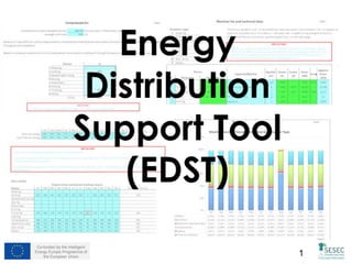
- 6. Co-funded by the Intelligent Energy Europe Programme of the European Union 6 Electrical distribution by consumer type. Monthly separation of the total electrical consumption between Production machines, Heat generators, Compressed air, Lighting, Auxiliaries and others. Fuel distribution by consumer type. Monthly separation of the total fuel consumption between Production machines, Heat generators, Auxiliaries and Others for each month. Electrical distribution by process/section (production machinery), all electricity is distributed by processes. Thermal energy distribution by process/section (production), all thermal energy is distributed by processes. Full electrical discretization including both consumer type and productive process/section. Full thermal energy discretization including both consumer type and productive process/section. Data to be used in EMBT. Note: Due to the fact that in this energy distribution tool calculates based on machine data and estimations, it can be replaced by direct measurements using portable or fixed energy meters, providing that the inputs necessary for EMBT are observed. Preview: Results to expect Introduction – Manual
- 7. Co-funded by the Intelligent Energy Europe Programme of the European Union 7
- 8. Co-funded by the Intelligent Energy Europe Programme of the European Union 8Introduction – Manual
- 9. Co-funded by the Intelligent Energy Europe Programme of the European Union 9 Steps 1. Set the Scope 2. Setup the Excel 3. Input Technical Data 4. Check Distribution Output, Thermal and Electrical Energy 5. Data for EMBT (data to be exported and used in EMBT) Introduction – Manual
- 10. Co-funded by the Intelligent Energy Europe Programme of the European Union 10 1. Set the scope What do you expect to get from the ESS-EDST-tool? E.g.: Energy distribution within the plant per segment and/or process Who in your company will work with the ESS-EDST-tool? You will need the company machine list with technical data, this list should also include lighting technical data. If company wishes to be thorough and include all consumers don’t forget the office equipment and non productive (e.g. food conservation and confection, etc.) Work hours per process and machine workload What will be the next steps? E. g. Attribute energy cost within the plant per segment and/or process Introduction – Manual
- 11. Co-funded by the Intelligent Energy Europe Programme of the European Union 11 2. Setup the Excel MS-Excel 2010 or later required The most current version is available on www.sesec- training.eu Macros have to be enabled The ESS-EDST was developed using macros. You need to enable macros in order to be able to fully use the ESS-EDST Introduction – Manual
- 12. Co-funded by the Intelligent Energy Europe Programme of the European Union 12 2. Activate Macros Introduction – Manual
- 13. Co-funded by the Intelligent Energy Europe Programme of the European Union 13 3. Sheet: Introduction All sheets are navigable but tool use should follow a left to right order Read the full intro, it will help to understand tool inner works Introduction – Manual
- 14. Co-funded by the Intelligent Energy Europe Programme of the European Union 14 Sheet: Introduction Introduction – Manual In this module we will use an example of a theoretical company named XPTO. This company produces two segments: Socks that are included in segment “Underwear and Bras” and Seamless T-Shirts that are included in segment “T-shirts and related - knitted”. The main output from the company are socks that represent nearly 100% of the production , T-shirts represent a very small percentage of production being considered almost as sample production. The EDST is a tool that’s only able to analyse one segment at a time, this implies that one EDST excel file must be filled per each segment produced by a company. In this example, the XPTO company produces two segments, the “Underwear and Bras” segment and the “T-shirts and related - knitted” segments, this means that two EDST files must be created, one per segment. Note: The EDST tools with the examples (one per segment) are also available in SESEC’s website.
- 15. Co-funded by the Intelligent Energy Europe Programme of the European Union 15 The first sheet is the “Start up & Company Data” sheet. In this sheet you’ll be asked to identify the company, the user and the year that is currently being analyzed. You will also be asked, in case the company has more than one segment, to perform a first attempt to distribute electrical and thermal energy trough the various segments based on company's experience. Finally you will be asked to input the amount of hours worked in each process per month on each specific segment. Sheet: Start up & Company Data (1) Introduction – Manual Fill company data. All data to be inserted is to be related to the indicated year
- 16. Co-funded by the Intelligent Energy Europe Programme of the European Union 16 In these tables you must input an estimation of the monthly energy that is used in each segment, the idea behind this is use the company’s experience to make a first division of energy consumption by segment. As the user becomes familiar with the SESEC tools, with energy management concepts and its implementation, this energy allocation will be tuned and consequently closer to reality. Consider our example of the XPTO company, this company produces two segments “Underwear and Bras“ and “T-shirts and related - knitted” where the T-shirts segment is regarded as sample production (read slide 14). The following images show the preliminary distribution in the example. Sheet: Start up & Company Data (2) Introduction – Manual Table for “Underwear and Bras“ segment EDST file Table for “T-shirts and related - knitted” segment EDST file As you can see the bulk of energy consumption is allocated to the “Underwear and Bras“ segment due to the fact that almost all production is related to this segment, also note that in each month both the electrical and thermal energy adds to 100% (e.g. January electrical consumption is 98% for “Underwear and Bras“ and 2% for “T-shirts and related – knitted”) also in August there was no T- shirts production so, inevitably, it appears as 0%. The “Control” cell is there to warn if values are lower than 0% or higher than 100%.
- 17. Co-funded by the Intelligent Energy Europe Programme of the European Union 17 The final input in this sheet concerns the hours worked in each process of each segment. When filling these tables don’t be concerned by particular machines, the objective is to input the monthly work hours of the process even if only one machine is working. The fine tune for hourly attribution is foreseen in subsequent sheets. In the example presented by the images on the left, the monthly work hours are the same for each segment because in each segment the work areas are mixed, meaning that the area where T-shirts are knitted is the same where Socks are knitted, same thing for finishing. Sheet: Start up & Company Data (3) Introduction – Manual Table for “Underwear and Bras“ segment EDST file Table for “T-shirts and related - knitted” segment EDST file
- 18. Co-funded by the Intelligent Energy Europe Programme of the European Union 18 Sheet: Machinery (1) Introduction – Manual In the “Machinery” sheet, user is asked to input all energy consuming machines within the company except steam/hot water generators and compressed air (consider compressors and dryers), these have specific sheets for data input. This should be considered as an equipment list so input all machines regardless of segment, so the same list can be used in multiple EDST files. ... input them here for process identification. “Designation” field will filled automatically. Use numbers 1 trough 9 from this list, and... “Observations” and electrical data are fields are optional but useful to input important information. Note: All green fields are optional and are not required by the tool for calculation.
- 19. Co-funded by the Intelligent Energy Europe Programme of the European Union 19 Sheet: Machinery (2) Introduction – Manual In the “Equipment/Machine” column (see picture below) user is asked to input each machine, or group of machines, related to the indicated process. User can either input one machine per cell or group similar machines that usually work the same hours and have the same electrical characteristics, i.e. similar consumption. As an example consider a company with 5 knitting machines; Example 1: Machines are of the same model and/or same electrical characteristics, machine 1, 2 and 3 usually work all production hours and the 4th and 5th usually work half the time. In this example user should input machines 1,2 and 3 in one row and 4 and 5 in a different row. Example 2: Machines are of the same model and/or same electrical characteristics but have totally different work hours. User should input each machine in a different row. Example 3: Machines are NOT of the same model and/or same electrical characteristics but work continuously trough all work hours. User should input each machine in a different row. Nevertheless if the electrical characteristics can be considered the same, meaning they have similar consumption, these can be grouped in one single row. Justification when grouping similar machines consider not only the electrical characteristics, i.e. similar consumption, but also if they have similar work hours.
- 20. Co-funded by the Intelligent Energy Europe Programme of the European Union 20 Sheet: Machinery (3) Introduction – Manual “Apparent Power” calculation can be made by using the support tool available in the same sheet. Retrieve electrical data from each machine and follow the tool indication for kVA calculus
- 21. Co-funded by the Intelligent Energy Europe Programme of the European Union 21Introduction – Manual Sheet: Machinery Electrical Energy (1) In the “Machinery Electrical Energy” sheet, user is asked to input, in a monthly basis, the specific hours worked and the workload of all energy consuming machines inputted in the previous sheet, the “Machinery” sheet. Calculus here will convert the “Apparent Power” to “Apparent Energy”. Concerning: Work hours This represents the total monthly work hours of a machine or group of “similar” machines. Please note that you should NOT add work hours if inputting for a group of machines, i.e. if the group includes 2 machines and 1 works 185h and the other works 200h do not input 385h, input an average or a value between 185 and 200; Workload Work load is an estimate percentage of the effective work done by the machine within it's work hours, i.e. consider a value between 0% if machine is stopped and 100% if machine is at full power/load. Note that all other fields were automatically filled based on data already inserted in the “Machinery” sheet.
- 22. Co-funded by the Intelligent Energy Europe Programme of the European Union 22Introduction – Manual Sheet: Machinery Electrical Energy (2) Table for “T-shirts and related - knitted” segment EDST file Table for “Underwear and Bras“ segment EDST file These two images depict the January month of both EDST files concerning the two produced segments of the example, the “Underwear and Bras“ and “T-shirts and related - knitted”. The most important thing to note is that the values for “T-shirts and related - knitted” machines in the “Underwear and Bras“ table are marked as 0 and vice-versa in the “T- shirts and related - knitted” table.
- 23. Co-funded by the Intelligent Energy Europe Programme of the European Union 23Introduction – Manual In the “Lighting” sheet, user is asked to input all lighting within the company. Much like the “Machinery” this should be considered as an equipment list so input all lighting regardless of segment, so the same list can be used in multiple EDST files. Sheet: Lighting (1) ... input them here for process identification. “Area designation” field will be automatically filled. Use numbers 1 trough 8 from this list, and...
- 24. Co-funded by the Intelligent Energy Europe Programme of the European Union 24Introduction – Manual Sheet: Lighting (2) ... input them here for equipment identification. “Type” field will be automatically filled . Use numbers 1 trough 58 from this list, and... The next step is to input the type of lighting used in the various areas, the list in the right has 58 combinations of lighting that is commonly used, cycle trough the list and match each area with its installed lighting types. In the image below note that for both “Knitting” and “Finishing” the “Observations” field indicates “Socks & T-Shirts”, this means that both segments are knitted and finished in the same areas. Because of this, in both EDST files the “Lighting” sheet has the same data for production areas.
- 25. Co-funded by the Intelligent Energy Europe Programme of the European Union 25Introduction – Manual Sheet: Lighting (2) Finally, in the same table, user is asked to input the quantity of selected lighting types and their utilization coefficient. With all data inputted in this sheet the tool calculates the “Apparent Power” and in the background, using the work hours inputted earlier, calculates to “Apparent Energy”. Concerning: Quantity Always assume “Quantity” as quantity of lamps even if in the company there are double or triple light fixtures, i.e. there are 10 double light fixtures, when inputting quantity input 20 lamps. Include all working lamps even if usually they’re turned off. Utilization coefficient Although all were accounted for, not all lamps are turned on during work time, use "Utilization coefficient" to tune the amount of time lamps are turned on. In the example (see image below) in the “knitting” area there are 150 fluorescent tube 36W lamps with electronic ballast that are, in average, turned on 70% of the time.
- 26. Co-funded by the Intelligent Energy Europe Programme of the European Union 26 In the “Compressed air” sheet, user is asked to input the “Apparent power” the “Average work load” and an theoretical airflow distribution. Concerning: • Apparent power this calculation can be made by using the support tool available in the “Machinery” sheet (slide 20). Retrieve electrical data from each active compressor and dryer and follow the tool indication for kVA calculus. • Average work load the average work load can be seen as the ratio between the compression time and the total working time. Although the best way is to proceed with electrical measurements, a practical method can be applied by only using a watch, imagine a compressor that in an 60 min time frame effectively compresses during 30 min, the average work load is 30/60=50% (if you have enough patience increase the time frame for better results). The previous method applies to on/off compressor type, if compressor has variable speed then the data to retrieve the average work load should be available in the compressor controller. • Theoretical airflow distribution Because it's very difficult, without measurements, to distribute compressed air consumption the best approach is to estimate consumptions throughout the installation based on company's experience. The best way to estimate is to identify, in all processes, where are the biggest compressed air consumers their quantity and average work hours, and correlate the three, then fine tune the results with the same data but from the less intensive compressed air consumers. Introduction – Manual Sheet: Compressed Air (1)
- 27. Co-funded by the Intelligent Energy Europe Programme of the European Union 27Introduction – Manual In the examples both segments have the same theoretical distribution for two main reasons: • The main concern while analyzing distribution was the “Underwear and Bras” segment because this is the main segment in the company; • The weight for compressed air consumption machines concerning Knitting and Finishing is practically the same in both segments, i.e., ratio for Knitting and Finishing is about 60%-40% regardless of product. Sheet: Compressed Air (2)
- 28. Co-funded by the Intelligent Energy Europe Programme of the European Union 28 The “Steam / Hot water” sheet has a similar approach as the “Compressed air” sheet. Here user is asked to input the “Apparent power” the “Average work load”, an theoretical steam/hot water flow distribution, and the main difference between this and the compressed air sheet is the introduction of an reduction coefficient. Also the sheet predicts both fuel and electrical steam/hot water generators Concerning: • Apparent power this calculation can be made by using the support tool available in the “Machinery” sheet (slide 20). Retrieve electrical data from each active steam/hot water generator and follow the tool indication for kVA calculus. Remember that this is electrical consumption related and has nothing to do with thermal power. • Average work load the average work load can be seen as the ratio between the effective burn/resistance activation time and the total working time. Although the best way is to proceed with electrical measurements, a practical method similar to one in the the compressed air, can be applied by only using a watch, imagine a steam/hot water generator that in an 60 min time frame effectively burns/activates resistance during 30 min, the average work load is 30/60=50% (if you have enough patience increase the time frame for better results). Introduction – Manual Sheet: Steam / Hot water (1)
- 29. Co-funded by the Intelligent Energy Europe Programme of the European Union 29 • Reduction coefficient Reduction coefficient works basically the same way has the “Utilization coefficient” in the “Lighting” sheet (slide 25), the work hours were already identified in "Company data" page but not all generators are turned on during that time, use "Reduction coefficient" to tune the amount of time generators are turned on; Introduction – Manual Sheet: Steam / Hot water (2) Note that steam/hot water generators, both electrical and combustible generators, are available for data input. You can input data in one or both types and if you have more than one equipment in one of type input “Apparent power” sum and fine tune with “Average work load” and “Reduction coefficient”.
- 30. Co-funded by the Intelligent Energy Europe Programme of the European Union 30 • Theoretical steam/hot water flow distribution Because it's very difficult, without measurements, to distribute steam/hot water consumption the best approach is to estimate consumptions throughout the installation based on company's experience. The best way to estimate is to identify, in all processes, where are the biggest steam/hot water consumers their quantity and average work hours, and correlate the three, then fine tune the results with the same data but from the less intensive steam/hot water consumers.The main difference between this and “Compressed air” sheet is a monthly distribution because heat consumption is more affected by season, e.g. comfort heating. Introduction – Manual Sheet: Steam / Hot water (3)
- 31. Co-funded by the Intelligent Energy Europe Programme of the European Union 31 The “Fuel” sheet was created to differentiate the fuel consumption that is used to produce steam/hot water via heat generators (indirect heat production) and the combustible that is used directly in a production machine like a dryer, so a division of the total consumed fuel directly and indirectly is imperative. Concerning distribution, a recurrent problem persists, without measurements is very difficult to distribute fuel consumption so the same approach is to be taken as in "Compressed air" and "Steam/Hot water" consumption. In the table input the theoretical distribution all combustible consumption regardless of were it is burned (directly or indirectly). Introduction – Manual Sheet: Fuel (1) Based on existing meters or on your perception and experience, input here the % of fuel that is used directly, i.e., the fuel that is burned directly in production machines like dryers and heaters.
- 32. Co-funded by the Intelligent Energy Europe Programme of the European Union 32 While the previous table, in “Steam/hot water” sheet, only asks for steam/hot water distribution, i.e., hot fluid distribution, this one wants to know how the consumption of combustible is distributed. As an example imagine a company that has processes A and B, in process A only steam is consumed while in process B both steam and combustible are consumed. Steam distribution is 80% in process A and 20 % in process B, this is the result for “Steam/hot water” sheet. In this sheet, “Fuel” sheet, the combustible distribution is 50% for both processes, this happened because there are very intensive machines that burn combustible directly that shifted the thermal weight distribution between processes. Introduction – Manual Sheet: Fuel (2) In our example sheet (see image) the company does not consume combustibles directly but when distributing the entire combustible consumption all of it is used for finishing (indirectly trough steam) Note that also here, similarly to the “Steam/hot water” sheet, there is a monthly distribution also because heat consumption is more affected by season, e.g. comfort heating.
- 33. Co-funded by the Intelligent Energy Europe Programme of the European Union 33 Results in “Results” sheet are presented both numerically and graphically, the data is divided in 6 pages with specific results: • Page 1 In this page you can find the Electrical distribution by consumer type, it separates the total electrical consumption between Production machines, Heat generators, Compressed air, Lighting, Auxiliaries and others. • Page 2 In this page you can find the Fuel distribution by consumer type, it separates the total fuel consumption between Production machines, Heat generators, Auxiliaries and Others. • Page 3 In this page you can find the monthly Electrical distribution by process/section (production machinery). Here, all electricity is distributed by processes, so each process includes its relative electricity portion of compressed air, lighting, etc. • Page 4 In this page you can find the monthly Thermal energy distribution by process/section (production), thermal energy represents the burnt fuel and heat provided by an external source. All thermal energy is distributed by processes, so each process includes its relative thermal energy produced in the heat generators and/or from provided by an outside source. • Page 5 In this page you can find full Electrical energy discretization including both consumer type and productive process/section. • Page 6 In this page you can find full Thermal energy discretization including both consumer type and productive process/section. Note that this is where combustibles are burnt - same principles as in page 2. Introduction – Manual Sheet: Results (1)
- 34. Co-funded by the Intelligent Energy Europe Programme of the European Union 34Introduction – Manual Sheet: Results (2) Some results from “Underwear and Bras” segment EDST sheet (example file)
- 35. Co-funded by the Intelligent Energy Europe Programme of the European Union 35Introduction – Manual Sheet: Results (3) Some results from “T-shirts and related – knitted” segment EDST sheet (example file)
- 36. Co-funded by the Intelligent Energy Europe Programme of the European Union 36Introduction – Manual Sheet: Data for EMBT (1) Results in this sheet are to be used in EDST's sister tool, the EMBT (Energy Management and Benchmarking Tool) more particularly in the "Energy input“ and “Benchmark” sheets. As you may remember, this tool only provides the energy distribution of one production segment, meaning that for multiple production segments multiple EDST's must be built. The same principle applies to benchmarking, the data in one EDST is only valid for that specific analyzed. This sheet has three different results provided by three tables, values are available after clicking the button: • Table 1, Energy Distribution in Segment This table represents the energy distribution in this segment. Just select and copy all the values in this table and paste them in table "Input Energy Distribution by Process" of the "Energy input" sheet; • Tables 2 & 3, Benchmarking for Segment These tables present the necessary data by providing the energy ratio, both electrical and thermal, on benchmarkable processes in the selected segment. Just select and copy all the values in both tables and paste them in tables "Electrical energy consumption" and "Fuel energy consumption" of the "Benchmarking“ sheet. Click here to retrieve values. These values are based on the data from “Results” sheet.
- 37. Co-funded by the Intelligent Energy Europe Programme of the European Union 37Introduction – Manual Sheet: Data for EMBT (2) Data to be inserted in EMBT from “Underwear and Bras” segment EDST sheet (example file)
- 38. Co-funded by the Intelligent Energy Europe Programme of the European Union 38Introduction – Manual Sheet: Data for EMBT (3) Data to be inserted in EMBT from “T-shirts and related – knitted” segment EDST sheet (example file)
- 39. Co-funded by the Intelligent Energy Europe Programme of the European Union 39 Readings [1] CITEVE (2013): Critical Energy Saving Points for the Clothing Manufacturing Process/Factory Environment, Deliverable D3.1 [2] CITEVE (2013): O3.2 “Energy Saving Scheme (ESS) Guide for Companies” and O3.5 “Guidance Document” [3] GHERZI (2013): Energy Data, Deliverable D2.2 [4] DITF (2014): Euratex Overall SESEC Approach, presentation available on www.sesec-training.eu [5] CITEVE (2014): EMBT (Energy Management and Benchmarking Tool), presentation available on www.sesec-training.eu [6] ENEA (2014): SAT (Self Assessment Tool), presentation available on www.sesec-training.eu Introduction – Manual
- 40. Co-funded by the Intelligent Energy Europe Programme of the European Union 40 Pictures Slide 8 – Dennis Skley: *grübel* – URI: http://www.flickr.com/photos/dskley/8627475625/sizes/z/in/photostream/ License: CC BY-ND 2.0 (http://creativecommons.org/licenses/by-nd/2.0/legalcode) Slide 9 – Carissa Rogers: kid to do list, list, Be happy and go home – URI: http://www.flickr.com/photos/rog2bark/3437630552/sizes/m/in/photolist-6eLKNh-c1mn5W-9Lcbki-9jeZKu-CdE9B- 6tQG1N-8cuPQg-6oCMfR-5R2t5b-9uCMNF-7WWKna-82Z8Cz-87uSWj-839wC-8QW9Yq-7pHc1U-6qsYHC-gu1Ra- 7Jq5QH-7Mfehz-7VWPxJ-6J37Hp-4QCVn9-8QzzeL-8w3ARY-5JaQRk-5wvNsm-fMnd2-ffgRgs-4yar1X-dr9xUw-dJLTso- 3bLKoc-5sane8-eT8xC-5QjTMr-55xTxK-iYZum-i8xKL-61m8xK-6YzqVs-7JKQkd-5SyRgw-4VSKqq-avZUVo-4ZwxHC-3svSV- 4qU25r-4sCr3S-PVLFS-5rMwqS/ License: CC BY 2.0 (http://creativecommons.org/licenses/by/2.0/legalcode) All other pictures (except the logos) are screenshots of the EDST-Tool by SESEC CC BY-SA 2.0 (http://creativecommons.org/licenses/by-sa/2.0/legalcode), Introduction – Manual