A Review Of Hole Geometry And Coolant Density Effect On Film Cooling
•
0 likes•13 views

Academic Paper Writing Service http://StudyHub.vip/A-Review-Of-Hole-Geometry-And-Coolant-D 👈

Recommended
More Related Content
Similar to A Review Of Hole Geometry And Coolant Density Effect On Film Cooling
Similar to A Review Of Hole Geometry And Coolant Density Effect On Film Cooling (20)
More from Brittany Allen
More from Brittany Allen (20)
Recently uploaded
Recently uploaded (20)
A Review Of Hole Geometry And Coolant Density Effect On Film Cooling
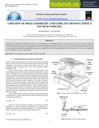
- 1. Frontiers in Heat and Mass Transfer (FHMT), 6, 8 (2015) DOI: 10.5098/hmt.6.8 Global Digital Central ISSN: 2151-8629 1 A REVIEW OF HOLE GEOMETRY AND COOLANT DENSITY EFFECT ON FILM COOLING Srinath Ekkada,* Je-Chin Hanb a Dept. of Mechanical Engineering, Virginia Tech, Blacksburg, VA 24061, USA b Dept. of Mechanical Engineering, Texas A&M University, College Station, TX 77843, USA ABSTRACT Improved film cooling hole geometries and effect of coolant density on film cooling have been a focus since the 1970s. One of the first studies on modifying hole exit to improve film cooling effectiveness and quantifying coolant density effect was from Prof. Goldstein’s group. This paper provides an overview of the development and implementation of hole exit geometries as well as coolant density study over the past few decades and the impact on future studies of advanced hole geometries under realistic engine-like coolant-to-mainstream density ratio conditions. This work is not intended to be a comprehensive review of the literature. Keywords: Film cooling, Hole geometry effect, Density ratio effect. 1. FUNDAMENTALS OF FILM COOLING “Film Cooling is the introduction of a secondary fluid (coolant or injected fluid) at one or more discrete locations along a surface exposed to a high temperature environment to protect that surface not only in the immediate region of injection but also in the downstream region” (Goldstein, 1971). Turbine airfoil surfaces, shrouds, blade tips and endwalls are all cooled using discrete hole film cooling. A typical cooled airfoil is shown in Fig. 1. The figure shows the various locations where coolant is injected into the mainstream from inside the airfoil through discrete holes. Film cooling protects the airfoil surface directly compared to internal cooling techniques that remove heat from the inside surface. Film cooling also removes heat from blade surface through the film hole by internal convection. The thermal protection is expected to provide reduced heat load to the airfoil surface. Designers need to know the net heat load into the component surface when film is injected. Due to complex nature of discrete hole injection, there is a need to know the local wall temperature (Tw) under the film and the gas side heat transfer coefficient with film injection. Both these components are required to estimate reduced heat load to the surface. Figure 2 shows the film injection geometry and heat transfer model associated with it. Typically, the heat load to surface without film cooling is represented as heat flux. ( ) w g T T h q − = ′ ′ 0 0 (1) where h0 is the heat transfer coefficient on the surface with wall temperature Tw and oncoming gas temperature (Tg). When film is injected on the surface, the driving temperature is Tf, film temperature, which is a mixture of gas (Tg) and coolant temperature (Tc). ( ) w f T T h q − = ′ ′ (2) ___________________________________ * Corresponding authors. Email: sekkad@vt.ed Fig. 1 Typical cooled airfoil (Hyams et al., 1996). Fig. 2 Schematic of film cooling concept. Frontiers in Heat and Mass Transfer Available at www.ThermalFluidsCentral.org
- 2. Frontiers in Heat and Mass Transfer (FHMT), 6, 8 (2015) DOI: 10.5098/hmt.6.8 Global Digital Central ISSN: 2151-8629 2 (a) (b) Fig. 3 Computed temperature distributions of injection through angled holes (Leylek and Zerkle, 1994). where h is the heat transfer coefficient on the surface with film injection. Also, a new term film effectiveness (η) is introduced, where η = (Tg - Tf)/(Tg - Tc). To obtain any benefit from film cooling, the heat load ratio, q"/ q0", should be below 1.0. − − − = − − = w g c g w g w f T T T T h h T T T T h h q q η 1 0 0 " 0 " (3) Film cooled airfoils have leading edge film cooling holes called showerhead and downstream pressure and suction surface film cooling. The showerhead cooling has several film hole rows near the stagnation point on the blade leading edge. Pressure and suction surface cooling is achieved by single or multiple rows of injection holes at several locations. Fig. 1 is a schematic to show some of the important parameters affecting airfoil film cooling. The oncoming mainstream flow, blade wakes, rotation, secondary flow effects on endwalls, and tip flows are important external effects. The film hole geometry and configuration and coolant mass flow through the holes also affect film-cooling performance. In general, heat transfer coefficients increase with coolant injection through cooling holes, however, the surface protection by film coolant should be greater than the penalty by the enhanced heat transfer coefficients. Therefore, the heat load ratio, Eq. (3), must be less than one for good film cooling designs. Figure 3 shows computed temperature distributions downstream of injection through an angled hole (Leylek and Zerkle, 1994). The temperature distributions clearly show the counter-rotating vortex structure and kidney-shaped cross-section of the coolant jet. Two coolant-to-mainstream blowing rates of 0.5 and 2.0 are shown. At low blowing rate of 0.5, the jet velocity is lower than the mainstream flow. (a) (b) (c) Fig. 4 Geometry of injection section: (a) shaped injection channels, (b) long cylindrical injection channels, (c) cylindrical injection channels through a thin wall (Eckert et al., 1970). Fig. 5 Comparing diffuser hole performance with cylindrical hole (Eckert et al., 1970). The stronger mainstream forces the jet down toward the surface. However for a blowing rate of 2.0, the jet-mainstream interaction region is larger. The jet appears to lift-off farther from the surface. Also, more mainstream flow appears to entrain underneath the jet. Studies in redefining hole geometries have focused on this high lift-off effect for cylindrical hole exits at higher blowing ratios. Modifying the jet penetration into the mainstream has been the focus in improving the jet cooling effectiveness. For better performance, cooling holes with compound angles, diffuser shaped expansions, and holes in slots are used. Increase in lateral momentum in compound angle holes, decrease in axial velocity in the shaped holes and reduced jet momentum and 2-D jet coverage in slots lead to an increase in cooling efficiency. This jet spreading provides a better lateral coverage thus a higher laterally averaged cooling efficiency is obtained. There have been many film cooling studies in open literature, for example, Kercher (1998), documented more than a thousand paper’s titles, Han et al. (2012) reviewed several hundreds of papers in their book’s chapter 3. The present review paper focuses only on advanced film-hole geometry and coolant density effect on film cooling.
- 3. Frontiers in Heat and Mass Transfer (FHMT), 6, 8 (2015) DOI: 10.5098/hmt.6.8 Global Digital Central ISSN: 2151-8629 3 Fig. 6 Illustration of the geometry of trapezoidal holes as studied by Makki and Jakubowski (1986). Fig. 7 Illustration of the hole configurations studied by Sen et al. (1996) and Schmidt et al. (1996). 2. FILM COOLING HOLE GEOMETRY DEVELOPMENT 2.1 Early Work (1970s) Eckert et al. (1970) studied injection through circular tube shooting into a cross mainstream. They indicated that for the same flow of secondary fluid, considerably less cooling or protection is obtained with discrete holes than with injection through a continuous slot. This less efficient performance is apparently due to the penetration of the jets from the individual holes into the free stream, permitting the hot free stream gases to flow under the secondary fluid close to the surface to be protected. They suggested that the trajectory of a three-dimensional jet entering a cross-stream is primarily determined by the momentum flux (or dynamic head) ratio of the two fluids, namely (ρU2 )c/(ρU2 )∞. This may be contrasted to two-dimensional film cooling in which the data can often be correlated using the blowing parameter (mass flux ratio), (ρU)c/(ρU)∞. The last mentioned parameter is indicative of the enthalpy deficit of the entering secondary fluid and would be expected to play a role in predicting film cooling effectiveness. However, when flow conditions are such that the jet can separate from the surface, the momentum flux ratio cited above can also be of importance. Goldstein et al. (1974) indicated that the passageway for the secondary fluid might be designed to produce a Coanda effect at the exit so that injected fluid would follow the surface rather than penetrate into the free stream. They studied three geometries, one with a “shaped” exit, the other with a long tube supplying the hole exit to compare with the baseline short cylindrical hole. Fig. 4 shows the three geometries studied. Their experiments indicated the improvement of three-dimensional film cooling which can be obtained with shaped channels for the secondary flow. The use of a passage with an initially round cross section widened to each side by an angle of about 10 degrees significant1y increased the film cooling effectiveness immediately downstream of either a single hole or a hole in a row of holes. In addition, the shaped hole appreciably increased the spreading of the secondary flow so that the film cooling effectiveness at positions laterally displaced from the centerline of a hole is also much greater than that found downstream of a cylindrical hole. One explanation of the increased effectiveness with shaped holes is that the mean velocity of the secondary flow is decreased with the larger exit area. This lower effective blowing rate causes the jet to stay closer to the wall rather than penetrating into the mainstream and accounts for the higher-film cooling effectiveness, particularly at high blowing rates. Figure 5 summarizes the essential effect of exit hole shaping on centerline film effectiveness at two distances downstream of the holes (Eckert et al., 1970). The significant decline in film cooling effectiveness with increased blowing through cylindrical secondary flow channels has been attributed to the penetration of the secondary fluid jets into the mainstream away from the adiabatic surface. Up to the blowing rate that produces separation from the wall (0.4-0.6), the two geometries give very similar results. For high blowing rates, the shaped hole geometry shows increasing effectiveness and flattens out. 2.2 Early Work (1980s) Haller and Camus (1984) performed aerodynamic loss measurements on a two-dimensional transonic cascade with holes that had a spanwise flare angle of 25 deg and found significant improvements in film-cooling effectiveness without any additional loss penalty. Papell (1984) experimentally studied a novel cusp shape hole exit fand found that shaping the hole with a cusp (similar in appearance to a kidney bean) induced strong longitudinal vortex structures within the film hole. With the aid of flow visualizations, he summarized that creating these vortical structures enabled the crossflow to use its energy to force the jet down to the surface, rather than itself creating the counter-rotating vortices. Further, he placed the cusp on the leeward side (TE) to force the film hole secondary flow to rotate in a direction opposite of that traditionally observed in cylindrical film holes. Makki and Jakubowski (1986) studied trapezoidal exit holes and found that forward-and-laterally positioned film holes provided lower heat transfer coefficients and higher film cooling effectiveness when compared to round holes leading overall heat flux reduction to the test surface as shown in Fig. 6. Their conclusion was based on comparison of the cooling performance for forward-and- laterally expended holes with circular film hole geometries using a 35° inclination angle and a pitch to diameter ratio of 3. Note that more studies exist and only a handful could be provided as pertinent examples. 2.3 Work in 1990s Sen et al. (1996) and Schmidt et al. (1996) studied the effect of compound-angle film-cooling on heat-transfer coefficients and film effectiveness. They studied three different hole geometries and measured heat-transfer coefficient enhancement and film effectiveness over a surface without film cooling. Compound-angle holes are holes that are inclined along the mainstream direction with an additional angle of inclination in the lateral or span-wise direction. Fig. 7
- 4. Frontiers in Heat and Mass Transfer (FHMT), 6, 8 (2015) DOI: 10.5098/hmt.6.8 Global Digital Central ISSN: 2151-8629 4 (a) (b) Fig. 8 Variation of spatially averaged: (a) heat transfer coefficient ratios, (b) film cooling effectiveness for configurations studied by Sen et al. (1996) and Schmidt et al. (1996). illustrates the three-hole geometries studied by Sen et al. (1996). The first case was a round of holes and called the simple-angle hole, where the holes are inclined only along the mainstream, with no lateral angle. The second case was a compound angle hole that had an additional angle of 60° away from the mainstream in the lateral direction. The third case was the shaped hole with the 15° forward expansion and the 60° compound angle. As shown in the figure, these holes had the diffusing exit inclined further along the hole exit, at 15°. Figure 8(a) presents the variation of spatially averaged heat-transfer coefficient with increasing momentum flux ratio (I). The heat-transfer coefficient ratio increases with increasing I for the round hole (CA = 0) and the round hole (CA = 60). The heat-transfer coefficient ratio is very high for the forward expansion hole. This may be due to increased lateral (a) (b) (c) Fig. 9 Hole configuration studied by Gritsch et al. (1998b). mixing of jets with the mainstream. However, the ratio decreases with increased forward-expansion hole at large I. The ratio values for the round hole, CA = 60, continually increase with increasing I. Fig. 8(b) compared the spatially averaged film effectiveness for the three geometries against the momentum flux ratio (I). The results are shown at two hole-to-hole, pitch-to-diameter (P/D) ratios of 3.0 and 6.0. Again, it is evident that hole geometry does not provide significant effect at low momentum flux ratio (or blowing ratio). But with compound-angle hole injection (CA = 60°), the film effectiveness is significantly improved at higher momentum flux ratios. With forward expanded exits and CA = 60°, film effectiveness improves further at higher I values. The effect is reduced for the larger P/D ratio of 6.0. Overall effectiveness values are also lower for each case with an increased P/D ratio. Thole et al. (1998) showed that jet penetration as well as local velocity gradient in the coolant-mainstream mixing region was significantly reduced for holes with expanded exits as compared to a cylindrical hole at the same blowing rate. Gritsch et al. (1998b) investigated the same hole geometries as that of Thole et al. (1998) that included a cylindrical hole and compared with a fan-shaped diffuser hole and a laid-back fan shaped diffuser hole. Fig. 9 presents the three geometries studied by Thole et al. (1998) and Gritsch et al. (1998b). The diameter of the cylindrical hole and the diameter of the cylindrical inlet section of the expanded holes was 10 mm. The blowing ratio calculation was based on this inlet area for all three holes. The length-to-diameter ratio (L/D) was 6 for all hole geometries. The lateral expansion angle of both expanded holes was 14 deg, resulting in a hole width of 30 mm at the hole exit. The forward expansion angle of the laid-back fan-shaped hole was 15 deg, resulting in a hole length of 40 mm at the hole exit. The exit-to-entry area ratio of the fan-shaped and laid-back fan-shaped hole were 3.0 and 3.1, respectively (areas perpendicular to hole axis). They indicated that, for the simple cylindrical hole, the film effectiveness decreases significantly with increasing blowing ratio. The jets penetrate the mainstream with increasing blowing ratio, resulting in lower film effectiveness. The distribution clearly shows jet separation at a higher blowing ratio. For the fan-shaped hole, the film effectiveness is not as significantly reduced with increasing blowing ratio. The jets spread better over a greater spanwise area due to the flared exit. However, at higher blowing ratio, the effect of jet separation is still evident just downstream of injection. For the laidback fan-shaped hole, the local film effectiveness downstream of the film hole is lower than that for the fan- shaped hole. However, the jet spreads more in the spanwise direction, providing higher film effectiveness laterally. Gritsch et al. (1998b) also presented the heat transfer coefficients for the same holes. They indicated that heat transfer coefficients for fan shaped holes were much lower due to increased cross-sectional area of the hole exits. The reduced momentum produces lower jet penetration and mixing thus reduced local turbulent production. Gritsch et al. (1998a) presented discharge coefficients for the holes studied in Gritsch et al. (1998a and 1998b). Laidback fan shaped and fan shaped holes produced similar discharge coefficients which were typically higher than for cylindrical holes especially for lower pressure ratios between coolant total pressure and mainstream pressure.
- 5. Frontiers in Heat and Mass Transfer (FHMT), 6, 8 (2015) DOI: 10.5098/hmt.6.8 Global Digital Central ISSN: 2151-8629 5 (a) REF (b) FDIFF (c) LDIFF (d) ISHAP (e) CUSP Fig. 10 Schematic of the five hole geometries studied by Hyams and Leylek (2000). Kohli and Thole (1997) studied the effect of coolant entrance condition for both cylindrical and diffuser shaped holes computationally. The coolant channel orientation played a major role in the effectiveness distributions on the test surface, based on their results. Hyams et al. (1996) studied the effects of slot jet shaping on the heat transfer downstream of a slot jet. It was found that shaping of the slot inlet and exit provided significant gains in the film cooling performance. 2.4 2000-2014 Hyams and Leylek (2000) computationally studied five distinct film cooling configurations in Fig. 10: (a) cylindrical film hole (reference case), (b) forward-diffused film hole, (c) laterally diffused film hole, (d) inlet shaped film hole, and (e) cusp-shaped film hole. Fig. 11 shows the five basic film hole shapes investigated in this work. The configurations were: (a) cylindrical (REF), (b) forward diffused (FDIFF), (c) laterally diffused (LDIFF), (d) inlet shaped (ISHAP), and (e) cusp shaped (CUSP). The fifth hole indicated as CUSP is the same geometry proposed by Papell (1984) in the 1980s. They found that the laterally (a) REF (b) FDIFF (c) LDIFF (d) ISHAP (e) CUSP Fig. 11 Comparison of temperature footprints from the five geometries in Figure 9 (Hyams and Leylek, 2000). diffused film hole provides the best coverage and highest effectiveness. The forward diffused film hole performs well along the centerline, but does not spread laterally. The cylindrical and inlet-shaped film holes perform poorly at both blowing ratios; the coolant lifts off from the test surface in these cases. Fig. 11 shows the computed temperature distributions for all five cases indicating the jet spreading and coverage. Sargison et al. (2001a and 2001b) presented experimental measurements of the performance of a new film cooling-hole geometry – the Converging Slot-Hole or Console as shown in Fig. 12. This novel, patented geometry has been designed to improve the heat transfer and aerodynamic loss performance of turbine vane and rotor blade cooling systems. The laterally averaged adiabatic effectiveness results demonstrated that the console cooling effectiveness approached that of the slot, as does the fan shaped-hole effectiveness. The console laterally averaged heat transfer coefficient was similar to the slot, and higher than the cylindrical and fan shaped-hole results. The slot and console does not significantly change the boundary layer flow compared with the case of no film cooling, and hence the heat transfer coefficient is similar. The aerodynamic performance of the console was also investigated, and it was shown that the aerodynamic loss due to a console is significantly less than for fan shaped or cylindrical film cooling-holes. Teng et al. (2001a and 2001b) reported the effect of unsteady wake on gill-hole film cooling with shaped holes. Results showed the film cooling effectiveness for laidback fan-shaped hole increases but heat transfer coefficients decreases as compared with the cylindrical holes. Saumweber and Schulz (2003) investigated the effect of elevated free-
- 6. Frontiers in Heat and Mass Transfer (FHMT), 6, 8 (2015) DOI: 10.5098/hmt.6.8 Global Digital Central ISSN: 2151-8629 6 (a) Side view section through blade surface (b) Plan view of Console viewed from blade surface (c) Plan section along hole centerline Fig. 12 Basic console or converging slot geometry proposed by Sargison et al. (2001a and 2001b). Fig. 13 Film cooling over a blade surface comparing axial and compound angled shaped holes by Gao et al. (2008 and 2009). stream turbulence on film cooling performance of shaped holes. For cylindrical holes, elevated free-stream turbulence intensity lowers adiabatic film-cooling effectiveness at small to moderate blowing ratios. Reductions up to 40% for local effectiveness and 25% for laterally averaged effectiveness are found when the turbulence intensity is raised from 3.6 to 11%. They found that the effect of increased turbulence level is detrimental at all blowing ratios for the shaped holes as the lateral spreading of coolant could not be improved by elevated free-stream turbulence intensity. Bunker (2005) provided a review of shaped-hole technology both in terms of cooling effectiveness as well as manufacturing. Bunker quoted, “The current understanding of shaped film parametric effects and physics is relatively sparse, however, the acceptance of shaped film technology is based largely on the foundation of round film-hole data. The benefits of shaped-hole film cooling are real and substantial, so much so that these types of film holes are used whenever possible in the practice of cooling gas turbines. No single shaping of film hole stands out as an optimal geometry, as long as the general guidelines of diffusion angles and sufficient depth/length of transition are followed. As manufacturing methods progress further, additional unconventional shapes of film holes will become viable, possibly leading to even higher performance and the ability to cool components with less air.” Bunker (2009) reviewed thirty discrete hole film cooling geometries and provided eight key factors to judge the potential performance for each film hole geometry including adiabatic effectiveness, manufacturing cost, repair, geometry sensitivity, flow sensitivity, operational tolerance, and strength/durability. Bogard and Thole (2006) provided a review of the literature including effects of free- stream turbulence, blowing ratio, coolant-to-mainstream density ratio, surface curvature, and hole shape on the performance of film cooling. Saumweber and Schulz (2008a) studied the effects of free-stream Mach number and free-stream turbulence, including turbulence intensity, integral length scale, and periodic unsteady wake flow on a row of cylindrical and shaped film holes. The results clearly show that the performance gain with fan-shaped holes as compared to cylindrical holes is clearly overestimated at low laboratory type conditions. Saumweber and Schulz (2008b) studied the effect of coolant flow direction prior to entrance into the film hole for both cylindrical and shaped holes. With a coolant supply channel orientation perpendicular to the cooling hole axis, they found that the counter rotating vortex pair inside the hole - typically found for plenum conditions at the inlet - is suppressed. Instead, they saw a single helical motion that is induced inside the cylindrical part of the hole. The resulting flow effects downstream of the ejection location were very different for cylindrical and fan-shaped holes. Saumweber and Schulz (2008c) studied the effect of the expansion angle of the diffuser, the inclination angle of the hole, and the length of the cylindrical part at the hole entrance on cooling performance of diffuser holes. They indicated that a combination of parameters affect overall cooling performance and different situations requires different hole geometries. Gao et al. (2008) and Gao and Han (2009) compared the effects of axial shaped hole and compound angled shaped hole on suction side and pressure side film cooling distributions by using pressure sensitive paint technique. The compound angled shaped hole provides higher film effectiveness than the axial angled shaped hole as shown in Fig. 13. The film traces were converged toward the suction side mid-span region, with no film effectiveness found near 25% of hub and 25% of tip, respectively. Note that the rotation effect is not considered in these papers. Gao and Han (2009) reported the influence of hole shape and angle on showerhead film cooling effectiveness by using pressure sensitive paint technique. Results showed the radial angle shaped hole. Lu et al. (2005) investigated the film cooling performance for a row of cylindrical holes by embedding the row in transverse slots. Transverse slots could be formed around the holes in the event that the blade surface is sprayed with TBC leaving the holes embedded in trenches. These trenches could be 2-D slots or 3-D craters depending on the type of masking used during the TBC spray process. The geometry of the transverse slot greatly affected the cooling performance downstream of injection. They investigated the effect of the slot exit area and edge shape. They indicated that embedding the holes in a slot reduced the jet momentum at exit and also spread the jets and provided two-dimensional slot jet coverage compared to the three-dimensional nature of individual jets. The wider spread of jets provided a better over film effectiveness with slight increases in heat transfer coefficients. Waye and Bogard (2006) investigated adiabatic film cooling effectiveness of axial holes embedded within a transverse trench on the suction side of a turbine vane. The narrow trench configuration provided the best adiabatic effectiveness performance with increasing adiabatic effectiveness levels with increasing blowing due to the trench suppressed coolant jet
- 7. Frontiers in Heat and Mass Transfer (FHMT), 6, 8 (2015) DOI: 10.5098/hmt.6.8 Global Digital Central ISSN: 2151-8629 7 (a) (b) (c) (d) (e) (f) (g) Fig. 14 Trench geometries studied by Lu et al. (2007a). Fig. 15 Overall heat flux ratio comparisons for different trench geometries (Lu et al., 2007a). separation. Lu et al. (2007a) presented an experimental investigation of film cooling from cylindrical holes embedded in transverse trenches where different trench depths were studied with two different trench widths. Fig. 14 shows the various trench geometries studied. They presented overall heat flux ratio comparisons for different trenches and compared the performance of the trenched holes with a shaped hole configuration. Fig. 15 shows the heat flux ratio comparison. Baseline and cases 1-6 are as shown in Fig. 14. An optimum trench depth at 0.75 D was identified as shallow and deep trenches showed worse performance. This was confirmed by the flow distributions obtained from CFD predictions. Shaped diffuser hole reduced the jet momentum at hole exit and outperformed the trench cases. Lu et al. (2007b) also presented results for cylindrical holes embedded in craters. Different crater geometries were considered for a typical crater depth which was identified by Lu et al. (2007a) as 0.75D. Fig. 16 shows the different crater geometries investigated in this study. The location of the hole inside the crater will have significant effect on the downstream cooling behavior of these holes. Hassison et al. (2007) studied film cooling adiabatic effectiveness on the suction side of a simulated vane for various configurations of coolant holes embedded in shallow transverse trenches or circular and elliptical shaped depressions. A shaped hole configuration was also tested. They compared the best trench configurations with a typical shaped hole configuration and showed similar film effectiveness performance over the range of blowing ratios. Hassison et al. (2007) (a) (b) (c) (d) (e) Fig. 16 Crater geometries studied by Lu et al. (2007b). Fig. 17 Double Jet Concept presented by Kusterer et al. (2006). presented both film cooling adiabatic effectiveness and heat transfer coefficients for cylindrical holes embedded in a 1d transverse trench on the suction side of a simulated turbine vane to determine the net heat flux reduction. Rallabandi et al. (2011) reported effect of upstream and downstream step on flat plate film cooling effectiveness on four separate hole geometries: simple angled (axial angle 30-deg) and compound angled (axial angle 30-deg, compound angle 45-deg) with cylindrical and fan-shaped film cooling holes. Results indicated an increase in film- cooling effectiveness in the region near the hole due to the upstream step for all the cases considered. This increase due to the step was found to be most significant in the case of compound angled cylindrical holes and least significant in the case of simple angled fan-shaped holes. Kusterer et al. (2006) introduced the Double-jet Film-cooling (DJFC) as an alternative film-cooling technology to conventional film- cooling design. They showed improvement of the film-cooling effectiveness by application of the DJFC. They also showed basic applicability of the DJFC to a realistic blade cooling configuration and presented first test results under machine operating conditions. From their results, the DJFC has been able to replace a row of shaped holes on the suction side of the blade without negative effects on the suction side thermal load level. Fig. 17 shows the concepts presented by Kusterer et al. (2006).
- 8. Frontiers in Heat and Mass Transfer (FHMT), 6, 8 (2015) DOI: 10.5098/hmt.6.8 Global Digital Central ISSN: 2151-8629 8 Heidmann and Ekkad (2008) introduced a novel turbine film cooling hole shape that was conceived and designed at NASA Glenn Research Center. The primary focus of this paper is to study the film cooling performance for a row of cylindrical holes each supplemented with two symmetrical anti vortex holes which branch out from the main Fig. 18 Design of anti-vortex holes and different configurations by Dhungel et al. (2009). holes. This “anti-vortex” design is unique in that it requires only easily machinable round holes, unlike shaped film cooling holes and other advanced concepts. The hole design is intended to counteract the detrimental vorticity associated with standard circular cross-section film cooling holes. This vorticity typically entrains hot free-stream gas and is associated with jet separation from the turbine blade surface. They indicated that possible permutation would be to study the feasibility of increasing the pitch to diameter ratio of the main holes. This would reduce the total coolant flow rate for a given plenum pressure while maintaining or improving cooling effectiveness. This would be of great benefit to the engine cycle performance. Another design modification to consider would be increasing the size of the side holes to be the same as the main holes. This would simplify manufacturing and ease concerns about drilling very small holes. Dhungel et al. (2009) presented a detailed study on the effects of geometry and orientations of anti-vortex holes branching out from the primary holes on film cooling have been presented. For all the cases, both heat transfer coefficients and film effectiveness were measured using a transient infrared thermography technique. It appears that the presence of anti vortex holes kills the kidney pair vortices and also reduces the momentum of the main jet hence bettering the film coverage in both downstream and lateral direction. When the anti vortex holes are nearer to the primary film cooling holes and are developing from the base of the primary holes, better film cooling was accomplished as compared to other anti vortex hole orientations. Narzary et al. (2011) presented a new anti-vortex design geometry where the two side holes, also of the same diameter, branch out from the root at 15o angle based on Dhungel et al. (2009). The pitch-to-diameter ratio was increased to 6.0 between the main holes. Results indicated significant improvement in film effectiveness with anti-vortex holes compared to cylindrical holes at all the blowing ratios studied. At any given blowing ratio, the anti-vortex hole design used 50% less coolant and provides at least 30-40% higher cooling effectiveness. Fig. 18 shows all the anti-vortex hole designs studied by Dhungel et al. (2009). Chen et al. (2014) investigated the combined effects of hole geometry, blowing ratio, density ratio and free-stream turbulence intensity on flat plate film cooling using the steady state pressure sensitive paint (PSP) technique. They studied four common film hole geometries with forward injection and backward injection (by reversing the injection direction from forward to backward to the mainstream): simple angled cylindrical holes and fan-shaped holes, and compound angled (β = 45°) cylindrical holes and fan-shaped holes. They found out that the film cooling effectiveness with backward injection was greatly reduced for shaped holes as compared with the forward injection. However, significant improvements were observed in both simple angled and compound angled cylindrical holes at higher blowing ratios and density ratio (DR = 2). Rezasoltani et al. (2015) conducted an experimental and numerical study to understand the effect of four different blade tip ejection configurations (hole arrangements) on the effectiveness. The holes were installed on the blade tips of the first rotor row of a 3-stage research turbine and hence the effect of rotation was also evaluated. The four hole arrangements included (a) plane tip with tip hole cooling, (b) squealer tip with tip hole cooling, (c) plane tip with pressure side edge compound angle hole cooling and (d) squealer tip with pressure side edge compound angle hole cooling. It was concluded that for all the configurations the overall effectiveness was increasing with blowing ratio and found to dramatically affect the flow behaviors at the tip region. 3. EFFECT OF COOLANT DENSITY STUDY Experimental Methods: Both Thermal Methods and Mass Transfer Analogy Methods have been used for film cooling measurements. Thermal methods involve creating a temperature differential between the mainstream and the coolant in the laboratory in order to record the film cooling effectiveness. Measurement surfaces (blades, vanes, flat plates etc.) are typically made of a very low conductivity material to ensure that the wall surface temperature is almost equal to the film temperature. The surface temperatures are measured; knowing the mainstream and coolant temperatures, film cooling effectiveness can be estimated. Surface temperatures can be measured by placing thermocouples at discrete locations; by using IR cameras, Thermochromic Liquid Crystals or Temperature Sensitive Paint to map the temperature profile. Transient thermal methods (such as the Transient Liquid Crystal Method) making use of a semi-infinite solid assumption have to measure the film cooling effectiveness and the heat transfer coefficient simultaneously have been
- 9. Frontiers in Heat and Mass Transfer (FHMT), 6, 8 (2015) DOI: 10.5098/hmt.6.8 Global Digital Central ISSN: 2151-8629 9 Fig. 19 Effect of blowing ratio on laterally averaged film effectiveness for different coolant density ratios Pedersen et al. (1977). used. In order to generate reliable data using thermal methods, it is imperative that the measurement surfaces be comprised of a material with very low thermal conductivity. In regions proximate to holes, or in regions of high film cooling effectiveness, where thermal gradient within the measurement surface is significant, a dispersion of the effectiveness data might occur and the data corrections might need. Mass Transfer Analogy Methods: The mass transfer analogy has been used in literature to avoid the conduction related issues by using a gas-chromatography based mass transfer analogy (sampling foreign gas at various discrete locations and estimating film cooling effectiveness); using the reaction of a diazo-coated polyester film with ammonia and water-vapor seeded coolant air to qualitatively and quantitatively arrive at film cooling effectiveness; using the naphthalene sublimation mass transfer analogy (with the coolant air saturated with naphthalene) to arrive at adiabatic effectiveness; by using the pressure sensitive paint (PSP) technique. It is not easy to conduct heat transfer tests under real engine-like coolant to mainstream temperature conditions. Many researchers have employed the heat and mass transfer analogy method in order to simulate engine-like coolant to mainstream temperature conditions. Therefore, the detailed heat transfer coefficient as well as adiabatic film cooling effectiveness distributions can be determined at simulated engine coolant-to-mainstream density ratio conditions. The underlying assumption governing the heat and mass transfer analogy requires that the flow-field be highly turbulent, i.e., turbulent Lewis number LeT~1. Turbulent Lewis number = (turbulent thermal diffusivity + thermal diffusivity) / (turbulent mass diffusivity + mass diffusivity). This assumption is usually valid over the surface of the gas turbine vane/blade/end-wall due to the high Reynolds numbers involved as well as various secondary mechanisms further inducing turbulence in the flow-field (such as high turbulence, surface roughness, leakage vortices, horse-shoe vortices, film cooling jets and periodic rotor/stator wakes). However, measurements have shown that the flow proximate to the leading edge portion of the blade is usually either laminar or intermittent, even with film cooling. This invalidates the governing assumption in the leading edge region, and more investigation is required to quantify this effect as reported by Han and Rallabandi (2010). 3.1 Early Work (1970s) The coolant to mainstream density ratio (DR) in modern gas-turbine engines is typically around 2.0, due to the coolant temperature significantly lower than hot mainstream. Scaled down laboratory tests Fig. 20 Effect of blowing ratio and density ratio on film effectiveness (a) X/D = 6 (b) X/D = 10 (c) X/D = 22 (Sinha et al., 1991). (to simulate engine DR conditions) usually involve using a foreign gas with a higher density by Goldstein et al. (1974), and Pedersen et al. (1977) (mass transfer analogy method). In general, increasing DR at a given M results in a higher effectiveness, especially at higher blowing ratios, since the momentum of a high density coolant is lower at a given blowing ratio, there is a lower tendency to lift-off. Pedersen et al. (1977) presented the effect of coolant-to-mainstream density ratio on film-cooling effectiveness. They studied density ratios varying from 0.75 to 4.17. Fig. 19 presents the effect of blowing ratio on lateral averaged film-cooling effectiveness as a function of coolant density for a single row of injection holes inclined 35° in the streamwise direction. Density ratios below 1.0 show a decrease in effectiveness with increasing blowing ratio. As density ratio increases, the peak effectiveness value moves toward higher blowing ratio. Higher-density coolant tends to stay closer to the surface compared to the lower-density coolant at the same blowing ratio. The jet momentum is higher for a lower-density coolant, and this may cause jets to lift off and produce lower effectiveness. At very high-density ratios of 4.17, effectiveness values are significantly higher and appear to increase even at high blowing ratios up to 2.0. 3.2 Work in 1980s Most experimental results for turbine blades were obtained on simulated cascades under simulated engine flow conditions. Most of these studies used the adiabatic wall effectiveness technique. However, a few studies have also reported results with the superposition approach. Camci and Arts (1985a and 1085b) made high-pressure rotor blade heat-transfer measurements in a short-duration wind tunnel cascade facility. Blades with leading-edge film-cooling array and suction-side film cooling were
- 10. Frontiers in Heat and Mass Transfer (FHMT), 6, 8 (2015) DOI: 10.5098/hmt.6.8 Global Digital Central ISSN: 2151-8629 10 Fig. 21 Details of the test film-cooled blade with shaped cooling holes on the pressure and suction surfaces studied by studied by Liu et al. (2012). tested. The coolant-to-mainstream temperature ratio Tc/Tg, was varied from 0.4 to 0.7. Coolant-to-mainstream mass flow ratio was also varied. Results showed that heat load reduction values increase with decreasing Tc/Tg, which is as expected. When cooler flow is injected, the blade receives more protection downstream of injection. In that case, lower heat-transfer levels are expected. Hylton et al. (1988) and Nirmalan and Hylton (1990) studied the effects of parameters such as Mach number, Reynolds number, coolant-to-gas temperature ratio, and coolant-to-gas pressure ratio on the C3X vane film cooling. The leading edge has a showerhead array of five equally spaced rows. Two rows each on the pressure and suction surfaces are located downstream. In general, results showed the Stanton number reduction values increase with decreasing Tc/Tg values from 0.85 to 0.65. 3.3 Work in 1990s The effect of blowing ratio and density ratio on film effectiveness is clearly evident reported by Sinha et al. (1991) using chilling the coolant to very low temperatures (thermal method). For a constant-density ratio, the film effectiveness value increases with increasing blowing ratio and peaks and starts to drop off at very high blowing ratios. The blowing ratio at which peak effectiveness occurs is sometimes referred to as the optimum blowing ratio. It is typically in the range of 0.5 to 0.8. From Fig. 20, it is evident that the effectiveness values for different coolant density ratios collapse into a single curve at low M values. However, the curves move away at higher blowing ratios with higher- density coolant providing higher effectiveness. This may be because higher-density coolant stays closer to the surface due to less mixing and lower momentum. It is important to note that there is no consistent trend in the way the film effectiveness values react to increasing blowing ratio for different coolant densities. Salcudean et al. (1994) studied the effects of coolant density on a symmetrical airfoil model in a cross-flow. They used the heat/mass transfer analogy to measure adiabatic wall effectiveness. They studied both single-row and two-row injection on the leading edge. The hole rows are located at ±15° and ±44° from stagnation. They used air and CO2 as injectant to simulate different density ratios with respect to the mainstream. Ekkad et al. (1997) studied film cooling effectiveness over a flat surface with air and CO2 injection through (a) DR=1.0, BRPS=1.4 BRSS=1.1 (b) DR=1.5, BRPS=1.4 BRSS=1.1 (c) DR=2.5, BRPS=1.7 BRSS=1.1 Fig. 22 Adiabatic effectiveness distribution on turbine blade pressure and suction surface with compound angled cylindrical cooling holes at three different density ratio (at M=1.5, Tu=10.5%) by Narzary et al. (2012). compound angle holes using a transient liquid crystal image method. Ekkad et al. (1998) presented the effect of coolant density and free-stream turbulence on a cylindrical leading-edge model with one row of film-cooling holes on both sides of stagnation location. They used a transient liquid crystal technique to obtain detailed heat-transfer coefficient and film effectiveness distributions. To obtain a higher coolant-to-mainstream density ratio of 1.5, CO2 was used as coolant, using regular compressed air for a density ratio of 1.0 simulated lower-density coolant. They found the effectiveness values for air as coolant are highest at a low blowing ratio of 0.4
- 11. Frontiers in Heat and Mass Transfer (FHMT), 6, 8 (2015) DOI: 10.5098/hmt.6.8 Global Digital Central ISSN: 2151-8629 11 (a) DR = 1.0 (b) DR = 1.5 (c) DR = 2.0 Fig. 23 Density ratio effect on adiabatic film-cooling effectiveness on the platform with compound angled cylindrical cooling holes (at M=1.5, Tu=10.5%, MFR=0.5%) by Liu et al. (2013). and decrease with increase in blowing ratio. However, for CO2, the highest film effectiveness is obtained at a blowing ratio of 0.8. The spanwise variations indicate jet-like streaks of high film effectiveness along the bottom of the film hole. 3.4 2000-2015 Ethridge et al. (2001) studied the effect of coolant-to-mainstream density ratio on a vane with high curvature. Dittmar et al. (2002) studied different film cooling hole configurations on the suction (convex) surface and concluded that shaped holes provide better coverage at higher blowing ratios by resisting jet penetration into the mainstream. The effect of coolant to mainstream density ratio and an unsteady wake was studied by Rallabandi et al. (2012) and Narzary et al. (2012) or Liu et al. (2012) using the pressure sensitive paint measurement method. Foreign gases with variable density (Nitrogen for DR = 1.0, CO2 for DR = 1.5 and a mixture of Ar + SF6 for DR = 2.5) were used to simulate realistic engine density ratios. Due to the concave geometry of the pressure side, at higher blowing ratios, results show a reattachment of the lifted off jet; deterioration in film cooling effectiveness due to the average effect of the unsteady wake (Rallabandi et al., 2012). Fig. 22 shows the test film- cooled blade with compound angled cylindrical holes on the pressure and suction surfaces reported by Narzary et al. (2012). Results show a longer coolant trace on the suction side compared with the pressure side; an increase in effectiveness at higher density ratios for a given blowing ratio (as seen from Fig. 22). However, Liu et al. (2012) reported that the density ratio effect on turbine blade film cooling with compound angled shaped-hole (see Fig. 21) is not as significant as that with compound angled cylindrical hole reported by Narzary et al. (2012). This is because the shaped-hole has already provided higher film cooling so that the density effect is reduced. The effect of coolant density ratio on end-wall film cooling effectiveness was studied by Liu et al. (2013) and Rezasoltani et al. (2013) using the pressure sensitive paint measurement method. Liu et al. (2013) studied platform film cooling with compound angled cylindrical holes and concluded that higher density coolants are more resilient to lift-off and result in higher film cooling effectiveness (as shown in Fig. 23). Results also indicate that shaped holes offer significantly better coverage than cylindrical holes, but the density effect is not as significant as that with the cylindrical holes as mentioned (not shown here). The reason is same as indicated in the previous blade film cooling study. The effect of hub secondary flows (horseshoe vortices etc.) on film cooling is evident from the film cooling effectiveness contours. 4. CONCLUSIONS A review of advanced hole exit geometry and coolant density effect on film cooling has been provided with an intent to show the development of analysis and design of complex hole exit shapes and the influence of coolant density on performance. Currently, the shaped hole envisioned in the first paper (Goldstein et al., 1974) is an industry standard. The benefits of complex hole exits to provide better cooling effectiveness and overall heat flux reduction has been clearly shown over the past 4 decades. However, the basic challenge has been that these conceptual hole designs need to be manufactured economically without compromising mechanical integrity of the hot gas path components. As researchers and designers develop these geometries and show significant improvements, manufacturing techniques will be developed to make these holes on actual geometries just as was envisioned in the research papers. Similarly, studying the coolant density effect on film cooling has led the way for many researchers to fully investigate its effect on turbine blade with shaped-hole film cooling under realistic engine-like coolant- to-mainstream density ratio conditions. NOMENCLATURE BRM blowing ratio C blade chord length CY cylindrical hole DR coolant-to-mainstream density ratio d hole diameter h convective heat transfer coefficient (W/m2 -K) I momentum flux ratio (=BR2 /DR) l hole length p hole pitch q" heat flux R gas constant T temperature, K Tu turbulence intensity V velocity, m/s X axial distance from hole leading edge Greek Symbols ρ fluid density η adiabatic film-cooling effectiveness Subscripts c coolant f film g mainstream air w wall 0 no film case REFERENCES Bogard, D.G., and Thole, K.A., 2006, “Gas Turbine Film Cooling,” Journal of Propulsion and Power, 22(2), 249-270. http://dx.doi.org/10.2514/1.18034 Bunker, R.S., 2005, “A Review of Turbine Shaped Film Cooling Technology,” Journal of Heat Transfer, 127(4), 441-453. http://dx.doi.org/10.1115/1.1860562
- 12. Frontiers in Heat and Mass Transfer (FHMT), 6, 8 (2015) DOI: 10.5098/hmt.6.8 Global Digital Central ISSN: 2151-8629 12 Bunker, R.S., 2009, “Film Cooling: Breaking the Limits of Diffusion Shaped Holes,” Turbine 2009 Symposium on Heat Transfer in Gas Turbine Systems, Antalya, Turkey. http://dx.doi.org/10.1615/ICHMT.10.1615/ICHMT.2009.HeatTransfGas TurbSyst.160 Camci, C., and Arts, T., 1985a, “Short-Duration Measurements and Numerical Simulation of Heat Transfer along the Suction Side of a Gas Turbine Blade,” Journal of Engineering for Gas Turbines and Power, 107(4),991-997. http://dx.doi.org/10.1115/1.3239846 Camci, C., and Arts, T., 1985b, “Experimental Heat Transfer Investigation around the Film Cooled Leading Edge of a High Pressure Turbine Rotor Blade,” Journal of Engineering for Gas Turbines and Power, 107(4), 1016-1021. http://dx.doi.org/10.1115/1.3239805 Chen, A.F, Li, S.J., and Han, J.C., 2014, “Film Cooling with Forward and Backward Injection for Cylindrical and Fan-Shaped Holes Using PSP Measurement Technique,” Proceedings of ASME Turbo Expo, GT2014- 26232, Dusseldorf, Germany. http://dx.doi.org/10.1115/GT2014-26232 Dhungel, A., Lu, Y., Philips, A., Ekkad, S.V., and Heidmann, J., 2009, “Film Cooling from a Row of Holes Supplemented with Anti Vortex Holes,” Journal of Turbomachinery, 131(2), 021007. http://dx.doi.org/10.1115/1.2950059 Dittmar, J., Schulz, A., and Wittig, S., 2002, “Assessment of Various Film Cooling Configurations using Shaped and Compound Angle Holes Based on Large Scale Experiments,” Proceedings of ASME Turbo Expo, GT2002-30176, Amsterdam, The Netherlands. http://dx.doi.org/10.1115/GT2002-30176 Dorrington, R., Bogard, D.G., and Bunker, R.S., 2007, “Film Effectiveness Performance for Coolant Holes Imbedded in Various Shallow Trench and Crater Depressions,” Proceedings of ASME Turbo Expo, GT2007-27992, Montreal, Canada. http://dx.doi.org/10.1115/GT2007-27992 Eckert, E.R.G., Eriksen, V.L., Goldstein, R.J. and Ramsey, J.W., 1970, “Film Cooling Following Injection Through Inclined Circular Tubes,” Israel J. of Technology, 8, 145-154. Ekkad, S.V., Zapata, D., and Han, J.C., 1997, “Film Cooling Effectiveness Over a Flat Surface with Air and CO2 Injection Through Compound Angle Holes Using a Transient Liquid Crystal Image Method,” Journal of Turbomachinery, 119(3), 587-593. http://dx.doi.org/10.1115/1.2841161 Ekkad, S.V., Han, J.C., and Du, H., 1998, “Detailed Film Cooling Measurements on a Cylindrical Leading Edge model: Effect of Freestream Turbulence and Coolant Density,” Journal of turbomachinery, 120(4), 799-807. http://dx.doi.org/10.1115/1.2841792 Ethridge, M.I., Cutbirth, J.M., and Bogard, D.G., 2001, “Scaling of Performance for Varying Density Ratio Coolants on an Airfoil With Strong Curvature and Pressure Gradient Effects,” Journal of Turbomachinery, 123(2), 231-237. http://dx.doi.org/10.1115/1.1343457 Gao, Z., Narzary, D.P., and Han, J.C., 2008, “Film Cooling on a Gas Turbine Blade Pressure side or Suction Side with Axial Shaped Holes,” International Journal of Heat and Mass Transfer, 51(9-10), 2139- 2152. http://dx.doi.org/10.1016/j.ijheatmasstransfer.2007.11.010 Gao, Z., Narzary, D.P., and Han, J.C., 2009, “Film Cooling on a Gas Turbine Blade Pressure Side or Suction Side with Compound Angle Shaped Holes,” Journal of Turbomachinery, 131(1), 011019. http://dx.doi.org/10.1115/1.2813012 Gao, Z., and Han, J.C., 2009, “Influence of Hole Shape and Angle on Showerhead Film Cooling using PSP Technique,” Journal of Heat Transfer, 131(6), 061701. http://dx.doi.org/10.1115/1.3082413 Goldstein, R.J., 1971, “Film Cooling,” Advances in Heat Transfer, Academic Press, San Diego, USA, 7, 321-379. Goldstein, R.J., Eckert, E.R.G., and Burggraf, F., 1974, “Effects of Hole Geometry and Density on Three-Dimensional Film Cooling,” International Journal of Heat and Mass Transfer, 17(5), 595-607. http://dx.doi.org/10.1016/0017-9310(74)90007-6 Gritsch, M., Schulz, A., and Wittig, S., 1998a, “Heat Transfer Coefficient Measurement of Film Cooling Holes with Expanded Exits,” Proceedings of ASME Turbo Expo, 98-GT-28, Stockholm, Sweden. http://dx.doi.org/10.1115/98-GT-028 Gritsch, M., Schulz, A., and Wittig, S., 1998b, “Adiabatic Wall Effectiveness Measurements of Film-Cooling Holes with Expanded Exits,” Journal of Turbomachinery, 120(3), 549-556. http://dx.doi.org/10.1115/1.2841752 Gritsch, M., Schulz, A., and Wittig, S., 1998c, “Discharge Coefficient Measurements of Film Cooling Holes with Expanded Exits,” Journal of Turbomachinery, 120(3), 557-563. http://dx.doi.org/10.1115/1.2841753 Haller, B.R., and Camus, J-J, 1984, “Aerodynamic Loss Penalty Produced by Film Cooling Transonic Turbine Blades,” Journal of Engineering for Gas Turbines and Power, 106(1), 198-205. http://dx.doi.org/10.1115/1.3239535 Han, J.C. and Rallabandi, A.P., 2010, “Turbine Blade Film Cooling Using PSP Technique,” Frontiers in Heat and Mass Transfer, 1(1), 1-21. http://dx.doi.org/10.5098/hmt.v1.1.3001 Han, J.C., Dutta, S., and Ekkad, S.V., 2012, “Chapter 3 Turbine Film Cooling,” Gas Turbine Heat Transfer and Cooling Technology, Second Edition, CRC Press-Taylor & Francis Group, Boca Raton, Florida, ISBN# 978-1-4398-5568-3. Harrison, K.L., Dorrington, J.R., Dees, J.E., Bogard, D.G., and Bunker, R.S., 2007, “Turbine Airfoil Net Heat Flux Reduction with Cylindrical Holes Embedded in a Transverse Trench,” Proceedings of ASME Turbo Expo, GT2007-27996, Montreal, Canada. http://dx.doi.org/10.1115/GT2007-27996 Heidmann, J., and Ekkad, S.V., 2008, “ANovel Anti-Vortex Turbine Film Cooling Hole Concept,” Journal of Turbomachinery, 130(3), 031020. http://dx.doi.org/10.1115/1.2777194 Hyams, D., McGovern, K., and Leylek, J., 1996, “Effects of Geometry on Slot-Jet Film Cooling Performance,” Proceedings of ASME Turbo Expo, 96-GT-187, Birmingham, UK. http://dx.doi.org/10.1115/96-GT-187 Hyams, D.G., and Leylek, J.H., 2000, “A Detailed Analysis of Film Cooling Physics: Part III – Streamwise Injection with Shaped Holes,” Journal of Turbomachinery, 122(1), 122-132. http://dx.doi.org/10.1115/1.555435 Hylton, L.D., Nirmalan, V., Sultanian, B.K., and Kaufmann, R.M., 1988, “The Effects of Leading Edge and Downstream Film Cooling on Turbine Vane Heat Transfer”, NASA CR-182133.
- 13. Frontiers in Heat and Mass Transfer (FHMT), 6, 8 (2015) DOI: 10.5098/hmt.6.8 Global Digital Central ISSN: 2151-8629 13 Kercher, D.M., 1998, “A Film-Cooling CFD Bibliography: 1971-1996,” International Journal of Rotating Machinery, 4(1), 61-72. http://dx.doi.org/10.1155/S1023621X98000062 Kohli, A., Thole, K.A., 1997, “A CFD Investigation on the Effect of Entrance Flow Conditions in Discrete Film Holes,” Proceedings of ASME 32nd National Heat Transfer, 12, 223-232. Kusterer, K., Bohn, D., Sugimoto, T., and Tanaka, R., 2006, “Double-jet Ejection of Cooling Air for Improved Film-cooling,” Proceedings of ASME Turbo Expo, GT2006-90854, Barcelona, Spain. http://dx.doi.org/10.1115/GT2006-90854 Leylek, J.H., and Zerkle, R.D., 1994, “Discrete-Jet Film Cooling: A Comparison of Computational Results with Experiments,” Journal of Turbomachinery, 116(3), 358-368. http://dx.doi.org/10.1115/1.2929422 Li, S.J., Yang, S.F., and Han, J.C., 2014, “Effect of Coolant Density on Leading Edge Showerhead Film Cooling Using the Pressure Sensitive Paint Measurement Technique,” Journal of Turbomachinery, 136(5), 051011. http://dx.doi.org/10.1115/1.4025225 Liu, K., Yang, S.F., and Han, J.C., 2012, “Influence of Coolant Density on Turbine Blade Film-Cooling with Compound-Angle Shaped Holes,” Proceedings of ASME Turbo Expo, GT2012-69117, Copenhagen, Denmark. http://dx.doi.org/10.1115/GT2012-69117 Liu, K., Yang, S.F., and Han, J.C., 2013, “Influence of Coolant Density on Turbine Platform Film Cooling with Stator-Rotor Purge Flow and Compound-Angle Holes,” Proceedings of ASME Turbo Expo, GT2013- 94155, San Antonio, Texas, USA. http://dx.doi.org/10.1115/GT2013-94155 Lu, Y., Nasir, H., and Ekkad, S.V., 2005, “Film Cooling from a Row of Holes Embedded in Transverse Slots,” Proceedings of ASME Turbo Expo, GT2005-68598, Reno, Nevada, USA. http://dx.doi.org/10.1115/GT2005-68598 Lu, Y., Dhungel, A., Ekkad, S.V., and Bunker, R.S., 2007a, “Effect of Trench Width and Depth on Film Cooling from Cylindrical Holes Embedded in Trenches,” Proceedings of ASME Turbo Expo, GT2007- 27388, Montreal, Canada. http://dx.doi.org/10.1115/GT2007-27388 Lu, Y., Dhungel, A., Ekkad, S.V., and Bunker, R.S., 2007b, “Film Cooling Measurements for Cratered Cylindrical Inclined Holes,” Proceedings of ASME Turbo Expo, GT2007-27386, Montreal, Canada. http://dx.doi.org/10.1115/GT2007-27386 Makki, Y.H., and Jakubowski, G.S., 1986, “An Experimental Study of Film Cooling from Diffused Trapezoidal Shaped Holes,” Proceedings of AIAA and ASME Joint Thermophysics and Heat Transfer Conference, 86-1326, Boston, Massachusetts, USA. Narzary, D.P., LeBlanc, C., and Ekkad, S.V., 2011, “Film Cooling Performance of an Anti-Vortex Hole on a Flat Plate,” Proceedings of ASME/JSME 2011 8th Thermal Engineering Joint Conference, AJTEC2011-44161, Honolulu, Hawaii. http://dx.doi.org/10.1115/AJTEC2011-44161 Narzary, D.P., Liu, K.C., Rallabandi, A.P., and Han, J.C., 2012, “Influence of Coolant Density on Turbine Blade Film-Cooling using Pressure Sensitive Paint Technique,” Journal of Turbomachinery, 134(3), 031006. http://dx.doi.org/10.1115/1.4003025 Nirmalan, N.V., and Hylton, L.D., 1990, “An Experimental Study of Turbine Vane Heat Transfer with Leading Edge and Downstream Film Cooling,” Journal of Turbomachinery, 112(3), 477-487. http://dx.doi.org/10.1115/1.2927683 Papell, S.S., 1984, “Vortex Generating Flow Passage Design for Increased Film Cooling Effectiveness and Surface Coverage,” Proceedings of 22nd National Heat Transfer Conference, 84-HT-22, Niagara Falls, New York, USA. Pedersen, D.R., Eckert, E.R.G., and Goldstein, R.J., 1977, “Film Cooling with Large Density Diffferences between the Mainstream and the Secondary Fluid Measured by the Heat-Mass Transfer Analogy,” Journal of Heat Transfer, 99(4), 620-627. http://dx.doi.org/10.1115/1.3450752 Rallabandi, A.P., Grizzle, J., and Han, J.C., “Effect of Upstream Step on Flat Plate Film Cooling Effectiveness Using PSP,” Journal of Turbomachinery, 133(4), 041024. http://dx.doi.org/10.1115/1.4002422 Rallabandi, A.P., Li, S.J., and Han, J.C., 2012, “Unsteady Wake and Coolant Density Effects on Turbine Blade Film Cooling using Pressure Sensitive Paint Technique,” Journal of Heat Transfer, 134(8), 081701. http://dx.doi.org/10.1115/1.4006748 Rezasoltani, M., Schobeiri, M.T., and Han, J.C., 2013, “Experimental Investigation of the Effect of Purge Flow on Film Cooling Effectiveness on a Rotating Turbine with Non-Axisymmetric Endwall Contouring,” Proceedings of ASME Turbo Expo, GT2013-94807, San Antonio, Texas, USA. http://dx.doi.org/10.1115/GT2013-94807 Rezasoltani, M., Lu, K., Schobeiri, M.T., and Han, J.C., 2015, “A Combined Experimental and Numerical Study of the Turbine Blade Tip Film Cooling Effectiveness under Rotation Condition,” Journal of Turbomachinery, 137(5), 051009. http://dx.doi.org/10.1115/1.4028745 Salcudean, M., Gartshore, I., Zhang, K., and Barnea, Y., 1994. “Leading Edge Film Cooling of a Turbine Blade Model Through Single and Double Row Injection: Effects of Coolant Density,” Proceedings of ASME Turbo Expo, 94-GT-002, The Hague, Netherlands. http://dx.doi.org/10.1115/94-GT-002 Sargison, J.E., Guo, S.M., Oldfield, M.L.G., Lock, G.D., and Rawlinson, A.J., 2001a, “A Converging Slot-Hole Film-Cooling Geometry Part 1: Low-Speed Flat-Plate Heat Transfer and Loss,” Proceedings of ASME Turbo Expo, 2001-GT-0126, New Orleans, Louisiana, USA. http://dx.doi.org/10.1115/2001-GT-0126 Sargison, J.E., Guo, S.M., Oldfield, M.L.G., Lock, G.D., and Rawlinson, A.J., 2001b, “A Converging Slot-Hole Film-Cooling Geometry Part 2: Transonic Nozzle Guide Vane Heat Transfer and Loss,” Proceedings of ASME Turbo Expo, 2001-GT-0127, New Orleans, Louisiana, USA. http://dx.doi.org/10.1115/2001-GT-0127 Saumweber, C., and Schulz, A., 2003, “Interactions of Film Cooling Rows: Effects of Hole Geometry and Row Spacing on the Cooling Performance Downstream of the Second Row of Holes,” Proceedings of ASME Turbo Expo, GT2003-38195, Atlanta, Georgia, USA. http://dx.doi.org/10.1115/GT2003-38195 Saumweber, C., and Schulz, A., 2008a, “Free-Stream Effects on the Cooling Performance of Cylindrical and Fan-Shaped Cooling Holes,” Proceedings of ASME Turbo Expo, GT2008-51030, Berlin, Germany. http://dx.doi.org/10.1115/GT2008-51030 Saumweber, C., and Schulz, A., 2008b, “Comparison the Cooling Performance of Cylindrical and Fan-Shaped Cooling Holes with Special Emphasis on the Effect of Internal Coolant Cross-Flow,” Proceedings of ASME Turbo Expo, GT2008-51036, Berlin, Germany. http://dx.doi.org/10.1115/GT2008-51036
- 14. Frontiers in Heat and Mass Transfer (FHMT), 6, 8 (2015) DOI: 10.5098/hmt.6.8 Global Digital Central ISSN: 2151-8629 14 Saumweber, C., and Schulz, A., 2008c, “Effect of Geometry Variations on the Cooling Performance of Fan-Shaped Cooling Holes,” Proceedings of ASME Turbo Expo, GT2008-51038, Berlin, Germany. http://dx.doi.org/10.1115/GT2008-51038 Schmidt, D.L., Sen, B., and Bogard, D.G., 1996, “Film Cooling with Compound Angle Holes: Adiabatic Effectiveness,” Journal of Turbomachinery, 118(4), 807-813. http://dx.doi.org/10.1115/1.2840938 Sen, B., Schmidt, D.L., and Bogard, D.G., 1996, “Film Cooling with Compound Angle Holes: Heat Transfer,” Journal of Turbomachinery, 118(4), 800-806. http://dx.doi.org/10.1115/1.2840937 Sinha, A.K., Bogard, D.G., and Crawford, M.E., 1991, “Film-Cooling Effectiveness Downstream of a Single Row of Holes with Variable Density Ratio,” Journal of Turbomachinery, 113(3), 442-449. http://dx.doi.org/10.1115/1.2927894 Teng, S., Han, J.C., and Poinsatte, P.E., 2001a, “Effect of Film-Hole Shape on Turbine-Blade Heat-Transfer Coefficient Distribution,” Journal of Thermophysics and Heat Transfer, 15(3), 249-256. http://dx.doi.org/10.2514/2.6610 Teng, S., Han, J.C., and Poinsatte, P.E., 2001b, “Effect of Film-Hole Shape on Turbine-Blade Film Cooling-Performance,” Journal of Thermophysics and Heat Transfer, 15(3), 257-265. http://dx.doi.org/10.2514/2.6621 Thole, K., Gritsch, M., Schulz, A., and Wittig, S., 1998, “Flowfield Measurements for Film-Cooling Holes with Expanded Exits,” Journal of Turbomachinery, 120(2), 327-336. http://dx.doi.org/10.1115/1.2841410 Waye, S., and Bogard, D.G., 2006, “High Resolution Film Cooling Effectiveness Measurements of Axial Holes Embedded in a Transverse Trench with Various Trench Configurations,” Proceedings of ASME Turbo Expo, GT2006-90226, Barcelona, Spain. http://dx.doi.org/10.1115/GT2006-90226