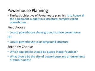
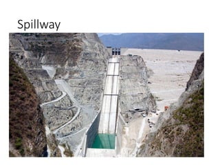
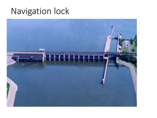
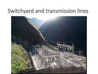
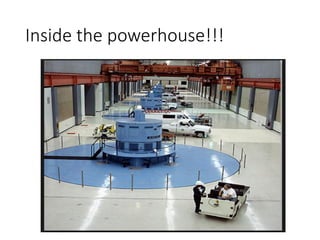
2. Powerhouse??
• Power house: The structure that houses generators
and turbines.
Requirements of powerhouse
planning:
• Functional efficiency
• Aesthetic beauty
3. Determining location of powerhouse
The factors affecting powerhouse location are:
• Location of spillway(when powerhouse is located
adjacent to the dam)
• Location of navigation locks(on navigation projects)
• Foundation conditions
• Valley width
• River channel conditions below dam
• Accessibility
• Location of switchyard and transmission lines
4. Powerhouse Planning
• The basic objective of Powerhouse planning is to house all
the equipment suitably in a structural complex called
powerhouse.
First choose
• Locate powerhouse above ground-surface powerhouse
OR
• Locate powerhouse as underground structure
Secondly Choose
• Which equipment should be placed indoor/outdoor?
• What should be the size of powerhouse and arrangements
of various units?
15. Powerhouse Structure
• There are three main divisions:
1. Sub-structure
2. Intermediate structure
3. Super structure
16. General arrangement of
powerhouse
• Sub-structure
Situated below the turbine level
Includes draft tube, tail water channel, natural drainage
pipes of waste water, drainage galleries etc.
Transmits the load of above structure to foundation strata
Usually a massive concrete structure
17. General arrangement of
powerhouse
• Intermediate structure
It extends from top of draft tube to the top of generator
foundation.
Includes scroll casing, galleries for auxiliary machines and
governor servo-motor system.
Turbine floor lies below generator floor and is accessible
through stairs.
18. General arrangement of
powerhouse
• Super-structure
It extends from generator floor called main floor up to the
roof top.
It includes generators, governors, control room, the exciters,
and auxiliary equipment such as those needed for
ventilation and cooling.
It consists of walls and roof with main travelling gantry
crane at roof level.
19. General dimension calculation of
powerhouse
• The super structure of powerhouse has the following three
bays.
1. Machine hall or unit bay
2. Erection or loading bay
3. Control bay
21. General dimension calculation of
powerhouse
Machine hall or unit bay
Length:
Depends on number of units, distance between units and
size of machines.
Usually approximate distance is 4.5 to 5 D where D is
turbine outlet diameter with added minimum clearance of 2
to 3 m as minimum clearance.
Center to center distance between units is taken as 5D+2.5
m.
22. General dimension calculation of
powerhouse
Machine hall or unit bay
Width:
It is usually taken as:
width of one unit+ extra passage from the wall
Where,
• Extra passage from the wall=2.5m for the movement
Excessive width may cause increase in size of girder or the
crane, supporting beam, column and the roof covering.
24. General dimension calculation of
powerhouse
Machine hall or unit bay
Height:
It is fixed by head room requirements(about 2 to 2.5 m) of
crane operation.
Height should be enough to enable cranes to lift the rotor of
the generator or the runner of the turbine clear off the floor
without the other machine sets obstructing.
Height=clearance space+ depth of crane girder+ head room
for operating cabin.
26. General dimension calculation of
powerhouse
Erection or loading bay
• Space where heavy vehicles can be loaded and un-loaded;
dismantled machine parts can be placed and small
assembling of equipment can be done.
• Should be sufficient t receive large parts like rotor and
runner.
• Its width should be at least equal to the distance between
machine center lines.
28. General dimension calculation of
powerhouse
Control bay
It houses main control and other equipment.
It may be adjacent to the unit as practiced commonly.
It sends instructions to operation room from where the
operation control is achieved