SlideShare a Scribd company logo
1 of 88
CONE BEAM
COMPUTED
TOMOGRAPHY
Guided by: Dr. Navneet Sharma
Presentation by: Ayushi Gautam
VOLUME ACQUISITION
CBCT
PART 1
Introduction
• Cone beam computed tomography, also known as CBCT, was originally developed for
angiography in the early 1980s.
• The first dental and maxillofacial units were commercially introduced in the late 1990s and
early 2000s.
• Unlike other extraoral dental imaging procedures, like panoramic and cephalometric
radiography, CBCT acquires data volumetrically providing three-dimensional (3D) radiographic
imaging for the assessment of the dental and maxillofacial complex facilitating dental
diagnosis.
• The role of maxillofacial CBCT has also expanded to image guidance of operative and surgical
procedures and also in additive manufacturing of biomodels and surgical guides.
• There are three processes in CBCT imaging: image production, visualization and
interpretation.
Principles of CBCT
• In all CT techniques, a collimated x ray source and a detector revolve around the
patient.
• The detector records photon attenuation by measuring the number of photons that
exit the patient and registers this information at several hundred angles through the
rotational arc.
• These recordings constitute the “raw data” which is then reconstructed by the
computer to form a 3D data set through which the image is derived.
• The basic component of the resultant greyscale is called Pixel.
• Intensity of each pixel is related to the intensity of the photons incident on the
detector.
• CBCT imaging is performed using a rotating gantry or C-arm
supporting the x-ray source and reciprocating the area
detector.
• A divergent x ray source, collimated as cone or a pyramid, is
directed through the region of interest and the residual
photons strike the detector on the opposite side.
• On activation, data are acquired from a series of sequential
exposures as the gantry rotates around a fixed axis of
rotation within the patient's ROI.
• The arc of the trajectory is ideally 360 degrees and can vary
from 180 to 720 degrees.
• The resultant raw data is also known as basis, frame, or raw
images
• The basis images appear in a complete series that is known as projection data.
• Because CBCT exposure incorporates the entire ROI, only one rotational scan of the
gantry is necessary to acquire enough data for volumetric image construction with
the help of various software programs.
• These software programs then form volumetric data set which is an image volume
that can be used to generate secondary reconstruction images in three orthogonal
planes (axial, sagittal, and coronal).
Components of image production
Three major components:
- X-ray generation
- X-ray detection
- Image reconstruction
• Maxillofacial CBCT systems can be distinguished operationally according to the orientation of
the patient during image acquisition.
Seated
According to function, CBCT devices can also be categorized according to functionality and
considered a dedicated unit (A and D) or a hybrid unit with panoramic (B) or panoramic and
cephalometric capability (C).
Standing Supine
X ray Generation
• CBCT imaging is technically simple as only a
single scan of the patient is made to acquire
a projection data set.
• Numerous other clinically important
parameters affect both image quality and
patient radiation dose in X-ray generation.
Patient Stabilization
• CBCT examinations are made with the patient sitting, standing, or supine based on
the type of unit.
• Supine units are physically larger, have a greater physical footprint so they may not
be accessible for patients with some physical disabilities.
• On the other hand, standing units may not be able to be adjusted to a height low
enough to accommodate wheelchair-bound patients.
• Hence, seated units are the most comfortable.
• Immobilization of the patient's head is more important than patient positioning
because any head movement degrades the final image. Immobilization of the head is
achieved by using some combination of a chin cup, bite fork, or other head restraint
mechanism.
X-Ray Generator
• X-ray generation may be continuous or pulsed to coincide with the detector
activation (preferably pulsed).
• X ray production being pulsed means that actual exposure time can be substantially
less than scanning time.
• This considerably reduces patient radiation dose.
• The ALARA (As Low As Reasonably Achievable) principle of dose optimization
necessitates that CBCT exposure factors should be adjusted on the basis of patient
size and specific diagnostic task.
• This is done by appropriate selection of tube current (milliamperes [mA]), tube
voltage (kilovolt peak [kVp]), or both.
• In some cases, exposure time also can be adjusted to change scan time.
Scan volume
• Scan volume primarily depend on the detector size and shape, the beam projection
geometry, and the ability to collimate the beam.
• The shape of the scan volume can be either cylindrical or spherical.
• Collimating the primary x-ray beam limits radiation exposure to the ROI.
• It reduces unnecessary exposure to the patient and produces the best images by
minimizing scattered radiation, which degrades image quality.
Classification of CBCT units according to Field of view (FOV)
(A) Large FOV scans provide images of the entire craniofacial skeleton, enabling cephalometric analysis.
(B) Medium FOV scans image the maxilla or mandible or both. (C) Focused or restricted FOV scans
provide high-resolution images of limited regions. (D) Stitched scans from multiple focused FOV scans
provide larger regions of interest to be imaged from superimposition of multiple scans.
• Two approaches have been introduced to enable scanning of an ROI greater than the
FOV of the detector.
1. One method involves obtaining data from two or more separate scans and
superimposing the overlapping regions of the CBCT data volumes using
corresponding fiducial reference landmarks that is known as either “bioimage
registration” or “mosaicing”.
Software is used to fuse adjacent image volumes (“stitching” or “blending”) to
create a larger volumetric data set either in the horizontal or in the vertical dimension,
the only disadvantage of stitching overlapped regions is that such overlapped regions
are imaged twice so the radiation dose is more in these areas.
• Increasing Field of View (FOV) by
“Stitching” Volumetric Data Sets.
Units may use this technique to increase
either the vertical (A) or the horizontal (B)
FOV. Shown here are adjacent (orange and
blue) volumetric data sets
• A second method to increase the height or width of the FOV using a small area detector is to offset
the position of the detector, collimate the beam asymmetrically, and scan only half the patient's ROI
in each of the two offset scans.
(A) Conventional geometric arrangement whereby the central ray of the x-ray beam from the focal source is directed through
the middle of the object to the center of the FPD. The resultant image is limited to the region of the detector (dentition in
this case). (B) Alternative method increasing image size involves shifting the location of the flat panel imager and collimating
the x-ray beam laterally to extend the FOV object.
Scan Factors
• The number of images that constitute the projection data from the scan is determined by the
detector frame rate (i.e., the number of images acquired per second),the completeness of the
trajectory arc (180 to 360 degrees), and the rotation speed of the source and detector.
• Higher frame rates increase the signal-to noise ratio, producing images with less noise and
reducing metallic artifacts but takes longer scan time and more exposure time for the patient.
• Most CBCT units have fixed scan arcs. Fixed rotation angle units may be a full 360 degrees or
partial trajectory arcs.
• It is desirable to reduce CBCT scan times to as short as possible to reduce motion artifact
resulting from patient movement.
Image Detectors
• Current CBCT units can be divided into two groups based on detector type: (1) image
intensifier tube/charge-coupled device (II/CCD) combination or (2) flat panel
detectors (FPDs).
• II/CCD units are usually larger and bulkier and result in circular basis image areas
(spherical volumes) rather than rectangular ones (cylindrical volumes) produced by
FPDs.
• FPDs employ an “indirect” detector based on a large area solid-state detector panel
coupled to an x-ray scintillator layer.
• More recently, large complementary metal oxide semiconductor technology arrays
have also been used.
Voxel Size
• The spatial resolution (details of the CBCT image) is determined by the dimensions of
individual voxels produced in formatting the volumetric data set.
• CBCT units in general provide voxel resolutions that are isotropic which means equal in
all three dimensions.
• The principal determinants of nominal voxel size in a CBCT image are the matrix and
pixel size of the detector.
• Both the focal spot size and the geometric configuration of the x-ray source are
important to determine the degree of geometric unsharpness, a limiting factor in
spatial resolution.
• In maxillofacial CBCT imaging, the detector position is limited because it must be
located far enough from the patient's head so that it freely rotates unobstructed by
the patient's shoulders.
• Limitations also exist in extending the source-to-object distance because this
increases the size of the CBCT unit.
• Reducing source-to-object distance produces a magnified projected image on the
detector, increasing potential spatial resolution.
Grayscale
• The ability of CBCT imaging to display differences in photon attenuation is related to
the ability of the detector to reveal subtle contrast differences.
• n is related to the ability of the detector to reveal subtle contrast differences. This
parameter is called the bit depth of the system.
• All currently available CBCT units use detectors capable of recording grayscale
differences of 12 bits or greater.
Reconstruction
• Although a single acquisition rotation may take less than 20 seconds, it produces 100 to more
than 600 individual projection frames, each with more than 1 million pixels with 12 to 16 bits
of data assigned to each pixel.
• These data are processed to create a volumetric data set composed of cuboidal volume
elements (voxels) by a sequence of software algorithms in a process called primary
reconstruction.
• Subsequently, visual orthogonal (i.e., perpendicular) images are reformatted by sectioning the
volumetric data set, referred to as secondary reconstruction.
• The reconstruction of these data is computationally complex. To facilitate data handling, data
may be acquired by one computer (acquisition computer) and transferred by an Ethernet
connection to a processing computer (workstation).
• The reconstruction process consists of two stages, each comprising numerous
steps Image Acquisition and Reconstruction.
The acquisition stage involves acquisition
of individual basis projections and
subsequent modification of these images
to correct for inconsistencies. Image
correction is sequential and consists of the
removal of signal voids from individual or
linear pixel defects, image normalization
by histogram equalization so that a full
range of voxel intensity values are used,
and removal of inherent electronic
detector artifacts. After correction, images
undergo reconstruction, which includes
converting the corrected basis projection
images into sinograms and application of
the Feldkamp reconstruction to the
corrected filters to the image and use of
back-projection techniques to reconstitute
the image.
• 1. Preprocessing stage: The preprocessing stage is performed at the acquisition computer.
After the multiple planar projection images are acquired, these images must be corrected for
inherent pixel imperfections, variations in sensitivity across the detector, and uneven exposure.
• 2. Reconstruction stage: The remaining data-processing steps are performed on the
reconstruction computer. The corrected images are converted into a special representation
called a sinogram, a composite image developed from multiple projection images. This process
of generating a sinogram is referred to as the Radon transformation.
The final image is reconstructed from the sinogram with a filtered back
projection algorithm for volumetric data acquired by CBCT imaging; the most widely used
algorithm is the Feldkamp algorithm. This process is referred to as inverse Radon transformation.
When all slices have been reconstructed, they are combined into a single volume for visualization.
Cone Beam Computed Tomography (CBCT) Detector
Preprocessing.
The first step of CBCT detector preprocessing is offset
correction. This is accomplished by pixel-wise
subtraction of an individual offset value computed by
averaging over a series of up to 30 dark images. The
second step is the linear gain calibration, consisting of
dividing each pixel by its individual gain factor. The gain
factors are obtained by averaging a sequence with up to
30 images of homogeneous exposures without any
object between x-ray source and detector. The gain
sequence is first offset corrected with its own sequence
of dark images. The next procedure is the defect
interpolation. Each pixel that shows unusual behavior,
either in the gain image or in the average dark sequence,
is marked in a defect map. The gray values of pixels
classified as defective in this way are computed by linear
interpolation along the least gradient descent. For flat
panel detectors, there is usually an additional procedure
to correct for temporal artifacts. These arise in such
detectors because both the scintillator and the
photodiodes exhibit residual signals.
• Reconstruction times vary depending on the acquisition parameters,
hardware and software used.
• Reconstruction should be accomplished in an acceptable time to facilitate
workflow. (<5 minutes)
Clinical considerations
• Patient Selection Criteria:
The principal tenet of the ALARA principle must be applied: There should be
justification of the exposure to the patient so that the total potential diagnostic
benefits are greater than the individual detriment radiation exposure might cause.
A CBCT image should be used only when a lower dose examination, such as a periapical
or panoramic view, cannot provide the necessary information for patient diagnosis and
treatment.
CBCT imaging should be used as an adjunctive diagnostic tool to existing dental imaging
techniques for specific clinical applications, not as a screening procedure.
• Patient Preparation:
Patients should be escorted into the scanner unit and provided with appropriate
personal radiation barrier protection before head stabilization.
It is recommended that at least a leaded torso apron be applied correctly (above the
collar) to the patient.
Immediately before the scan, the patient should be asked to remove all metallic objects
from the head and neck areas, including eyeglasses, jewelry (including earrings and
piercings), and metallic partial dentures.
Image quality is severely degraded by head movement, so it is important to obtain
patient compliance.
• Imaging Protocol:
An imaging protocol is a set of technical exposure
parameters for CBCT imaging that depend on the
specified purpose of the examination.
An imaging protocol is developed to produce
images of optimal quality with the least amount
of radiation exposure to the patient.
Operators should be aware of the effects of all
parameters on image quality and patient dose
when choosing imaging protocols.
Icons in light green show the selected settings for a
medium field of view (80 mm × 80 mm) with a
rotation trajectory of 360-degrees, and a standard
nominal resolution. The selected exposure factors
(90 kV, 4 mA) can be adjusted to optimize for patient
size. The scan time and the radiation dose
(computed tomography dose index, CTDI) for these
settings are displayed in the top left corner.
• Exposure Settings:
The quality and quantity of the x-ray beam depend on tube voltage (kVp) and tube
current (mA).
Some CBCT manufacturers provide units with fixed, nonadjustable exposure settings,
whereas others incorporate “preset” exposure settings.
A recent CBCT innovation is incorporation of automatic exposure control (AEC) as a
dose reduction strategy to optimize patient doses.
When exposure reduction is necessary to compensate for differences in patient size,
mA changes are preferable to kVp changes as the increase in noise for a given dose
reduction is smaller for the former. mA adjustments affect effective dose
proportionately.
Exposure parameters should be appropriate for both the given patient size and the
diagnostic task that motivated image selection.
Spatial Resolution:
Spatial resolution refers to the ability of an image to reveal fine detail.
It is determined primarily by detector nominal pixel size, beam projection geometry,
patient scatter, detector motion blur, fill factor), focal spot size, number of basis
images, and reconstruction algorithm.
Scan Time and Number of Projections:
Adjusting the detector frame rate to increase the number of basis image projections
results in reconstructed images with fewer artifacts and better image quality but
increasing the number of projections requires longer primary reconstruction times and
increases patient radiation exposure proportionately.
Pictorial Plot of the Effect of Number of Basis
Projection Images and Size of Field of View
(FOV) on Image Quality. Increasing number of
projections in one 360- degree scan (x-axis)
provides more data and reduces image noise;
however, it increases patient dose
proportionately. Reducing the number of
projections creates undersampling and
produces streaks. Minimizing the FOV (y-axis)
reduces patient exposure and resultant
scatter radiation and results in images with
increased contrast and decreased noise.
Scanning Trajectory:
Reconstructed images from incomplete, limited, or truncated scanning trajectories of
less than 360 degrees may have limited-angle artifacts because of missing information.
Field of View:
Collimation of the CBCT primary x-ray beam by adjustment of the FOV enables
limitation of the x-radiation to the ROI. Reduction of the FOV to the ROI improves
image quality because of reduced scattered radiation.
Image Artifacts
An artifact is any distortion or error in the image that is unrelated to the subject being
studied.
Artifacts can be classified according to their etiology:
• Inherent Artifacts:
Artifacts can arise from limitations in the physical processes involved in the acquisition
of CBCT data.
The beam projection geometry of CBCT, reduced trajectory rotational arcs, and image
reconstruction methods produce the following three types of artifacts:
a) Scatter
b) Partial volume averaging
c) Cone beam effect
• Scatter results from x-ray photons that are diffracted from their
original path after interaction with matter. Scatter causes streak
artifacts similar to artifacts of beam hardening.
• Partial volume averaging is a feature of both MDCT and CBCT
imaging. It occurs when the selected voxel size of the scan is
larger than the size of the object being imaged.
• The cone beam effect is a potential source of artifacts,
especially in the peripheral portions of the scan volume.
Because of the divergence of the x-ray beam as it rotates around
the patient in a horizontal plane, structures at the top or bottom of
the image field are exposed only when the x-ray source is on the
opposite side of the patient. The result is image distortion,
streaking artifacts, and greater peripheral noise.
This picture shows marked graininess
or quantum noise caused by
contamination of detector signal by
scatter radiation.
• Procedure-Related Artifacts:
Undersampling of the object can occur when too few basis
projections are provided for image reconstruction or when
rotational trajectory arcs are incomplete.
A reduced data sample leads to misregistration, sharp
edges, and noisier images as a result of aliasing, which
appear as fine striations in the image.
Typically, scanner-related artifacts appear as circular or ring
streaks resulting from imperfections in scanner detection or
poor calibration.
• Introduced Artifacts:
As an x-ray beam passes through an object, lower
energy photons are absorbed in preference to higher
energy photons. This phenomenon is called beam
hardening.
This results in two types of artifact:
(1) distortion of metallic structures as a result of
differential absorption, known as a cupping artifact.
(2) streaks and dark bands, which, when present
between two dense objects, create extinction or
missing value artifacts
• Patient Motion Artifacts:
Patient motion can cause misregistration of data, which appear as double contours in
the reconstructed image. This problem can be minimized by restraining the head and
using as short a scan time as possible.
Motion Artifacts. Patient motion during the scanning exposure can result in misregistration
artifacts, which appear as double contours in the reconstructed image as demonstrated in the
axial (A), coronal (B), and sagittal (C) planes.
Strengths and Limitations
Strengths:
• Size and Cost
• Fast Acquisition
• Submillimeter Resolution
• Relatively Low Patient Radiation Dose
• Interactive Analysis
Limitations:
• Image Noise
• Poor Soft Tissue Contrast
VOLUME PREPARATION
CBCT
PART 2
Introduction
• Cone beam computed tomographic (CBCT) imaging is an inherently volumetric
image-capture technology providing a data set from which digital images are
reformatted and presented on a display monitor. Visualization of CBCT data therefore
necessitates that clinicians are familiar with software-assisted volumetric review.
• This part focuses on the interaction and use of the subsequent volumetric data for
image interpretation, and task-specific applications.
Stages in Volumetric Data Display
• Most software programs display the CBCT volumetric data set as secondary two-dimensional
(2D) contiguous reconstructed images in three orthogonal planes (axial, sagittal, and coronal)
at a default thickness.
• CBCT data should be considered as a volume that must be analyzed in its entirety, and from
which selected images are extracted to document the findings.
• Four stages provide an efficient and consistent systematic methodologic approach to optimize
CBCT image display before image interpretation:
1. Reorient data
2. Correct data
3. Explore data
4. Format data
Reorient data
• One of the advantages of CBCT acquisition is that the resultant volumetric data set
can be reoriented in relation to three orthogonal planes using imaging software.
• The entire volume can be reoriented such that the patient's anatomic features are
aligned to fixed orthogonal coordinates.
• This stage is particularly important for aligning subsequent cross-sectional, trans axial
images perpendicular to the structure of interest.
• It helps to visualize single tooth pathology, to measure the maximal height and width
of the residual alveolar ridge, to compare temporomandibular joint (TMJ) condylar
morphology, or to perform a craniofacial analysis.
• Optimize Displayed Images
The overall density and contrast of orthogonal images varies between CBCT units and
within the same unit depending on the patient size, degree of edentulism, and scan
parameters selected.
Hence, to optimize image presentation and facilitate diagnosis, it is often necessary to
adjust contrast (window width) and brightness (window level) parameters to favor
bony structures.
After this, secondary algorithms (e.g., annotation, measurement, magnification) can be
applied with confidence.
Effect of Image Enhancement on
Cone Beam Computed Tomographic
Images.
The visual effect of three sequential
adjustments on a multiplanar
reformation cross-sectional image. (A)
Default image after interpolation
algorithm—smoothens edges of
cortical bone but adds blur to high-
contrast structures. (B) Adjustment of
window level and width to bone
preset (W/L: 3000/500). (C) Addition
of mild sharpen algorithm.
Explore data
• It is impractical to display all slices on one display format because there are
numerous contiguous orthogonal images in each plane.
• Therefore each series must be reviewed dynamically by scrolling through the
consecutive orthogonal image “stack.”
• This is referred to as navigating through the volume in a “cine” or “paging” mode.
• Scrolling is performed craniocaudally, and the in reverse direction slowing down in
complex areas and is done in two planes.
Format Data
• All CBCT software, be it either proprietary acquisition and display original equipment
manufacturer (OEM) or commercial third-party display programs, are capable of
many formatting options.
• Each of these is directed toward visualizing specific components of the volumetric
data set.
• There are two basic format options:
• Multiplanar reformation
• Volumetric rendering
Display Mode Options of Cone Beam
Computed Tomographic Volumetric
Data.
Display modes can be divided into two
categories: multiplanar reformation
(MPR) consisting of linear, curved
oblique, and serial trans axial images;
and volumetric images including ray
sum, comprising images of increased
section thickness, indirect volume
rendering (IVR), the most common of
which being maximum intensity
projection (MIP), and direct volume
rendering (DVR).
Multiplanar reformation:
• Because of the isotropic nature of acquisition, the volumetric data set can be
sectioned nonorthogonally to provide 2D planar images referred to as multiplanar
reformation (MPR).
• MPR modes include linear oblique, curved planar, and serial trans axial reformations.
• Linear oblique images are most often used to transect the mandibular condyle.
Curved planar images are generated by manually drawing a planning line or spline by
selecting multiple nodes along the centerline.
• Serial sequential images perpendicular to an arbitrary linear oblique or curved planar
MPR provide a dynamic representation of the anatomic structure, minimizing
parallax error. These images are referred to as trans axial, tangential or, most
commonly, cross-sectional images.
• Cross sectional images have two characteristics, a slice thickness and distance
between adjacent cross-sectional images (interslice interval).
Multiplanar Reformation (MPR).
A thick axial image (A) simulating an
occlusal image with an MPR oblique
curved line (white solid line) and
resultant “panoramic” image (B) and
serial cross-sectional, 1-mm-thick
images (C) of a potential implant site
in the lower left mandible. The axial
and panoramic images are used as
reference images to show the
location of the cross-sectional
images. The cross-sectional images
demonstrate the amount of lingual
undercut and location of the inferior
alveolar canal.
Volume Rendering
• Volume rendering allows visualization of volumetric data by selective display of voxels within
a data set as a 2D projection.
• Two specific techniques are commonly used: indirect volume rendering (IVR) and direct
volume rendering (DVR).
 Indirect volume rendering:
It is a complex process requiring selection of the intensity or density of the grayscale level of
the voxels to be displayed within an entire data set known as segmentation.
This process is technically demanding and computationally difficult, requiring specific software.
Two types of views are possible: views that are solid (surface rendering) and views that are
transparent (volumetric rendering).
Three-Dimensional Volumetric Surface Rendering. Manual segmentation is often accomplished by an
adjustable scale determining the upper and lower limit and range of intensity values to include in the
segmentation. The visual result of changes in this scale is displayed in “real time” so that the effects of
incremental changes can be visualized. The segmentation may be optimized to reveal the objects of
interest, including bone as a solid surface or shaded surface display (A) and bone and the dentition under
the bone as a transparency (B) using volumetric imaging.
 Direct volume rendering:
It is a much simpler process that involves selecting an arbitrary threshold of voxel intensities,
below or above which all gray values are removed.
The most commonly used techniques are ray sum and maximum intensity projection (MIP).
The slice thickness of orthogonal or MPR images can be “thickened” by increasing the
number of adjacent voxels included in the display that creates an image slab that represents
a specific volume of the patient, referred to as a ray sum.
In contrast to conventional radiographs, these ray sum images are without magnification and
parallax distortion.
But, this technique uses the entire volumetric data set, and interpretation is negatively
affected by “anatomic noise”—the superimposition of multiple structures—also present in
conventional projection radiography.
Ray Sum Images. (A) An axial projection is used as the reference image. A section slice is identified that in
this case corresponds to the midsagittal plane, and the thickness of this slice is increased to include both
left and right sides of the volumetric data set. As the thickness of the “slab” increases, adjacent voxels
representing elements such as air, bone, and soft tissues are added. (B) The resultant image generated
from a full-thickness ray sum provides a simulated lateral cephalometric image.
Two-Dimensional Projections Generated With
Cone Beam Data Set.
This patient had an asymmetry of one side of
the face. Ray sum reformation of the cone beam
computed tomographic data was performed to
provide multiple conventional images, such as
the lateral cephalometric (A), frontal
cephalometric or posteroanterior (B), and
panoramic (C) projections
• Maximum intensity projection (MIP) visualizations are achieved by evaluating each voxel
value along an imaginary projection ray from the observer's eyes within a particular volume of
interest and representing only the highest value as the display value.
Voxel intensities that are below an arbitrary threshold are eliminated
MIP images have great utility for demonstration of the location of impacted teeth, for TMJ
evaluation, for identification of fractures, for craniofacial analysis, for surgical follow-up, for
assessment of cervical spine anomalies, and for demonstration of soft tissue dystrophic
calcifications.
In this example, an axial projection (A) is used as the reference image. A projection ray is identified
throughout the entire volumetric data set along which individual voxels are identified, each with varying
grayscale intensity corresponding to various tissue densities, such as fat, muscle, air, and bone. The MIP
algorithm selects only the values along the projection ray that have the highest values (usually
corresponding to bone or metal) and represents this as only one pixel on the resultant image (B).
Interpretive Report
• Documentation of the CBCT procedure by the inclusion of an interpretive report is an
essential element of CBCT imaging and should form part of a patient's record.
• Patient diagnosis may often be complex, and management may involve numerous
practitioners.
• An interpretation report serves as the optimal method of communication of
interpretation findings for CBCT.
Task-Specific Applications
• Diagnosis and Preoperative Assessment:
 Implant Site Assessment : Perhaps the greatest impact of CBCT has been on the
planning of dental implant placements.
The most useful series of images for implant site assessment include the axial,
reformatted panoramic, and cross-sectional images at the specific location.
Cone Beam Computed Tomographic Imaging for Implant Site Assessment.
A curved planar multiplanar reformation (MPR) is accomplished by aligning
the long axis of the imaging plane with the dental arch (A), providing a
regional panorama-like thin-slice image (B). In addition, serial thin-slice trans
axial images are often generated perpendicular to the curved planar MPR
(C), which are useful in the assessment of specific morphologic features,
such as the location of the inferior alveolar canal (shown with a white dot)
for implant site assessment and for allowing measurement of the available
alveolar bone height and width (solid line)
Use of a Radiographic Template. Plastic intraoral appliances provide fiducial radiographic landmarks that can be used to
correlate proposed clinical location and angulation of implants with the available alveolar bone. The axial (A) and
panoramic (B) projections provide an overview of location, whereas serial cross-sectional images (C) indicate alveolar
bone height. In this example of an edentulous mandible, the radiograph has two markers at proposed implant sites; the
1-mm-thick trans planar images at 3-mm intervals of the mandibular anterior region (C) indicate that although the right
trajectory is optimal (upper left cross-sectional image), the proposed placement trajectory of the right implant (lower
left) is too far buccal to engage the available bone.
 Endodontics: The use of CBCT imaging in endodontics is indicated in the following
clinical situations-
• Patients who present with contradictory or nonspecific clinical signs and symptoms
associated with untreated or previously endodontically treated teeth.
• For the initial treatment of teeth with the potential for extra canals and suspected
complex morphology, such as mandibular anterior teeth, and maxillary and
mandibular premolars and molars, and dental anomalies.
• For intra-appointment identification and localization of calcified canals.
• If clinical examination and 2D intraoral radiography are inconclusive in the detection
of vertical root fracture.
• When evaluating the non-healing of previous endodontic treatment to help
determine the need for further treatment, such as nonsurgical, surgical, or
extraction.
• For nonsurgical retreatment to assess endodontic treatment complications, such as
overextended root canal obturation material, separated endodontic instruments, and
localization of perforations.
• For presurgical treatment planning to localize root apex/apices and to evaluate the
proximity to adjacent anatomical structures.
• For the surgical placement of implants.
• For diagnosis and management of limited dentoalveolar trauma, root fractures,
luxation, and/or displacement of teeth, and localized alveolar fractures, in the
absence of other maxillofacial or soft tissue injury that may require other advanced
imaging modalities.
• For the localization and differentiation of external and internal resorptive defects and
the determination of appropriate treatment and prognosis.
Cone Beam Computed Tomographic (CBCT) Imaging for
Endodontics.
Numerous endodontically related conditions can be
demonstrated in high resolution with restricted field of view
CBCT imaging, including periapical conditions (A); periodontal,
periapical, and sinus disease (B); and root fracture and
associated alveolar bone loss (C).
 Orthodontics and Three-Dimensional Cephalometry: CBCT imaging is used in the
diagnosis, assessment, and analysis of maxillofacial orthodontic and orthopedic
anomalies.
CBCT imaging facilitates surgical exposure and planning of subsequent movement.
Other applications include the assessment of palatal morphologic features and
dimensions, tooth inclination and torque, characterization of alveolar bone for
orthodontic mini-implant placement, and determining available alveolar bone width for
buccolingual movement of teeth.
CBCT imaging also provides adequate visualization of the TMJ, pharyngeal airway
space, and soft tissue relationships.
• CBCT imaging provides two unique contributions to orthodontic practice:
i. Numerous linear images currently used in orthodontic diagnosis, cephalometric
analysis, and treatment planning can be created from a single CBCT scan. This
capability provides for greater clinical efficacy.
ii. CBCT data can be reconstructed to provide unique, previously unavailable images.
The numerous potential benefits to 3D cephalometry include demonstrating and
characterizing asymmetry and anteroposterior, vertical, and transverse
dentoskeletal discrepancies, incorporating the soft tissue integument, and the
potential for assessment of growth and development.
 Mandibular Third Molar Position:
The relationship of the IAC to the roots of mandibular third molar teeth is important
when considering extractions and attempting to minimize the likelihood of nerve
damage that may lead to permanent loss of sensation to one side to the lower lip.
Accurate assessment of the position of the IAC in relation to the impacted third molar
may reduce injuries to this nerve.
Cone Beam Imaging for Third Molar Assessment.
Third-party software used to demonstrate the location of the inferior alveolar canal (IAC) (green).
Nonannotated (A) and annotated (B) panoramic multiplanar reformation reformatted, volumetric
transparency reconstruction (C) images with corresponding nonannotated (D) and annotated field of view (E)
cross-sectional images at 1-mm intervals. Crosssectional slices with the IAC traced (green). All images
demonstrate the close proximity and course of the IAC in relation to the root of the left mandibular,
horizontally bony impacted and unerupted third molar.
 Temporomandibular Joint:
CBCT imaging provides multiplanar and potentially 3D images of the condyle and
surrounding structures to facilitate analysis and diagnosis of osseous morphologic
features and joint space and function.
Imaging can depict the features of degenerative joint disease and developmental
anomalies of the condyle, ankylosis, and rheumatoid arthritis.
Cone Beam Computed Tomographic Imaging of
the Temporomandibular Joint (TMJ).
Corrected coronal (A) and sagittal (B) images of a
right TMJ with erosive defects on the superior
cortical surface of the condyle associated with
mild degenerative joint disease.
 Maxillofacial Pathoses:
CBCT imaging can assist in the assessment of many conditions of the jaws, most
notably dental conditions such as impacted canines and supernumerary teeth,
fractured or split teeth, periapical lesions, and periodontal disease.
Benign calcifications (e.g., tonsilloliths, lymph nodes, salivary gland stones) can also be
identified by location.
Although CBCT imaging does not provide suitable soft tissue contrast to distinguish the
contents of paranasal soft tissue attenuations, the morphologic characteristics and
extent of these lesions are particularly well seen (e.g., mucous extravasation cyst).
CBCT imaging is particularly useful for assessment of trauma and for visualizing the
extent and degree of involvement of benign odontogenic or nonodontogenic cysts and
tumors as well as osteomyelitis.
Cone Beam Computed Tomographic Imaging of Mandibular
Fractures.
Use of maximum intensity projection (MIP) in the assessment of
complex mandibular fractures. (A) Oblique thin slab multiplanar
reformation image with MIP application demonstrates a simple,
slightly displaced fracture of the right parasymphyseal region.
(B) Coronal thin-slab MIP image demonstrates a comminuted
displaced left subcondylar neck fracture.
Cone Beam Computed Tomographic Imaging of Maxillofacial
Pathology.
(A) Cropped reformatted ray sum panoramic view. (B) Axial
slice at level of red horizontal line on panoramic view and
outline for midportion of cross-sectional images. (C) Serial 1-
mm-thick cross-sectional slices (of unilocular well-defined
hypodensity) in the left premolar mandibular body of a
patient in the mixed dentition phase.
Treatment Planning and Virtual Simulations
• The key feature of CBCT image output that makes systems interoperable is the use of
image files that are conformant with the Digital Imaging and Communications in
Medicine (DICOM) standard file format.
• Treatment planning for a potential implant site involves an interplay of considerations
of both surgical and prosthetic requirements.
• In implant planning, software can be used to select and direct the placement of
implant fixtures either directly by the use of image-guided navigation or indirectly via
the construction of restrictive surgical guides.
Virtual Simulation Planning for Implant Placement.
(A) Reformatted thin section panoramic of a partially
dentate maxilla shows the alignment of the two
virtual implant bodies (yellow outline) in relation to
the radiographic markers providing the planned
occlusal surface of the right first premolar and left
second premolar teeth. (B) Axial image showing the
buccopalatal position of the right implant (yellow
outline) in the residual alveolar ridge. (D) Composite
cone beam computed tomographic and optical
intraoral surface scan of the teeth and mucosa (silver)
shows the buccopalatal emergence profile (yellow
solid line) and position (implant outline in solid
yellow). Software also allows the use of overlay
prosthetic tools, such as (1) surgical confidence
marker (dark blue outline around each implant used
to identify 0.5-mm surgical tolerance limits); (2)
tapering drill confidence limit, shown on the apical
portion of the implant (space between yellow implant
and blue outline, C); and (3) soft tissue collar (white
outline, C).
• Image fusion is the process of
integration of two imaging data sets.
Most commonly, CBCT volumes are fused
with extraoral facial (photographic) or
intraoral (impression) optical data.
After registration, numerous options allow
interaction with the data sets either
independently or in toto.
Fusion Image. Right lateral (A), 45-degree (B), and frontal (C)
three-dimensional (3D) anatomic views demonstrate image
fusion possibilities. (A) Volumetric cone beam computed
tomographic (CBCT) rendering. (B) CBCT data fused with high-
resolution intraoral optical surface scanning of the teeth. (C)
CBCT intraoral optical scan and facial digital photographs
fused to form a composite 3D image set.
Image-Guided Surgery and Additive
Manufacturing
• Imaged-guided surgery refers to techniques that translate software-derived virtual
surgical plans developed from virtual simulations to the surgical environment.
• Two concepts for image-guided surgery have been developed:
a. The first concept involves the fabrication of a plastic drilling or surgical template
based on a virtual treatment plan.
b. The second concept incorporates expensive navigation systems that implement the
techniques of frameless stereotaxy. This real-time, in operatory, display-driven
virtual guidance of surgical tools is based on the registration of the surgical
instrument with the virtual patient as demonstrated by CBCT data
• Additive manufacturing (AM) is a broad term to describe a group of related
processes and techniques used to fabricate physical scale models directly from 3D
computer-assisted design data.
• 3D printing is but one of a range of AM processes in which material is extruded
through fine nozzles in layers to create an object—similar to inkjet printer print
heads.
• In maxillofacial imaging, the most obvious and widespread clinical application of the
use of AM has been in the fabrication of surgical guides to assist in dental implant
placement.
• However, biomodels, customized plastic dimensionally accurate anatomic models of
the maxillofacial skeleton, can also be fabricated.
Additive Manufacturing for Orthognathic
Surgery.
(A) Three-dimensional volumetric
reconstruction of the maxilla and mandible after
virtual surgery combining maxillofacial cone
beam computed tomographic data and optical
surface scans of the dentition. Note the wafer
separating the maxillary and mandibular
dentition that is used as a surgical guide to
confirm the final relationship of the dentition.
(B) Biomodel of the maxillofacial complex after
virtual surgery with interposed plastic surgical
stent. Modeling was performed to provide a
physical model with which to confirm the actual
surgery and fit of the surgical guide.
Additive Manufacturing In-Office Printing. (A) Example of in-office threedimensional resin based printer (NP1,
NewPro3D, Burnaby, BC, Canada) using a proprietary modification of digital light processing technology (ILI Technology).
(B) Schematic showing ILI technology. An accurate resin object (formed object), such as a biomodel or surgical guide, is
created by projection of a light pattern (light projector) onto a wettable membrane between the photo-curing resin
(liquid resin) and the light source. The object is created by sequential layering of photo-polymerized resin with upward
translation of the build platform.
Conclusion
• CBCT technology has expanded maxillofacial CBCT imaging from diagnosis and image
guidance of operative and surgical procedures into 3D printing.
• The use of CBCT has allowed greater predictability in the diagnosis and subsequent
care of patients, especially those with complex conditions.
• This imaging tool brings with it an increased practitioner responsibility in the
performance, optimal visualization, and interpretation of volumetric data sets.
References:
o White and Pharoah's Oral Radiology Principles and Interpretation
8TH EDITION
Thank you!

More Related Content

What's hot

RADIOGRAPHIC IMAGING FOR DENTAL IMPLANT ASSESSMENT
RADIOGRAPHIC IMAGING FOR DENTAL IMPLANT ASSESSMENTRADIOGRAPHIC IMAGING FOR DENTAL IMPLANT ASSESSMENT
RADIOGRAPHIC IMAGING FOR DENTAL IMPLANT ASSESSMENTDr. Monali Prajapati
 
Basic applications of CBCT
 Basic applications of CBCT Basic applications of CBCT
Basic applications of CBCTDrMohamedEkram
 
Parallel angle technique vs bisecting angle technique.
Parallel angle technique vs bisecting angle technique.Parallel angle technique vs bisecting angle technique.
Parallel angle technique vs bisecting angle technique.salman zahid
 
CBCT in Implants- Summary
CBCT in Implants- SummaryCBCT in Implants- Summary
CBCT in Implants- Summaryghidalawand
 
Cbct in endodontics ppt
Cbct in endodontics pptCbct in endodontics ppt
Cbct in endodontics pptDr kausar banu
 
Benefits of cbct in implant planning
Benefits of cbct in implant planningBenefits of cbct in implant planning
Benefits of cbct in implant planningUE
 
Cone beam ct
Cone beam ctCone beam ct
Cone beam ctnivedhanive8
 
RADIO VISIO GRAPHY, Dr Anirudh Singh Chauhan
RADIO VISIO GRAPHY, Dr Anirudh Singh ChauhanRADIO VISIO GRAPHY, Dr Anirudh Singh Chauhan
RADIO VISIO GRAPHY, Dr Anirudh Singh ChauhanAnirudh Singh Chauhan
 
Review on the applications of ultrasonography in dentistry - Dr Sanjana Ravindra
Review on the applications of ultrasonography in dentistry - Dr Sanjana RavindraReview on the applications of ultrasonography in dentistry - Dr Sanjana Ravindra
Review on the applications of ultrasonography in dentistry - Dr Sanjana RavindraDr. Sanjana Ravindra
 
Electronic apex locator by dr.imran m.shaikh
Electronic apex locator by  dr.imran m.shaikhElectronic apex locator by  dr.imran m.shaikh
Electronic apex locator by dr.imran m.shaikhImran Shaikh
 
Temporomandibular joint imaging
Temporomandibular joint imagingTemporomandibular joint imaging
Temporomandibular joint imagingDr Jinki Singha
 
Radiographs in endodontic diagnosis
Radiographs in endodontic diagnosisRadiographs in endodontic diagnosis
Radiographs in endodontic diagnosisliya thomas
 

What's hot (20)

Object localisation in dentistry
Object localisation in dentistryObject localisation in dentistry
Object localisation in dentistry
 
RADIOGRAPHIC IMAGING FOR DENTAL IMPLANT ASSESSMENT
RADIOGRAPHIC IMAGING FOR DENTAL IMPLANT ASSESSMENTRADIOGRAPHIC IMAGING FOR DENTAL IMPLANT ASSESSMENT
RADIOGRAPHIC IMAGING FOR DENTAL IMPLANT ASSESSMENT
 
Basic applications of CBCT
 Basic applications of CBCT Basic applications of CBCT
Basic applications of CBCT
 
Parallel angle technique vs bisecting angle technique.
Parallel angle technique vs bisecting angle technique.Parallel angle technique vs bisecting angle technique.
Parallel angle technique vs bisecting angle technique.
 
Extraoral radiography
Extraoral radiographyExtraoral radiography
Extraoral radiography
 
CBCT in Implants- Summary
CBCT in Implants- SummaryCBCT in Implants- Summary
CBCT in Implants- Summary
 
Digital imaging IN DENTISTRY
Digital imaging IN DENTISTRYDigital imaging IN DENTISTRY
Digital imaging IN DENTISTRY
 
Cbct
CbctCbct
Cbct
 
Cbct in endodontics ppt
Cbct in endodontics pptCbct in endodontics ppt
Cbct in endodontics ppt
 
Benefits of cbct in implant planning
Benefits of cbct in implant planningBenefits of cbct in implant planning
Benefits of cbct in implant planning
 
Panoramic radiography OPG
Panoramic radiography OPGPanoramic radiography OPG
Panoramic radiography OPG
 
Cone beam ct
Cone beam ctCone beam ct
Cone beam ct
 
RADIO VISIO GRAPHY, Dr Anirudh Singh Chauhan
RADIO VISIO GRAPHY, Dr Anirudh Singh ChauhanRADIO VISIO GRAPHY, Dr Anirudh Singh Chauhan
RADIO VISIO GRAPHY, Dr Anirudh Singh Chauhan
 
Review on the applications of ultrasonography in dentistry - Dr Sanjana Ravindra
Review on the applications of ultrasonography in dentistry - Dr Sanjana RavindraReview on the applications of ultrasonography in dentistry - Dr Sanjana Ravindra
Review on the applications of ultrasonography in dentistry - Dr Sanjana Ravindra
 
Socket Preservation _NIDM January 2011
Socket Preservation _NIDM January 2011Socket Preservation _NIDM January 2011
Socket Preservation _NIDM January 2011
 
Electronic apex locator by dr.imran m.shaikh
Electronic apex locator by  dr.imran m.shaikhElectronic apex locator by  dr.imran m.shaikh
Electronic apex locator by dr.imran m.shaikh
 
Cone beam
Cone beamCone beam
Cone beam
 
Temporomandibular joint imaging
Temporomandibular joint imagingTemporomandibular joint imaging
Temporomandibular joint imaging
 
Radiographs in endodontic diagnosis
Radiographs in endodontic diagnosisRadiographs in endodontic diagnosis
Radiographs in endodontic diagnosis
 
Dental operating microscope
Dental operating microscopeDental operating microscope
Dental operating microscope
 

Similar to CBCT.pptx

CBCT IN ORTHODONTICS
CBCT IN ORTHODONTICSCBCT IN ORTHODONTICS
CBCT IN ORTHODONTICSRoni Kuttickal
 
Cone beam computed tomography
Cone beam computed tomographyCone beam computed tomography
Cone beam computed tomographyVashi Narula
 
CBCT in dental practice
CBCT in dental practiceCBCT in dental practice
CBCT in dental practiceZana Hussein
 
Cone beam computed tomography (2)
Cone beam computed tomography (2)Cone beam computed tomography (2)
Cone beam computed tomography (2)Mohit Kapoor
 
CBCT IN ORTHODONTICS
CBCT IN ORTHODONTICSCBCT IN ORTHODONTICS
CBCT IN ORTHODONTICSDr. Hadia Arshad
 
CBCT in orthodontics
CBCT in orthodontics CBCT in orthodontics
CBCT in orthodontics DrAkshiSharma
 
Specialised Techniques in Oral Radiology
Specialised Techniques in Oral RadiologySpecialised Techniques in Oral Radiology
Specialised Techniques in Oral RadiologyIAU Dent
 
Technical aspects of dental CBCT - Dr. Kavan Gandhi
Technical aspects of dental CBCT - Dr. Kavan GandhiTechnical aspects of dental CBCT - Dr. Kavan Gandhi
Technical aspects of dental CBCT - Dr. Kavan GandhiKAVAN GANDHI
 
LCU RDG 402 PRINCIPLES OF COMPUTED TOMOGRAPHY.pptx
LCU RDG 402  PRINCIPLES OF COMPUTED TOMOGRAPHY.pptxLCU RDG 402  PRINCIPLES OF COMPUTED TOMOGRAPHY.pptx
LCU RDG 402 PRINCIPLES OF COMPUTED TOMOGRAPHY.pptxEmmanuelOluseyi1
 
Radiographic aids in dental implants
Radiographic aids in dental implantsRadiographic aids in dental implants
Radiographic aids in dental implantsThaslim Fathima
 
Advanced radiographic techniques in pedodontics
Advanced radiographic techniques in pedodonticsAdvanced radiographic techniques in pedodontics
Advanced radiographic techniques in pedodonticsDr. Deepashree Paul
 
Spiral helical, mSCT MDCT, Dual source ct, EBCT, CBCT, portable CT.pptx
Spiral helical, mSCT MDCT, Dual source ct, EBCT, CBCT, portable CT.pptxSpiral helical, mSCT MDCT, Dual source ct, EBCT, CBCT, portable CT.pptx
Spiral helical, mSCT MDCT, Dual source ct, EBCT, CBCT, portable CT.pptxAASIF LONE
 
EPID AND CBCT ON RADIATION THERAPY
EPID AND CBCT ON RADIATION THERAPYEPID AND CBCT ON RADIATION THERAPY
EPID AND CBCT ON RADIATION THERAPYanju k.v.
 
Treatment verification systems in radiation therapy
Treatment verification systems in radiation therapyTreatment verification systems in radiation therapy
Treatment verification systems in radiation therapyanju k.v.
 
INTERACTIVE ANALYTICAL TOOL FOR CORNEAL CONFOCAL IMAGING
INTERACTIVE ANALYTICAL TOOL FOR CORNEAL CONFOCAL IMAGINGINTERACTIVE ANALYTICAL TOOL FOR CORNEAL CONFOCAL IMAGING
INTERACTIVE ANALYTICAL TOOL FOR CORNEAL CONFOCAL IMAGINGMadhavi Tippani
 
CBCT IN ORTHODONTICS
CBCT IN ORTHODONTICSCBCT IN ORTHODONTICS
CBCT IN ORTHODONTICSSonu Pandit
 
Computed tomography
Computed tomography Computed tomography
Computed tomography Riadh Al-Haidari
 

Similar to CBCT.pptx (20)

CBCT IN ORTHODONTICS
CBCT IN ORTHODONTICSCBCT IN ORTHODONTICS
CBCT IN ORTHODONTICS
 
Cone beam computed tomography
Cone beam computed tomographyCone beam computed tomography
Cone beam computed tomography
 
CBCT in dental practice
CBCT in dental practiceCBCT in dental practice
CBCT in dental practice
 
Cone beam computed tomography (2)
Cone beam computed tomography (2)Cone beam computed tomography (2)
Cone beam computed tomography (2)
 
CBCT IN ORTHODONTICS
CBCT IN ORTHODONTICSCBCT IN ORTHODONTICS
CBCT IN ORTHODONTICS
 
CBCT in orthodontics
CBCT in orthodontics CBCT in orthodontics
CBCT in orthodontics
 
Specialised Techniques in Oral Radiology
Specialised Techniques in Oral RadiologySpecialised Techniques in Oral Radiology
Specialised Techniques in Oral Radiology
 
Technical aspects of dental CBCT - Dr. Kavan Gandhi
Technical aspects of dental CBCT - Dr. Kavan GandhiTechnical aspects of dental CBCT - Dr. Kavan Gandhi
Technical aspects of dental CBCT - Dr. Kavan Gandhi
 
LCU RDG 402 PRINCIPLES OF COMPUTED TOMOGRAPHY.pptx
LCU RDG 402  PRINCIPLES OF COMPUTED TOMOGRAPHY.pptxLCU RDG 402  PRINCIPLES OF COMPUTED TOMOGRAPHY.pptx
LCU RDG 402 PRINCIPLES OF COMPUTED TOMOGRAPHY.pptx
 
Radiographic aids in dental implants
Radiographic aids in dental implantsRadiographic aids in dental implants
Radiographic aids in dental implants
 
cbct.pptx
cbct.pptxcbct.pptx
cbct.pptx
 
Advanced radiographic techniques in pedodontics
Advanced radiographic techniques in pedodonticsAdvanced radiographic techniques in pedodontics
Advanced radiographic techniques in pedodontics
 
Spiral helical, mSCT MDCT, Dual source ct, EBCT, CBCT, portable CT.pptx
Spiral helical, mSCT MDCT, Dual source ct, EBCT, CBCT, portable CT.pptxSpiral helical, mSCT MDCT, Dual source ct, EBCT, CBCT, portable CT.pptx
Spiral helical, mSCT MDCT, Dual source ct, EBCT, CBCT, portable CT.pptx
 
EPID AND CBCT ON RADIATION THERAPY
EPID AND CBCT ON RADIATION THERAPYEPID AND CBCT ON RADIATION THERAPY
EPID AND CBCT ON RADIATION THERAPY
 
Treatment verification systems in radiation therapy
Treatment verification systems in radiation therapyTreatment verification systems in radiation therapy
Treatment verification systems in radiation therapy
 
INTERACTIVE ANALYTICAL TOOL FOR CORNEAL CONFOCAL IMAGING
INTERACTIVE ANALYTICAL TOOL FOR CORNEAL CONFOCAL IMAGINGINTERACTIVE ANALYTICAL TOOL FOR CORNEAL CONFOCAL IMAGING
INTERACTIVE ANALYTICAL TOOL FOR CORNEAL CONFOCAL IMAGING
 
CBCT IN ORTHODONTICS
CBCT IN ORTHODONTICSCBCT IN ORTHODONTICS
CBCT IN ORTHODONTICS
 
IMRT and 3DCRT
IMRT and 3DCRT IMRT and 3DCRT
IMRT and 3DCRT
 
Ct instrument
Ct instrumentCt instrument
Ct instrument
 
Computed tomography
Computed tomography Computed tomography
Computed tomography
 

Recently uploaded

Transposable elements in prokaryotes.ppt
Transposable elements in prokaryotes.pptTransposable elements in prokaryotes.ppt
Transposable elements in prokaryotes.pptArshadWarsi13
 
Base editing, prime editing, Cas13 & RNA editing and organelle base editing
Base editing, prime editing, Cas13 & RNA editing and organelle base editingBase editing, prime editing, Cas13 & RNA editing and organelle base editing
Base editing, prime editing, Cas13 & RNA editing and organelle base editingNetHelix
 
FREE NURSING BUNDLE FOR NURSES.PDF by na
FREE NURSING BUNDLE FOR NURSES.PDF by naFREE NURSING BUNDLE FOR NURSES.PDF by na
FREE NURSING BUNDLE FOR NURSES.PDF by naJASISJULIANOELYNV
 
GenBio2 - Lesson 1 - Introduction to Genetics.pptx
GenBio2 - Lesson 1 - Introduction to Genetics.pptxGenBio2 - Lesson 1 - Introduction to Genetics.pptx
GenBio2 - Lesson 1 - Introduction to Genetics.pptxBerniceCayabyab1
 
STOPPED FLOW METHOD & APPLICATION MURUGAVENI B.pptx
STOPPED FLOW METHOD & APPLICATION MURUGAVENI B.pptxSTOPPED FLOW METHOD & APPLICATION MURUGAVENI B.pptx
STOPPED FLOW METHOD & APPLICATION MURUGAVENI B.pptxMurugaveni B
 
Solution chemistry, Moral and Normal solutions
Solution chemistry, Moral and Normal solutionsSolution chemistry, Moral and Normal solutions
Solution chemistry, Moral and Normal solutionsHajira Mahmood
 
Microteaching on terms used in filtration .Pharmaceutical Engineering
Microteaching on terms used in filtration .Pharmaceutical EngineeringMicroteaching on terms used in filtration .Pharmaceutical Engineering
Microteaching on terms used in filtration .Pharmaceutical EngineeringPrajakta Shinde
 
Pests of safflower_Binomics_Identification_Dr.UPR.pdf
Pests of safflower_Binomics_Identification_Dr.UPR.pdfPests of safflower_Binomics_Identification_Dr.UPR.pdf
Pests of safflower_Binomics_Identification_Dr.UPR.pdfPirithiRaju
 
Citronella presentation SlideShare mani upadhyay
Citronella presentation SlideShare mani upadhyayCitronella presentation SlideShare mani upadhyay
Citronella presentation SlideShare mani upadhyayupadhyaymani499
 
Pests of castor_Binomics_Identification_Dr.UPR.pdf
Pests of castor_Binomics_Identification_Dr.UPR.pdfPests of castor_Binomics_Identification_Dr.UPR.pdf
Pests of castor_Binomics_Identification_Dr.UPR.pdfPirithiRaju
 
LIGHT-PHENOMENA-BY-CABUALDIONALDOPANOGANCADIENTE-CONDEZA (1).pptx
LIGHT-PHENOMENA-BY-CABUALDIONALDOPANOGANCADIENTE-CONDEZA (1).pptxLIGHT-PHENOMENA-BY-CABUALDIONALDOPANOGANCADIENTE-CONDEZA (1).pptx
LIGHT-PHENOMENA-BY-CABUALDIONALDOPANOGANCADIENTE-CONDEZA (1).pptxmalonesandreagweneth
 
Behavioral Disorder: Schizophrenia & it's Case Study.pdf
Behavioral Disorder: Schizophrenia & it's Case Study.pdfBehavioral Disorder: Schizophrenia & it's Case Study.pdf
Behavioral Disorder: Schizophrenia & it's Case Study.pdfSELF-EXPLANATORY
 
Grafana in space: Monitoring Japan's SLIM moon lander in real time
Grafana in space: Monitoring Japan's SLIM moon lander  in real timeGrafana in space: Monitoring Japan's SLIM moon lander  in real time
Grafana in space: Monitoring Japan's SLIM moon lander in real timeSatoshi NAKAHIRA
 
Bentham & Hooker's Classification. along with the merits and demerits of the ...
Bentham & Hooker's Classification. along with the merits and demerits of the ...Bentham & Hooker's Classification. along with the merits and demerits of the ...
Bentham & Hooker's Classification. along with the merits and demerits of the ...Nistarini College, Purulia (W.B) India
 
THE ROLE OF PHARMACOGNOSY IN TRADITIONAL AND MODERN SYSTEM OF MEDICINE.pptx
THE ROLE OF PHARMACOGNOSY IN TRADITIONAL AND MODERN SYSTEM OF MEDICINE.pptxTHE ROLE OF PHARMACOGNOSY IN TRADITIONAL AND MODERN SYSTEM OF MEDICINE.pptx
THE ROLE OF PHARMACOGNOSY IN TRADITIONAL AND MODERN SYSTEM OF MEDICINE.pptxNandakishor Bhaurao Deshmukh
 
Vision and reflection on Mining Software Repositories research in 2024
Vision and reflection on Mining Software Repositories research in 2024Vision and reflection on Mining Software Repositories research in 2024
Vision and reflection on Mining Software Repositories research in 2024AyushiRastogi48
 
(9818099198) Call Girls In Noida Sector 14 (NOIDA ESCORTS)
(9818099198) Call Girls In Noida Sector 14 (NOIDA ESCORTS)(9818099198) Call Girls In Noida Sector 14 (NOIDA ESCORTS)
(9818099198) Call Girls In Noida Sector 14 (NOIDA ESCORTS)riyaescorts54
 
Harmful and Useful Microorganisms Presentation
Harmful and Useful Microorganisms PresentationHarmful and Useful Microorganisms Presentation
Harmful and Useful Microorganisms Presentationtahreemzahra82
 
Call Girls in Majnu Ka Tilla Delhi 🔝9711014705🔝 Genuine
Call Girls in Majnu Ka Tilla Delhi 🔝9711014705🔝 GenuineCall Girls in Majnu Ka Tilla Delhi 🔝9711014705🔝 Genuine
Call Girls in Majnu Ka Tilla Delhi 🔝9711014705🔝 Genuinethapagita
 

Recently uploaded (20)

Transposable elements in prokaryotes.ppt
Transposable elements in prokaryotes.pptTransposable elements in prokaryotes.ppt
Transposable elements in prokaryotes.ppt
 
Base editing, prime editing, Cas13 & RNA editing and organelle base editing
Base editing, prime editing, Cas13 & RNA editing and organelle base editingBase editing, prime editing, Cas13 & RNA editing and organelle base editing
Base editing, prime editing, Cas13 & RNA editing and organelle base editing
 
FREE NURSING BUNDLE FOR NURSES.PDF by na
FREE NURSING BUNDLE FOR NURSES.PDF by naFREE NURSING BUNDLE FOR NURSES.PDF by na
FREE NURSING BUNDLE FOR NURSES.PDF by na
 
Hot Sexy call girls in Moti Nagar,🔝 9953056974 🔝 escort Service
Hot Sexy call girls in  Moti Nagar,🔝 9953056974 🔝 escort ServiceHot Sexy call girls in  Moti Nagar,🔝 9953056974 🔝 escort Service
Hot Sexy call girls in Moti Nagar,🔝 9953056974 🔝 escort Service
 
GenBio2 - Lesson 1 - Introduction to Genetics.pptx
GenBio2 - Lesson 1 - Introduction to Genetics.pptxGenBio2 - Lesson 1 - Introduction to Genetics.pptx
GenBio2 - Lesson 1 - Introduction to Genetics.pptx
 
STOPPED FLOW METHOD & APPLICATION MURUGAVENI B.pptx
STOPPED FLOW METHOD & APPLICATION MURUGAVENI B.pptxSTOPPED FLOW METHOD & APPLICATION MURUGAVENI B.pptx
STOPPED FLOW METHOD & APPLICATION MURUGAVENI B.pptx
 
Solution chemistry, Moral and Normal solutions
Solution chemistry, Moral and Normal solutionsSolution chemistry, Moral and Normal solutions
Solution chemistry, Moral and Normal solutions
 
Microteaching on terms used in filtration .Pharmaceutical Engineering
Microteaching on terms used in filtration .Pharmaceutical EngineeringMicroteaching on terms used in filtration .Pharmaceutical Engineering
Microteaching on terms used in filtration .Pharmaceutical Engineering
 
Pests of safflower_Binomics_Identification_Dr.UPR.pdf
Pests of safflower_Binomics_Identification_Dr.UPR.pdfPests of safflower_Binomics_Identification_Dr.UPR.pdf
Pests of safflower_Binomics_Identification_Dr.UPR.pdf
 
Citronella presentation SlideShare mani upadhyay
Citronella presentation SlideShare mani upadhyayCitronella presentation SlideShare mani upadhyay
Citronella presentation SlideShare mani upadhyay
 
Pests of castor_Binomics_Identification_Dr.UPR.pdf
Pests of castor_Binomics_Identification_Dr.UPR.pdfPests of castor_Binomics_Identification_Dr.UPR.pdf
Pests of castor_Binomics_Identification_Dr.UPR.pdf
 
LIGHT-PHENOMENA-BY-CABUALDIONALDOPANOGANCADIENTE-CONDEZA (1).pptx
LIGHT-PHENOMENA-BY-CABUALDIONALDOPANOGANCADIENTE-CONDEZA (1).pptxLIGHT-PHENOMENA-BY-CABUALDIONALDOPANOGANCADIENTE-CONDEZA (1).pptx
LIGHT-PHENOMENA-BY-CABUALDIONALDOPANOGANCADIENTE-CONDEZA (1).pptx
 
Behavioral Disorder: Schizophrenia & it's Case Study.pdf
Behavioral Disorder: Schizophrenia & it's Case Study.pdfBehavioral Disorder: Schizophrenia & it's Case Study.pdf
Behavioral Disorder: Schizophrenia & it's Case Study.pdf
 
Grafana in space: Monitoring Japan's SLIM moon lander in real time
Grafana in space: Monitoring Japan's SLIM moon lander  in real timeGrafana in space: Monitoring Japan's SLIM moon lander  in real time
Grafana in space: Monitoring Japan's SLIM moon lander in real time
 
Bentham & Hooker's Classification. along with the merits and demerits of the ...
Bentham & Hooker's Classification. along with the merits and demerits of the ...Bentham & Hooker's Classification. along with the merits and demerits of the ...
Bentham & Hooker's Classification. along with the merits and demerits of the ...
 
THE ROLE OF PHARMACOGNOSY IN TRADITIONAL AND MODERN SYSTEM OF MEDICINE.pptx
THE ROLE OF PHARMACOGNOSY IN TRADITIONAL AND MODERN SYSTEM OF MEDICINE.pptxTHE ROLE OF PHARMACOGNOSY IN TRADITIONAL AND MODERN SYSTEM OF MEDICINE.pptx
THE ROLE OF PHARMACOGNOSY IN TRADITIONAL AND MODERN SYSTEM OF MEDICINE.pptx
 
Vision and reflection on Mining Software Repositories research in 2024
Vision and reflection on Mining Software Repositories research in 2024Vision and reflection on Mining Software Repositories research in 2024
Vision and reflection on Mining Software Repositories research in 2024
 
(9818099198) Call Girls In Noida Sector 14 (NOIDA ESCORTS)
(9818099198) Call Girls In Noida Sector 14 (NOIDA ESCORTS)(9818099198) Call Girls In Noida Sector 14 (NOIDA ESCORTS)
(9818099198) Call Girls In Noida Sector 14 (NOIDA ESCORTS)
 
Harmful and Useful Microorganisms Presentation
Harmful and Useful Microorganisms PresentationHarmful and Useful Microorganisms Presentation
Harmful and Useful Microorganisms Presentation
 
Call Girls in Majnu Ka Tilla Delhi 🔝9711014705🔝 Genuine
Call Girls in Majnu Ka Tilla Delhi 🔝9711014705🔝 GenuineCall Girls in Majnu Ka Tilla Delhi 🔝9711014705🔝 Genuine
Call Girls in Majnu Ka Tilla Delhi 🔝9711014705🔝 Genuine
 

CBCT.pptx

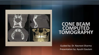
  • 1. CONE BEAM COMPUTED TOMOGRAPHY Guided by: Dr. Navneet Sharma Presentation by: Ayushi Gautam
  • 3. Introduction • Cone beam computed tomography, also known as CBCT, was originally developed for angiography in the early 1980s. • The first dental and maxillofacial units were commercially introduced in the late 1990s and early 2000s. • Unlike other extraoral dental imaging procedures, like panoramic and cephalometric radiography, CBCT acquires data volumetrically providing three-dimensional (3D) radiographic imaging for the assessment of the dental and maxillofacial complex facilitating dental diagnosis. • The role of maxillofacial CBCT has also expanded to image guidance of operative and surgical procedures and also in additive manufacturing of biomodels and surgical guides. • There are three processes in CBCT imaging: image production, visualization and interpretation.
  • 4. Principles of CBCT • In all CT techniques, a collimated x ray source and a detector revolve around the patient. • The detector records photon attenuation by measuring the number of photons that exit the patient and registers this information at several hundred angles through the rotational arc. • These recordings constitute the “raw data” which is then reconstructed by the computer to form a 3D data set through which the image is derived. • The basic component of the resultant greyscale is called Pixel. • Intensity of each pixel is related to the intensity of the photons incident on the detector.
  • 5. • CBCT imaging is performed using a rotating gantry or C-arm supporting the x-ray source and reciprocating the area detector. • A divergent x ray source, collimated as cone or a pyramid, is directed through the region of interest and the residual photons strike the detector on the opposite side. • On activation, data are acquired from a series of sequential exposures as the gantry rotates around a fixed axis of rotation within the patient's ROI. • The arc of the trajectory is ideally 360 degrees and can vary from 180 to 720 degrees. • The resultant raw data is also known as basis, frame, or raw images
  • 6. • The basis images appear in a complete series that is known as projection data. • Because CBCT exposure incorporates the entire ROI, only one rotational scan of the gantry is necessary to acquire enough data for volumetric image construction with the help of various software programs. • These software programs then form volumetric data set which is an image volume that can be used to generate secondary reconstruction images in three orthogonal planes (axial, sagittal, and coronal).
  • 7.
  • 8. Components of image production Three major components: - X-ray generation - X-ray detection - Image reconstruction
  • 9. • Maxillofacial CBCT systems can be distinguished operationally according to the orientation of the patient during image acquisition. Seated According to function, CBCT devices can also be categorized according to functionality and considered a dedicated unit (A and D) or a hybrid unit with panoramic (B) or panoramic and cephalometric capability (C). Standing Supine
  • 10. X ray Generation • CBCT imaging is technically simple as only a single scan of the patient is made to acquire a projection data set. • Numerous other clinically important parameters affect both image quality and patient radiation dose in X-ray generation.
  • 11. Patient Stabilization • CBCT examinations are made with the patient sitting, standing, or supine based on the type of unit. • Supine units are physically larger, have a greater physical footprint so they may not be accessible for patients with some physical disabilities. • On the other hand, standing units may not be able to be adjusted to a height low enough to accommodate wheelchair-bound patients. • Hence, seated units are the most comfortable. • Immobilization of the patient's head is more important than patient positioning because any head movement degrades the final image. Immobilization of the head is achieved by using some combination of a chin cup, bite fork, or other head restraint mechanism.
  • 12. X-Ray Generator • X-ray generation may be continuous or pulsed to coincide with the detector activation (preferably pulsed). • X ray production being pulsed means that actual exposure time can be substantially less than scanning time. • This considerably reduces patient radiation dose. • The ALARA (As Low As Reasonably Achievable) principle of dose optimization necessitates that CBCT exposure factors should be adjusted on the basis of patient size and specific diagnostic task. • This is done by appropriate selection of tube current (milliamperes [mA]), tube voltage (kilovolt peak [kVp]), or both. • In some cases, exposure time also can be adjusted to change scan time.
  • 13. Scan volume • Scan volume primarily depend on the detector size and shape, the beam projection geometry, and the ability to collimate the beam. • The shape of the scan volume can be either cylindrical or spherical. • Collimating the primary x-ray beam limits radiation exposure to the ROI. • It reduces unnecessary exposure to the patient and produces the best images by minimizing scattered radiation, which degrades image quality.
  • 14. Classification of CBCT units according to Field of view (FOV) (A) Large FOV scans provide images of the entire craniofacial skeleton, enabling cephalometric analysis. (B) Medium FOV scans image the maxilla or mandible or both. (C) Focused or restricted FOV scans provide high-resolution images of limited regions. (D) Stitched scans from multiple focused FOV scans provide larger regions of interest to be imaged from superimposition of multiple scans.
  • 15. • Two approaches have been introduced to enable scanning of an ROI greater than the FOV of the detector. 1. One method involves obtaining data from two or more separate scans and superimposing the overlapping regions of the CBCT data volumes using corresponding fiducial reference landmarks that is known as either “bioimage registration” or “mosaicing”. Software is used to fuse adjacent image volumes (“stitching” or “blending”) to create a larger volumetric data set either in the horizontal or in the vertical dimension, the only disadvantage of stitching overlapped regions is that such overlapped regions are imaged twice so the radiation dose is more in these areas.
  • 16. • Increasing Field of View (FOV) by “Stitching” Volumetric Data Sets. Units may use this technique to increase either the vertical (A) or the horizontal (B) FOV. Shown here are adjacent (orange and blue) volumetric data sets
  • 17. • A second method to increase the height or width of the FOV using a small area detector is to offset the position of the detector, collimate the beam asymmetrically, and scan only half the patient's ROI in each of the two offset scans. (A) Conventional geometric arrangement whereby the central ray of the x-ray beam from the focal source is directed through the middle of the object to the center of the FPD. The resultant image is limited to the region of the detector (dentition in this case). (B) Alternative method increasing image size involves shifting the location of the flat panel imager and collimating the x-ray beam laterally to extend the FOV object.
  • 18. Scan Factors • The number of images that constitute the projection data from the scan is determined by the detector frame rate (i.e., the number of images acquired per second),the completeness of the trajectory arc (180 to 360 degrees), and the rotation speed of the source and detector. • Higher frame rates increase the signal-to noise ratio, producing images with less noise and reducing metallic artifacts but takes longer scan time and more exposure time for the patient. • Most CBCT units have fixed scan arcs. Fixed rotation angle units may be a full 360 degrees or partial trajectory arcs. • It is desirable to reduce CBCT scan times to as short as possible to reduce motion artifact resulting from patient movement.
  • 19. Image Detectors • Current CBCT units can be divided into two groups based on detector type: (1) image intensifier tube/charge-coupled device (II/CCD) combination or (2) flat panel detectors (FPDs). • II/CCD units are usually larger and bulkier and result in circular basis image areas (spherical volumes) rather than rectangular ones (cylindrical volumes) produced by FPDs. • FPDs employ an “indirect” detector based on a large area solid-state detector panel coupled to an x-ray scintillator layer. • More recently, large complementary metal oxide semiconductor technology arrays have also been used.
  • 20. Voxel Size • The spatial resolution (details of the CBCT image) is determined by the dimensions of individual voxels produced in formatting the volumetric data set. • CBCT units in general provide voxel resolutions that are isotropic which means equal in all three dimensions. • The principal determinants of nominal voxel size in a CBCT image are the matrix and pixel size of the detector. • Both the focal spot size and the geometric configuration of the x-ray source are important to determine the degree of geometric unsharpness, a limiting factor in spatial resolution.
  • 21. • In maxillofacial CBCT imaging, the detector position is limited because it must be located far enough from the patient's head so that it freely rotates unobstructed by the patient's shoulders. • Limitations also exist in extending the source-to-object distance because this increases the size of the CBCT unit. • Reducing source-to-object distance produces a magnified projected image on the detector, increasing potential spatial resolution.
  • 22. Grayscale • The ability of CBCT imaging to display differences in photon attenuation is related to the ability of the detector to reveal subtle contrast differences. • n is related to the ability of the detector to reveal subtle contrast differences. This parameter is called the bit depth of the system. • All currently available CBCT units use detectors capable of recording grayscale differences of 12 bits or greater.
  • 23. Reconstruction • Although a single acquisition rotation may take less than 20 seconds, it produces 100 to more than 600 individual projection frames, each with more than 1 million pixels with 12 to 16 bits of data assigned to each pixel. • These data are processed to create a volumetric data set composed of cuboidal volume elements (voxels) by a sequence of software algorithms in a process called primary reconstruction. • Subsequently, visual orthogonal (i.e., perpendicular) images are reformatted by sectioning the volumetric data set, referred to as secondary reconstruction. • The reconstruction of these data is computationally complex. To facilitate data handling, data may be acquired by one computer (acquisition computer) and transferred by an Ethernet connection to a processing computer (workstation).
  • 24. • The reconstruction process consists of two stages, each comprising numerous steps Image Acquisition and Reconstruction. The acquisition stage involves acquisition of individual basis projections and subsequent modification of these images to correct for inconsistencies. Image correction is sequential and consists of the removal of signal voids from individual or linear pixel defects, image normalization by histogram equalization so that a full range of voxel intensity values are used, and removal of inherent electronic detector artifacts. After correction, images undergo reconstruction, which includes converting the corrected basis projection images into sinograms and application of the Feldkamp reconstruction to the corrected filters to the image and use of back-projection techniques to reconstitute the image.
  • 25. • 1. Preprocessing stage: The preprocessing stage is performed at the acquisition computer. After the multiple planar projection images are acquired, these images must be corrected for inherent pixel imperfections, variations in sensitivity across the detector, and uneven exposure. • 2. Reconstruction stage: The remaining data-processing steps are performed on the reconstruction computer. The corrected images are converted into a special representation called a sinogram, a composite image developed from multiple projection images. This process of generating a sinogram is referred to as the Radon transformation. The final image is reconstructed from the sinogram with a filtered back projection algorithm for volumetric data acquired by CBCT imaging; the most widely used algorithm is the Feldkamp algorithm. This process is referred to as inverse Radon transformation. When all slices have been reconstructed, they are combined into a single volume for visualization.
  • 26. Cone Beam Computed Tomography (CBCT) Detector Preprocessing. The first step of CBCT detector preprocessing is offset correction. This is accomplished by pixel-wise subtraction of an individual offset value computed by averaging over a series of up to 30 dark images. The second step is the linear gain calibration, consisting of dividing each pixel by its individual gain factor. The gain factors are obtained by averaging a sequence with up to 30 images of homogeneous exposures without any object between x-ray source and detector. The gain sequence is first offset corrected with its own sequence of dark images. The next procedure is the defect interpolation. Each pixel that shows unusual behavior, either in the gain image or in the average dark sequence, is marked in a defect map. The gray values of pixels classified as defective in this way are computed by linear interpolation along the least gradient descent. For flat panel detectors, there is usually an additional procedure to correct for temporal artifacts. These arise in such detectors because both the scintillator and the photodiodes exhibit residual signals.
  • 27. • Reconstruction times vary depending on the acquisition parameters, hardware and software used. • Reconstruction should be accomplished in an acceptable time to facilitate workflow. (<5 minutes)
  • 28. Clinical considerations • Patient Selection Criteria: The principal tenet of the ALARA principle must be applied: There should be justification of the exposure to the patient so that the total potential diagnostic benefits are greater than the individual detriment radiation exposure might cause. A CBCT image should be used only when a lower dose examination, such as a periapical or panoramic view, cannot provide the necessary information for patient diagnosis and treatment. CBCT imaging should be used as an adjunctive diagnostic tool to existing dental imaging techniques for specific clinical applications, not as a screening procedure.
  • 29. • Patient Preparation: Patients should be escorted into the scanner unit and provided with appropriate personal radiation barrier protection before head stabilization. It is recommended that at least a leaded torso apron be applied correctly (above the collar) to the patient. Immediately before the scan, the patient should be asked to remove all metallic objects from the head and neck areas, including eyeglasses, jewelry (including earrings and piercings), and metallic partial dentures. Image quality is severely degraded by head movement, so it is important to obtain patient compliance.
  • 30. • Imaging Protocol: An imaging protocol is a set of technical exposure parameters for CBCT imaging that depend on the specified purpose of the examination. An imaging protocol is developed to produce images of optimal quality with the least amount of radiation exposure to the patient. Operators should be aware of the effects of all parameters on image quality and patient dose when choosing imaging protocols. Icons in light green show the selected settings for a medium field of view (80 mm × 80 mm) with a rotation trajectory of 360-degrees, and a standard nominal resolution. The selected exposure factors (90 kV, 4 mA) can be adjusted to optimize for patient size. The scan time and the radiation dose (computed tomography dose index, CTDI) for these settings are displayed in the top left corner.
  • 31. • Exposure Settings: The quality and quantity of the x-ray beam depend on tube voltage (kVp) and tube current (mA). Some CBCT manufacturers provide units with fixed, nonadjustable exposure settings, whereas others incorporate “preset” exposure settings. A recent CBCT innovation is incorporation of automatic exposure control (AEC) as a dose reduction strategy to optimize patient doses. When exposure reduction is necessary to compensate for differences in patient size, mA changes are preferable to kVp changes as the increase in noise for a given dose reduction is smaller for the former. mA adjustments affect effective dose proportionately. Exposure parameters should be appropriate for both the given patient size and the diagnostic task that motivated image selection.
  • 32.
  • 33. Spatial Resolution: Spatial resolution refers to the ability of an image to reveal fine detail. It is determined primarily by detector nominal pixel size, beam projection geometry, patient scatter, detector motion blur, fill factor), focal spot size, number of basis images, and reconstruction algorithm. Scan Time and Number of Projections: Adjusting the detector frame rate to increase the number of basis image projections results in reconstructed images with fewer artifacts and better image quality but increasing the number of projections requires longer primary reconstruction times and increases patient radiation exposure proportionately.
  • 34. Pictorial Plot of the Effect of Number of Basis Projection Images and Size of Field of View (FOV) on Image Quality. Increasing number of projections in one 360- degree scan (x-axis) provides more data and reduces image noise; however, it increases patient dose proportionately. Reducing the number of projections creates undersampling and produces streaks. Minimizing the FOV (y-axis) reduces patient exposure and resultant scatter radiation and results in images with increased contrast and decreased noise.
  • 35. Scanning Trajectory: Reconstructed images from incomplete, limited, or truncated scanning trajectories of less than 360 degrees may have limited-angle artifacts because of missing information. Field of View: Collimation of the CBCT primary x-ray beam by adjustment of the FOV enables limitation of the x-radiation to the ROI. Reduction of the FOV to the ROI improves image quality because of reduced scattered radiation.
  • 36. Image Artifacts An artifact is any distortion or error in the image that is unrelated to the subject being studied. Artifacts can be classified according to their etiology: • Inherent Artifacts: Artifacts can arise from limitations in the physical processes involved in the acquisition of CBCT data. The beam projection geometry of CBCT, reduced trajectory rotational arcs, and image reconstruction methods produce the following three types of artifacts: a) Scatter b) Partial volume averaging c) Cone beam effect
  • 37. • Scatter results from x-ray photons that are diffracted from their original path after interaction with matter. Scatter causes streak artifacts similar to artifacts of beam hardening. • Partial volume averaging is a feature of both MDCT and CBCT imaging. It occurs when the selected voxel size of the scan is larger than the size of the object being imaged. • The cone beam effect is a potential source of artifacts, especially in the peripheral portions of the scan volume. Because of the divergence of the x-ray beam as it rotates around the patient in a horizontal plane, structures at the top or bottom of the image field are exposed only when the x-ray source is on the opposite side of the patient. The result is image distortion, streaking artifacts, and greater peripheral noise. This picture shows marked graininess or quantum noise caused by contamination of detector signal by scatter radiation.
  • 38.
  • 39. • Procedure-Related Artifacts: Undersampling of the object can occur when too few basis projections are provided for image reconstruction or when rotational trajectory arcs are incomplete. A reduced data sample leads to misregistration, sharp edges, and noisier images as a result of aliasing, which appear as fine striations in the image. Typically, scanner-related artifacts appear as circular or ring streaks resulting from imperfections in scanner detection or poor calibration.
  • 40. • Introduced Artifacts: As an x-ray beam passes through an object, lower energy photons are absorbed in preference to higher energy photons. This phenomenon is called beam hardening. This results in two types of artifact: (1) distortion of metallic structures as a result of differential absorption, known as a cupping artifact. (2) streaks and dark bands, which, when present between two dense objects, create extinction or missing value artifacts
  • 41. • Patient Motion Artifacts: Patient motion can cause misregistration of data, which appear as double contours in the reconstructed image. This problem can be minimized by restraining the head and using as short a scan time as possible. Motion Artifacts. Patient motion during the scanning exposure can result in misregistration artifacts, which appear as double contours in the reconstructed image as demonstrated in the axial (A), coronal (B), and sagittal (C) planes.
  • 42. Strengths and Limitations Strengths: • Size and Cost • Fast Acquisition • Submillimeter Resolution • Relatively Low Patient Radiation Dose • Interactive Analysis
  • 43. Limitations: • Image Noise • Poor Soft Tissue Contrast
  • 45. Introduction • Cone beam computed tomographic (CBCT) imaging is an inherently volumetric image-capture technology providing a data set from which digital images are reformatted and presented on a display monitor. Visualization of CBCT data therefore necessitates that clinicians are familiar with software-assisted volumetric review. • This part focuses on the interaction and use of the subsequent volumetric data for image interpretation, and task-specific applications.
  • 46. Stages in Volumetric Data Display • Most software programs display the CBCT volumetric data set as secondary two-dimensional (2D) contiguous reconstructed images in three orthogonal planes (axial, sagittal, and coronal) at a default thickness. • CBCT data should be considered as a volume that must be analyzed in its entirety, and from which selected images are extracted to document the findings. • Four stages provide an efficient and consistent systematic methodologic approach to optimize CBCT image display before image interpretation: 1. Reorient data 2. Correct data 3. Explore data 4. Format data
  • 47. Reorient data • One of the advantages of CBCT acquisition is that the resultant volumetric data set can be reoriented in relation to three orthogonal planes using imaging software. • The entire volume can be reoriented such that the patient's anatomic features are aligned to fixed orthogonal coordinates. • This stage is particularly important for aligning subsequent cross-sectional, trans axial images perpendicular to the structure of interest. • It helps to visualize single tooth pathology, to measure the maximal height and width of the residual alveolar ridge, to compare temporomandibular joint (TMJ) condylar morphology, or to perform a craniofacial analysis.
  • 48.
  • 49.
  • 50. • Optimize Displayed Images The overall density and contrast of orthogonal images varies between CBCT units and within the same unit depending on the patient size, degree of edentulism, and scan parameters selected. Hence, to optimize image presentation and facilitate diagnosis, it is often necessary to adjust contrast (window width) and brightness (window level) parameters to favor bony structures. After this, secondary algorithms (e.g., annotation, measurement, magnification) can be applied with confidence.
  • 51. Effect of Image Enhancement on Cone Beam Computed Tomographic Images. The visual effect of three sequential adjustments on a multiplanar reformation cross-sectional image. (A) Default image after interpolation algorithm—smoothens edges of cortical bone but adds blur to high- contrast structures. (B) Adjustment of window level and width to bone preset (W/L: 3000/500). (C) Addition of mild sharpen algorithm.
  • 52. Explore data • It is impractical to display all slices on one display format because there are numerous contiguous orthogonal images in each plane. • Therefore each series must be reviewed dynamically by scrolling through the consecutive orthogonal image “stack.” • This is referred to as navigating through the volume in a “cine” or “paging” mode. • Scrolling is performed craniocaudally, and the in reverse direction slowing down in complex areas and is done in two planes.
  • 53. Format Data • All CBCT software, be it either proprietary acquisition and display original equipment manufacturer (OEM) or commercial third-party display programs, are capable of many formatting options. • Each of these is directed toward visualizing specific components of the volumetric data set. • There are two basic format options: • Multiplanar reformation • Volumetric rendering
  • 54. Display Mode Options of Cone Beam Computed Tomographic Volumetric Data. Display modes can be divided into two categories: multiplanar reformation (MPR) consisting of linear, curved oblique, and serial trans axial images; and volumetric images including ray sum, comprising images of increased section thickness, indirect volume rendering (IVR), the most common of which being maximum intensity projection (MIP), and direct volume rendering (DVR).
  • 55. Multiplanar reformation: • Because of the isotropic nature of acquisition, the volumetric data set can be sectioned nonorthogonally to provide 2D planar images referred to as multiplanar reformation (MPR). • MPR modes include linear oblique, curved planar, and serial trans axial reformations. • Linear oblique images are most often used to transect the mandibular condyle. Curved planar images are generated by manually drawing a planning line or spline by selecting multiple nodes along the centerline. • Serial sequential images perpendicular to an arbitrary linear oblique or curved planar MPR provide a dynamic representation of the anatomic structure, minimizing parallax error. These images are referred to as trans axial, tangential or, most commonly, cross-sectional images. • Cross sectional images have two characteristics, a slice thickness and distance between adjacent cross-sectional images (interslice interval).
  • 56. Multiplanar Reformation (MPR). A thick axial image (A) simulating an occlusal image with an MPR oblique curved line (white solid line) and resultant “panoramic” image (B) and serial cross-sectional, 1-mm-thick images (C) of a potential implant site in the lower left mandible. The axial and panoramic images are used as reference images to show the location of the cross-sectional images. The cross-sectional images demonstrate the amount of lingual undercut and location of the inferior alveolar canal.
  • 57. Volume Rendering • Volume rendering allows visualization of volumetric data by selective display of voxels within a data set as a 2D projection. • Two specific techniques are commonly used: indirect volume rendering (IVR) and direct volume rendering (DVR).  Indirect volume rendering: It is a complex process requiring selection of the intensity or density of the grayscale level of the voxels to be displayed within an entire data set known as segmentation. This process is technically demanding and computationally difficult, requiring specific software. Two types of views are possible: views that are solid (surface rendering) and views that are transparent (volumetric rendering).
  • 58. Three-Dimensional Volumetric Surface Rendering. Manual segmentation is often accomplished by an adjustable scale determining the upper and lower limit and range of intensity values to include in the segmentation. The visual result of changes in this scale is displayed in “real time” so that the effects of incremental changes can be visualized. The segmentation may be optimized to reveal the objects of interest, including bone as a solid surface or shaded surface display (A) and bone and the dentition under the bone as a transparency (B) using volumetric imaging.
  • 59.  Direct volume rendering: It is a much simpler process that involves selecting an arbitrary threshold of voxel intensities, below or above which all gray values are removed. The most commonly used techniques are ray sum and maximum intensity projection (MIP). The slice thickness of orthogonal or MPR images can be “thickened” by increasing the number of adjacent voxels included in the display that creates an image slab that represents a specific volume of the patient, referred to as a ray sum. In contrast to conventional radiographs, these ray sum images are without magnification and parallax distortion. But, this technique uses the entire volumetric data set, and interpretation is negatively affected by “anatomic noise”—the superimposition of multiple structures—also present in conventional projection radiography.
  • 60. Ray Sum Images. (A) An axial projection is used as the reference image. A section slice is identified that in this case corresponds to the midsagittal plane, and the thickness of this slice is increased to include both left and right sides of the volumetric data set. As the thickness of the “slab” increases, adjacent voxels representing elements such as air, bone, and soft tissues are added. (B) The resultant image generated from a full-thickness ray sum provides a simulated lateral cephalometric image.
  • 61. Two-Dimensional Projections Generated With Cone Beam Data Set. This patient had an asymmetry of one side of the face. Ray sum reformation of the cone beam computed tomographic data was performed to provide multiple conventional images, such as the lateral cephalometric (A), frontal cephalometric or posteroanterior (B), and panoramic (C) projections
  • 62. • Maximum intensity projection (MIP) visualizations are achieved by evaluating each voxel value along an imaginary projection ray from the observer's eyes within a particular volume of interest and representing only the highest value as the display value. Voxel intensities that are below an arbitrary threshold are eliminated MIP images have great utility for demonstration of the location of impacted teeth, for TMJ evaluation, for identification of fractures, for craniofacial analysis, for surgical follow-up, for assessment of cervical spine anomalies, and for demonstration of soft tissue dystrophic calcifications.
  • 63. In this example, an axial projection (A) is used as the reference image. A projection ray is identified throughout the entire volumetric data set along which individual voxels are identified, each with varying grayscale intensity corresponding to various tissue densities, such as fat, muscle, air, and bone. The MIP algorithm selects only the values along the projection ray that have the highest values (usually corresponding to bone or metal) and represents this as only one pixel on the resultant image (B).
  • 64. Interpretive Report • Documentation of the CBCT procedure by the inclusion of an interpretive report is an essential element of CBCT imaging and should form part of a patient's record. • Patient diagnosis may often be complex, and management may involve numerous practitioners. • An interpretation report serves as the optimal method of communication of interpretation findings for CBCT.
  • 65.
  • 66. Task-Specific Applications • Diagnosis and Preoperative Assessment:  Implant Site Assessment : Perhaps the greatest impact of CBCT has been on the planning of dental implant placements. The most useful series of images for implant site assessment include the axial, reformatted panoramic, and cross-sectional images at the specific location. Cone Beam Computed Tomographic Imaging for Implant Site Assessment. A curved planar multiplanar reformation (MPR) is accomplished by aligning the long axis of the imaging plane with the dental arch (A), providing a regional panorama-like thin-slice image (B). In addition, serial thin-slice trans axial images are often generated perpendicular to the curved planar MPR (C), which are useful in the assessment of specific morphologic features, such as the location of the inferior alveolar canal (shown with a white dot) for implant site assessment and for allowing measurement of the available alveolar bone height and width (solid line)
  • 67. Use of a Radiographic Template. Plastic intraoral appliances provide fiducial radiographic landmarks that can be used to correlate proposed clinical location and angulation of implants with the available alveolar bone. The axial (A) and panoramic (B) projections provide an overview of location, whereas serial cross-sectional images (C) indicate alveolar bone height. In this example of an edentulous mandible, the radiograph has two markers at proposed implant sites; the 1-mm-thick trans planar images at 3-mm intervals of the mandibular anterior region (C) indicate that although the right trajectory is optimal (upper left cross-sectional image), the proposed placement trajectory of the right implant (lower left) is too far buccal to engage the available bone.
  • 68.  Endodontics: The use of CBCT imaging in endodontics is indicated in the following clinical situations- • Patients who present with contradictory or nonspecific clinical signs and symptoms associated with untreated or previously endodontically treated teeth. • For the initial treatment of teeth with the potential for extra canals and suspected complex morphology, such as mandibular anterior teeth, and maxillary and mandibular premolars and molars, and dental anomalies. • For intra-appointment identification and localization of calcified canals. • If clinical examination and 2D intraoral radiography are inconclusive in the detection of vertical root fracture. • When evaluating the non-healing of previous endodontic treatment to help determine the need for further treatment, such as nonsurgical, surgical, or extraction.
  • 69. • For nonsurgical retreatment to assess endodontic treatment complications, such as overextended root canal obturation material, separated endodontic instruments, and localization of perforations. • For presurgical treatment planning to localize root apex/apices and to evaluate the proximity to adjacent anatomical structures. • For the surgical placement of implants. • For diagnosis and management of limited dentoalveolar trauma, root fractures, luxation, and/or displacement of teeth, and localized alveolar fractures, in the absence of other maxillofacial or soft tissue injury that may require other advanced imaging modalities. • For the localization and differentiation of external and internal resorptive defects and the determination of appropriate treatment and prognosis.
  • 70. Cone Beam Computed Tomographic (CBCT) Imaging for Endodontics. Numerous endodontically related conditions can be demonstrated in high resolution with restricted field of view CBCT imaging, including periapical conditions (A); periodontal, periapical, and sinus disease (B); and root fracture and associated alveolar bone loss (C).
  • 71.  Orthodontics and Three-Dimensional Cephalometry: CBCT imaging is used in the diagnosis, assessment, and analysis of maxillofacial orthodontic and orthopedic anomalies. CBCT imaging facilitates surgical exposure and planning of subsequent movement. Other applications include the assessment of palatal morphologic features and dimensions, tooth inclination and torque, characterization of alveolar bone for orthodontic mini-implant placement, and determining available alveolar bone width for buccolingual movement of teeth. CBCT imaging also provides adequate visualization of the TMJ, pharyngeal airway space, and soft tissue relationships.
  • 72. • CBCT imaging provides two unique contributions to orthodontic practice: i. Numerous linear images currently used in orthodontic diagnosis, cephalometric analysis, and treatment planning can be created from a single CBCT scan. This capability provides for greater clinical efficacy. ii. CBCT data can be reconstructed to provide unique, previously unavailable images. The numerous potential benefits to 3D cephalometry include demonstrating and characterizing asymmetry and anteroposterior, vertical, and transverse dentoskeletal discrepancies, incorporating the soft tissue integument, and the potential for assessment of growth and development.
  • 73.  Mandibular Third Molar Position: The relationship of the IAC to the roots of mandibular third molar teeth is important when considering extractions and attempting to minimize the likelihood of nerve damage that may lead to permanent loss of sensation to one side to the lower lip. Accurate assessment of the position of the IAC in relation to the impacted third molar may reduce injuries to this nerve.
  • 74. Cone Beam Imaging for Third Molar Assessment. Third-party software used to demonstrate the location of the inferior alveolar canal (IAC) (green). Nonannotated (A) and annotated (B) panoramic multiplanar reformation reformatted, volumetric transparency reconstruction (C) images with corresponding nonannotated (D) and annotated field of view (E) cross-sectional images at 1-mm intervals. Crosssectional slices with the IAC traced (green). All images demonstrate the close proximity and course of the IAC in relation to the root of the left mandibular, horizontally bony impacted and unerupted third molar.
  • 75.  Temporomandibular Joint: CBCT imaging provides multiplanar and potentially 3D images of the condyle and surrounding structures to facilitate analysis and diagnosis of osseous morphologic features and joint space and function. Imaging can depict the features of degenerative joint disease and developmental anomalies of the condyle, ankylosis, and rheumatoid arthritis.
  • 76. Cone Beam Computed Tomographic Imaging of the Temporomandibular Joint (TMJ). Corrected coronal (A) and sagittal (B) images of a right TMJ with erosive defects on the superior cortical surface of the condyle associated with mild degenerative joint disease.
  • 77.  Maxillofacial Pathoses: CBCT imaging can assist in the assessment of many conditions of the jaws, most notably dental conditions such as impacted canines and supernumerary teeth, fractured or split teeth, periapical lesions, and periodontal disease. Benign calcifications (e.g., tonsilloliths, lymph nodes, salivary gland stones) can also be identified by location. Although CBCT imaging does not provide suitable soft tissue contrast to distinguish the contents of paranasal soft tissue attenuations, the morphologic characteristics and extent of these lesions are particularly well seen (e.g., mucous extravasation cyst). CBCT imaging is particularly useful for assessment of trauma and for visualizing the extent and degree of involvement of benign odontogenic or nonodontogenic cysts and tumors as well as osteomyelitis.
  • 78. Cone Beam Computed Tomographic Imaging of Mandibular Fractures. Use of maximum intensity projection (MIP) in the assessment of complex mandibular fractures. (A) Oblique thin slab multiplanar reformation image with MIP application demonstrates a simple, slightly displaced fracture of the right parasymphyseal region. (B) Coronal thin-slab MIP image demonstrates a comminuted displaced left subcondylar neck fracture. Cone Beam Computed Tomographic Imaging of Maxillofacial Pathology. (A) Cropped reformatted ray sum panoramic view. (B) Axial slice at level of red horizontal line on panoramic view and outline for midportion of cross-sectional images. (C) Serial 1- mm-thick cross-sectional slices (of unilocular well-defined hypodensity) in the left premolar mandibular body of a patient in the mixed dentition phase.
  • 79. Treatment Planning and Virtual Simulations • The key feature of CBCT image output that makes systems interoperable is the use of image files that are conformant with the Digital Imaging and Communications in Medicine (DICOM) standard file format. • Treatment planning for a potential implant site involves an interplay of considerations of both surgical and prosthetic requirements. • In implant planning, software can be used to select and direct the placement of implant fixtures either directly by the use of image-guided navigation or indirectly via the construction of restrictive surgical guides.
  • 80. Virtual Simulation Planning for Implant Placement. (A) Reformatted thin section panoramic of a partially dentate maxilla shows the alignment of the two virtual implant bodies (yellow outline) in relation to the radiographic markers providing the planned occlusal surface of the right first premolar and left second premolar teeth. (B) Axial image showing the buccopalatal position of the right implant (yellow outline) in the residual alveolar ridge. (D) Composite cone beam computed tomographic and optical intraoral surface scan of the teeth and mucosa (silver) shows the buccopalatal emergence profile (yellow solid line) and position (implant outline in solid yellow). Software also allows the use of overlay prosthetic tools, such as (1) surgical confidence marker (dark blue outline around each implant used to identify 0.5-mm surgical tolerance limits); (2) tapering drill confidence limit, shown on the apical portion of the implant (space between yellow implant and blue outline, C); and (3) soft tissue collar (white outline, C).
  • 81. • Image fusion is the process of integration of two imaging data sets. Most commonly, CBCT volumes are fused with extraoral facial (photographic) or intraoral (impression) optical data. After registration, numerous options allow interaction with the data sets either independently or in toto. Fusion Image. Right lateral (A), 45-degree (B), and frontal (C) three-dimensional (3D) anatomic views demonstrate image fusion possibilities. (A) Volumetric cone beam computed tomographic (CBCT) rendering. (B) CBCT data fused with high- resolution intraoral optical surface scanning of the teeth. (C) CBCT intraoral optical scan and facial digital photographs fused to form a composite 3D image set.
  • 82. Image-Guided Surgery and Additive Manufacturing • Imaged-guided surgery refers to techniques that translate software-derived virtual surgical plans developed from virtual simulations to the surgical environment. • Two concepts for image-guided surgery have been developed: a. The first concept involves the fabrication of a plastic drilling or surgical template based on a virtual treatment plan. b. The second concept incorporates expensive navigation systems that implement the techniques of frameless stereotaxy. This real-time, in operatory, display-driven virtual guidance of surgical tools is based on the registration of the surgical instrument with the virtual patient as demonstrated by CBCT data
  • 83. • Additive manufacturing (AM) is a broad term to describe a group of related processes and techniques used to fabricate physical scale models directly from 3D computer-assisted design data. • 3D printing is but one of a range of AM processes in which material is extruded through fine nozzles in layers to create an object—similar to inkjet printer print heads. • In maxillofacial imaging, the most obvious and widespread clinical application of the use of AM has been in the fabrication of surgical guides to assist in dental implant placement. • However, biomodels, customized plastic dimensionally accurate anatomic models of the maxillofacial skeleton, can also be fabricated.
  • 84. Additive Manufacturing for Orthognathic Surgery. (A) Three-dimensional volumetric reconstruction of the maxilla and mandible after virtual surgery combining maxillofacial cone beam computed tomographic data and optical surface scans of the dentition. Note the wafer separating the maxillary and mandibular dentition that is used as a surgical guide to confirm the final relationship of the dentition. (B) Biomodel of the maxillofacial complex after virtual surgery with interposed plastic surgical stent. Modeling was performed to provide a physical model with which to confirm the actual surgery and fit of the surgical guide.
  • 85. Additive Manufacturing In-Office Printing. (A) Example of in-office threedimensional resin based printer (NP1, NewPro3D, Burnaby, BC, Canada) using a proprietary modification of digital light processing technology (ILI Technology). (B) Schematic showing ILI technology. An accurate resin object (formed object), such as a biomodel or surgical guide, is created by projection of a light pattern (light projector) onto a wettable membrane between the photo-curing resin (liquid resin) and the light source. The object is created by sequential layering of photo-polymerized resin with upward translation of the build platform.
  • 86. Conclusion • CBCT technology has expanded maxillofacial CBCT imaging from diagnosis and image guidance of operative and surgical procedures into 3D printing. • The use of CBCT has allowed greater predictability in the diagnosis and subsequent care of patients, especially those with complex conditions. • This imaging tool brings with it an increased practitioner responsibility in the performance, optimal visualization, and interpretation of volumetric data sets.
  • 87. References: o White and Pharoah's Oral Radiology Principles and Interpretation 8TH EDITION

Editor's Notes

  1. Cone Beam Imaging Geometry. A divergent x-ray beam created at the tube head is collimated in a circle or rectangle (this example) into a three-dimensional cone or pyramid, respectively. The x-ray projection is directed through the patient onto a detector (either solid-state flat panel detector [this example] or II/charge-coupled device). After a single two-dimensional projection is acquired by the detector, the xray source and detector rotate a small distance around a trajectory arc. At this second angular position, another basis projection image or frame is captured. This sequence continues around the object for the entire 360 degrees (full trajectory) or along a reduced or partial trajectory capturing hundreds of individual images.
  2. A: e.g., 3D Accuitomo 170 B: X-Mind trium Pan 3D C: Rayscan Alpha 3D D: Newtom 5G
  3. During the scan rotation, each projection image set is made by sequential single-image capture of the remnant attenuated x-ray beam by the area detector. The variation in exposure parameters together with the presence of pulsed x-ray beam and size of the image field are the primary determinants of patient exposure.
  4. Detectors with smaller pixels capture fewer x-ray photons per voxel and result in more image noise.
  5. Additional factors influencing image resolution include motion of the patient's head during the exposure, the type of scintillator used in the detector, and the image reconstruction algorithms applied.
  6. A 12-bit detector provides 2 12 or 4096 shades to display contrast. A 16-bit detector provides 2 16 or 65,536 shades of gray.
  7. Cone Beam Computed Tomography (CBCT) Detector Preprocessing. The first step of CBCT detector preprocessing is offset correction. This is accomplished by pixel-wise subtraction of an individual offset value computed by averaging over a series of up to 30 dark images. The second step is the linear gain calibration, consisting of dividing each pixel by its individual gain factor. The gain factors are obtained by averaging a sequence with up to 30 images of homogeneous exposures without any object between x-ray source and detector. The gain sequence is first offset corrected with its own sequence of dark images. The next procedure is the defect interpolation. Each pixel that shows unusual behavior, either in the gain image or in the average dark sequence, is marked in a defect map. The gray values of pixels classified as defective in this way are computed by linear interpolation along the least gradient descent. For flat panel detectors, there is usually an additional procedure to correct for temporal artifacts. These arise in such detectors because both the scintillator and the photodiodes exhibit residual signals.
  8. acquisition parameters (voxel size, size of the image field, and number of projections) , hardware (processing speed, data throughput from acquisition to reconstruction computer) and software (reconstruction algorithms) used.
  9. similar, in many respects, to the performance of panoramic radiography. However, in contrast to panoramic imaging, numerous exposure and acquisition settings may be adjusted, depending on the CBCT unit used CBCT examination be documented by entry in the patient's chart or on the written request or prescriptive order for the CBCT examination.
  10. Use of a leaded apron is particularly advisable for pregnant patients and for children.