SlideShare a Scribd company logo
1 of 1
The packet switch consists of k input buffer controllers, k output buffer controllers, and a k x k square
        switch.

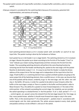
A Banyan network is considered for the switching fabric because of its economy, potential VLSI
        implementation, and easiness of routing.


         Each switching element (box) is a 2 X 2 crossbar switch with one buffer on each of its two
         Input links. The packet routing is done by the hardware as follows:

         Each packet has an n-bit header in an n-stage Switch. The switching element (a 2 X 2 crossbar)
         at stage 1 Routes the packet up or down according to the first bit of The header’ (“zero” or
         “one” indicate up or down routing, Respectively) and then removes the first bit from the
         header. The succeeding switching elements will perform the same Routing function by
         removing one bit from the header and Routing the .packet to the next stage until the packet
         Reaches its destination output l I n k. It is easy to see that the Header is simply the binary
         address of the output link at The last stage and is independent of the input link at the First
         stage. If both buffers a t a switching element have a packet and Both packets are going to the
         same output link of the Switching element, then a conflict occurs. In this case, we Assume that
         one of the packets will be chosen, randomly, to go to the next stage and the other one will
         stay in the Buffer. Of course, in order for a packet to be able to move Forward, either the
         buffer at the next stage is empty or There is a packet in the buffer and that packet is able to
         Move forward. Thus, the ability for a packet to move Forward depends o n’ the state of the
         entire portion of the network succeeding the current stage. For simplicity, we can consider
         the switch operating in a clocked format. In the first portion 71 of a clock period T = T~ + r 2
         , control signals. are passed across the network from the last stage toward the first stage, so
         that every packet knows whether it should move forward one stage or stay in the same
         buffer. Then, in the second portion T~ of a clock period T , packets move in accordance with
         control signals and the clock period ends. The whole process repeats in every clock period,
         and packets continue e to be shifted in and out of the switch.

More Related Content

What's hot

Du binary signalling
Du binary signallingDu binary signalling
Du binary signalling
srkrishna341
 
Data Communication And Networking - DATA RATE LIMITS
Data Communication And Networking - DATA RATE LIMITSData Communication And Networking - DATA RATE LIMITS
Data Communication And Networking - DATA RATE LIMITS
Avijeet Negel
 

What's hot (20)

NYQUIST CRITERION FOR ZERO ISI
NYQUIST CRITERION FOR ZERO ISINYQUIST CRITERION FOR ZERO ISI
NYQUIST CRITERION FOR ZERO ISI
 
Data and signals
Data and signalsData and signals
Data and signals
 
Leaky Bucket & Tocken Bucket - Traffic shaping
Leaky Bucket & Tocken Bucket - Traffic shapingLeaky Bucket & Tocken Bucket - Traffic shaping
Leaky Bucket & Tocken Bucket - Traffic shaping
 
Analog-to Digital Conversion
Analog-to Digital ConversionAnalog-to Digital Conversion
Analog-to Digital Conversion
 
Concept of Diversity & Fading (wireless communication)
Concept of Diversity & Fading (wireless communication)Concept of Diversity & Fading (wireless communication)
Concept of Diversity & Fading (wireless communication)
 
ASk,FSK,PSK
ASk,FSK,PSKASk,FSK,PSK
ASk,FSK,PSK
 
Quadrature amplitude modulation
Quadrature amplitude modulationQuadrature amplitude modulation
Quadrature amplitude modulation
 
Chapter 4 - Digital Transmission
Chapter 4 - Digital TransmissionChapter 4 - Digital Transmission
Chapter 4 - Digital Transmission
 
M ary psk modulation
M ary psk modulationM ary psk modulation
M ary psk modulation
 
Equalization
EqualizationEqualization
Equalization
 
Computer Networks Unit 1 Introduction and Physical Layer
Computer Networks Unit 1 Introduction and Physical Layer Computer Networks Unit 1 Introduction and Physical Layer
Computer Networks Unit 1 Introduction and Physical Layer
 
Computer network switching
Computer network switchingComputer network switching
Computer network switching
 
Du binary signalling
Du binary signallingDu binary signalling
Du binary signalling
 
Csma protocols
Csma protocolsCsma protocols
Csma protocols
 
DRAM Cell - Working and Read and Write Operations
DRAM Cell - Working and Read and Write OperationsDRAM Cell - Working and Read and Write Operations
DRAM Cell - Working and Read and Write Operations
 
Digital modulation techniques...
Digital modulation techniques...Digital modulation techniques...
Digital modulation techniques...
 
Introduction to switching & circuit switching
Introduction to switching & circuit switchingIntroduction to switching & circuit switching
Introduction to switching & circuit switching
 
Pulse Code Modulation (PCM)
Pulse Code Modulation (PCM)Pulse Code Modulation (PCM)
Pulse Code Modulation (PCM)
 
Line codes
Line codesLine codes
Line codes
 
Data Communication And Networking - DATA RATE LIMITS
Data Communication And Networking - DATA RATE LIMITSData Communication And Networking - DATA RATE LIMITS
Data Communication And Networking - DATA RATE LIMITS
 

Viewers also liked (8)

4b internet protocol
4b internet protocol4b internet protocol
4b internet protocol
 
4d routing
4d routing4d routing
4d routing
 
4a logical laddressing
4a logical laddressing4a logical laddressing
4a logical laddressing
 
2b switching in networks
2b switching in networks2b switching in networks
2b switching in networks
 
Chapter 8
Chapter 8Chapter 8
Chapter 8
 
4c Address Mapping, Error Reporting and Multicasting
4c Address Mapping, Error Reporting and Multicasting4c Address Mapping, Error Reporting and Multicasting
4c Address Mapping, Error Reporting and Multicasting
 
circuit switching
circuit  switchingcircuit  switching
circuit switching
 
Switching
SwitchingSwitching
Switching
 

More from Ashu0711 (20)

Project ppt
Project pptProject ppt
Project ppt
 
Pi q
Pi qPi q
Pi q
 
My cad lab file
My cad lab fileMy cad lab file
My cad lab file
 
My cad file
My cad fileMy cad file
My cad file
 
Monolithic&hybrid ic
Monolithic&hybrid icMonolithic&hybrid ic
Monolithic&hybrid ic
 
Mini project-report
Mini project-reportMini project-report
Mini project-report
 
Metallization
MetallizationMetallization
Metallization
 
Anti theftsystemforvechicles1 final
Anti theftsystemforvechicles1 finalAnti theftsystemforvechicles1 final
Anti theftsystemforvechicles1 final
 
4.inverter final
4.inverter final4.inverter final
4.inverter final
 
3. solar water heater
3. solar water heater3. solar water heater
3. solar water heater
 
2.avr final
2.avr final2.avr final
2.avr final
 
ups
upsups
ups
 
Industrial training report format
Industrial training report formatIndustrial training report format
Industrial training report format
 
Quality management concepts
Quality management conceptsQuality management concepts
Quality management concepts
 
Project landrover
Project landroverProject landrover
Project landrover
 
Ppt land rover
Ppt land roverPpt land rover
Ppt land rover
 
Organizational design qm
Organizational design qmOrganizational design qm
Organizational design qm
 
Mini p gsm based display
Mini p gsm based displayMini p gsm based display
Mini p gsm based display
 
Mini p gsm based display
Mini p gsm based displayMini p gsm based display
Mini p gsm based display
 
Manufacturing quality qm
Manufacturing quality qmManufacturing quality qm
Manufacturing quality qm
 

16 x 16 banyan switch

  • 1. The packet switch consists of k input buffer controllers, k output buffer controllers, and a k x k square switch. A Banyan network is considered for the switching fabric because of its economy, potential VLSI implementation, and easiness of routing. Each switching element (box) is a 2 X 2 crossbar switch with one buffer on each of its two Input links. The packet routing is done by the hardware as follows: Each packet has an n-bit header in an n-stage Switch. The switching element (a 2 X 2 crossbar) at stage 1 Routes the packet up or down according to the first bit of The header’ (“zero” or “one” indicate up or down routing, Respectively) and then removes the first bit from the header. The succeeding switching elements will perform the same Routing function by removing one bit from the header and Routing the .packet to the next stage until the packet Reaches its destination output l I n k. It is easy to see that the Header is simply the binary address of the output link at The last stage and is independent of the input link at the First stage. If both buffers a t a switching element have a packet and Both packets are going to the same output link of the Switching element, then a conflict occurs. In this case, we Assume that one of the packets will be chosen, randomly, to go to the next stage and the other one will stay in the Buffer. Of course, in order for a packet to be able to move Forward, either the buffer at the next stage is empty or There is a packet in the buffer and that packet is able to Move forward. Thus, the ability for a packet to move Forward depends o n’ the state of the entire portion of the network succeeding the current stage. For simplicity, we can consider the switch operating in a clocked format. In the first portion 71 of a clock period T = T~ + r 2 , control signals. are passed across the network from the last stage toward the first stage, so that every packet knows whether it should move forward one stage or stay in the same buffer. Then, in the second portion T~ of a clock period T , packets move in accordance with control signals and the clock period ends. The whole process repeats in every clock period, and packets continue e to be shifted in and out of the switch.