Call Girls In Mukherjee Nagar 📱 9999965857 🤩 Delhi 🫦 HOT AND SEXY VVIP 🍎 SE...
computer Unit 3
1. Microcomputers and Microprocessors
53
Unit 3: Microcomputers and
Microprocessors
Introduction
This unit focuses on popular microcomputer systems and
microprocessors. Lesson 1 of this unit presents the architecture and I/0
communications of microcomputer systems. Microprocessor, the brain
of a microcomputer with its functional units, is described in Lesson 2.
This lesson also includes description of arithmetic logic unit and control
unit in detail. Lesson 3 provides the information of popular
microprocessors, namely, CISC, RISC and special purpose of
processors.
Lesson 1: Microcomputer and Organization
1.1 Learning Objectives
On completion of this lesson you will be able to:
• understand structure of a microcomputer
• understand communication techniques between processor and
other devices
• understand telecommunications for distant microcomputer.
1.2 Architecture of a Microcomputer
The most modern microcomputers utilize a motherboard, a single large
circuit board containing the microprocessor unit (MPU), ROM, RAM,
and other associated circuits. These elements are linked through a series
of parallel metal lines etched into the motherboard called the system bus.
The system bus carries three types of information; these are: control,
address, and data. Control information is carried by a number of control
lines, addresses by a number of address lines and data by data lines.
The width of the bus is important to the performance of the computer.
The wider the bus, the more information can be carried at one time and
the greater the throughput of the system. Most 16-bit microcomputers
use 8 or 16-bit buses, 32-bit microcomputers use 8-bit, 16-bit, and 32-bit
buses, while 64-bit microcomputers use 16-bit, 32-bit and 64-bit buses.
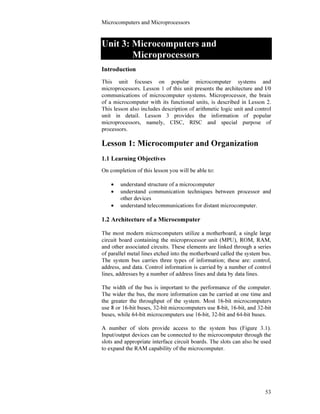
A number of slots provide access to the system bus (Figure 3.1).
Input/output devices can be connected to the microcomputer through the
slots and appropriate interface circuit boards. The slots can also be used
to expand the RAM capability of the microcomputer.
2. Computer Basics
54
I/O Interface
Communications between an input/output device and the MPU take
place through an interface. The interface converts the data from a form
used by one of these devices to a form acceptable by the other. It must
also adjust for speed differences between the processor and the other
device. The interface circuits of microcomputers correspond to the I/O
control units used on larger computer systems.
Two general types of interface devices in use are serial and parallel. A
serial interface transmits data as a string of bits, one bit after the other,
over a single wire. A parallel interface transmits data byte by byte
through a multiwire cable.
Figure 3.1 : Microcomputer architecture.
Parallel interface devices are faster, but are more costly. The interface
must match the requirements of the device it supports.
Serial and parallel interface.
3. Microcomputers and Microprocessors
55
Figure 3.2 illustrates some of the I/O devices generally connected to a
microcomputer. These devices are linked through a common system bus.
Communications between these devices take place over this bus, under
control of the processor. Thus, the bus while carrying data from a disk
device to memory, for example, cannot carry data to or from the
keyboard, monitor, or any other I/O device.
Some microcomputer systems use a separate microprocessor to handle
I/O operations. This frees the MPU to perform non-I/O operations on
other programs while the separate processor handles the I/O operations
for the current program.
Figure 3.2 : Peripheral devices in a microcomputer.
Input/Output Methods
There are three basic methods by which data can be read (or input) from
or written (or output) to a peripheral device and RAM. These methods
are referred to as: programmed I/O, interrupt I/O, and direct memory
access.
In programmed I/O, the MPU directly controls all data transfers and
other I/O operations. This is accomplished with input or output
instructions. When an input operation is desired, the MPU issues an
MPU
ROM
Printer Parallel
Interface
RS-232c
Serial Interface
Keyboard
Parallel
Interface
Video Display
Parallel
Interface
Floppy Disk
Controller
Chip
Expansion
Slots
System bus
Control Lines
Data Lines
Address
Lines
RAM
4. Computer Basics
56
input command and awaits the arrival of the data at the bus. From the
bus the data are moved to memory. Similarly for an output operation, the
MPU transmits the data to the bus and issues a command to the output
device through the appropriate interface. Once data transfer is initiated,
the MPU should wait for its completion and the bus to be freed before
beginning a new transfer. This method is commonly used in personal
computers.
In the interrupt I/O method, the MPU does not wait for the input/output
devices to complete their tasks. The control of the operation is given to a
channel. The channel signals the MPU when the operation has been
completed. This is accomplished by means of an interrupt. Upon
completion of the execution of the current instruction, the MPU may
then initiate another I/O operation.
Direct memory address method is the fastest of the three methods. It
requires a multibus architecture and allows the MPU to be bypassed
completely. A direct memory access controller is connected between
RAM and an input or output device. This method is the most expensive
of the all and therefore is not used except with very high-speed
input/output devices.
Telecommunications Between Microcomputers
Most microcomputers also support the transfer of data through telephone
line. This is facilitated by means of an add-on device known as a
modem. In telecommunications, one computer or terminal issues a
command, or some form of output. This digital output from the
computer, is modulated, or converted to an analog signal, by a modem
interfaced to the sending computer. The signal is then carried over the
telephone line and received at another modem some distance away. This
second modem then demodulates, or converts the analog signal back to a
computer-compatible digital signal. The name modem performs the
functions of modulation and demodulation. Thus, with the aid of a
modem and a serial interface to a microcomputer, communication can
take place over long distances. The speed with which these
communications take place is dependent on the modem employed.
Direct memory address
method
Modem performs the
functions of modulation and
demodulation.
Interrupt I/O method
5. Microcomputers and Microprocessors
57
1.3 Exercise
1. Multiple choice questions
a. Which of the following is the main component of the
microcomputer?
(i) ROM
(ii) Microprocessor
(iii) Motherboard
(iv) Bus system.
b. The fastest method by which data can be input from or output to a
peripheral device and RAM are:
(i) Programmed I/O
(ii) Interrupt I/O
(iii) Direct memory access
(iv) Serial Input/Output.
c. Which are the functions of modem?
(i) Analog to digital conversion
(ii) Modulation and demodulation
(iii) Digital to analog conversion
(iv) None of them.
2. Questions for short answers
a. What is a bus?
b. What is the difference between serial and parallel interfaces?
c. Write down the names of three of basic methods by which data
can be input from or output to a peripheral device and RAM.
3. Analytical question
a. Describe the architecture and I/O interface of a microcomputer.
6. Computer Basics
58
Lesson 2: Basics of Microprocessors
2.1 Learning Objectives
On completion of this lesson you will be able to :
• describe functional units of a microprocessor
• understand working principles of arithmetic logic unit and
control unit
• describe instruction cycle and instruction execution.
2.2 Microprocessor and its Functional Units
The microprocessor is an electronic device. It is the heart and brain
inside every microcomputer. This tiny chip of silicon determines the
speed and power of the entire computer by handling most, if not all, of
the processing jobs in the machine. The microprocessor is composed of
an arithmetic/logic unit and a control unit. Both utilize temporary
storage areas, called registers, to perform their functions. These registers
are: accumulator, instruction register, address register, and other special-
and general-purpose registers. Primary storage is available on separate
integrated circuits but is logically and electronically connected to the
microprocessor. A system of wires linking these internal components
and capable of transmitting electrical impulses is referred to as a bus.
Most microcomputers use one or more internal or local buses for
communicating within the microprocessor and a common or system bus
for communicating with components outside the microprocessor.
Prefetch Unit and Instruction
Queue
Decoding
unit
Data
Bus
Bus Interface
Unit (BIU)
Integer
Register File
(IRF) Branch Target Control
Address
B/us
Data Cache
(Dcache)
Cache (BTC) Unit (CU)
Control
Bus
Memory
Management
Unit (MMU)
Internal Bus
Integer Unit (IU) Floating Point
Unit (FPU)
Special
Function
Integer Register
File (IRF)
Floating Point
Register File
(FRF)
Unit (SFU) Integer
Operation Unit
Floating Point
Operation Unit
Figure 3.3 Block representation of a microprocessor.
Microprocessor is the heart
and brain inside every
microcomputer.
7. Microcomputers and Microprocessors
59
2.3 Arithmetic/Logic Unit
The arithmetic/logic unit (ALU) is the computer's calculator (Figure
3.4). It performs all arithmetic operations, in addition to decision making
functions. A few current processors use multiple ALUs to attain high
processing speeds. However, most microprocessors have a single ALU.
Fig. 3.4: Functional block diagram of an ALU.
Arithmetic operations include addition, subtraction, multiplication, and
division. The data operated on can be stored in various forms: the binary,
BCD, EBCDIC and ASCII representations.
The ALU makes use of temporary storage areas referred to as registers.
Data to be arithmetically manipulated are copied from memory and
placed in registers for processing. Upon completion of the arithmetic
operation, the result can be transferred from the register to memory,
freeing the register for the next arithmetic operation. In addition to
registers, the ALU uses one or more adders, devices that actually add,
subtract, multiply, or divide the binary digits.
Decision Making
Decision making is the ability to compare two numbers to determine, if
the first number is smaller than, equal to, or greater than the second
number and to respond by taking an appropriate action based on the
result of the comparison. For example, if the question is x > 100; the
ALU would determine answer as being either true or false depending on
the memory contents. It is also possible to test for the existence of a
condition during the processing of an application and to alter the
sequence of instructions accordingly.
Memory
Unit
Accumulator
Logic
circuit
Register
Control Unit
ALU performs all arithmetic
operations, in addition to
decision making functions.
8. Computer Basics
60
2.4 Control Unit
The control unit performs the computer's traffic control. It coordinates
and controls operations of the central processing unit. It does this like
the human brain coordinates and controls the activities of the human
body. The control unit does not input, output, process, or store data;
rather, it initiates and controls the these operations. The control unit also
communicates with input devices to begin the transfer of data or
instructions into storage and with output devices in order to begin the
transfer of results from storage. Data transfer involves the moving of
data or instructions from one location to another. When an item of data
is stored in a given location, it replaces the previous contents of that
location. But when an item of data is moved from one location to
another the data item is not physically removed from its initial location;
the data item is copied to the new location. When the computer executes
a program contained in primary memory, the control unit obtains the
instructions in the sequence in which they are executed, interprets these
instructions, and issues signals to execute them. To accomplish this, the
control unit must communicate with both the ALU and primary storage.
Figure 3.5 : Communication of Control Unit with ALU and
Primary Storage Unit.
Coordinates and controls
operations of the central
processing unit.
Control
Unit
Arithmetic/
Logic
Unit
Primary
Storage
Unit
Computers Instructions
Commands
Data
Results
CPU
9. Microcomputers and Microprocessors
61
The control unit generally performs all or most of the following
functions for execution of instructions :
• determines the instruction to be executed
• determines the operation to be performed
• determines what data are needed and where they are stored
• determines where results, if any, are to be stored
• determines where the next instruction is located
• causes the instruction to be executed
• transfers control to the next instruction.
Machine Cycles
The activities of the control unit, are composed of thousands of
individual steps, each of which takes place in a fixed interval of time.
These intervals are controlled by an internal electronic clock that emits
ten million regular electronic pulses every second. Clock speeds are
generally measured in megahertz (MHz) or million pulses per second. In
general, operations within the central processing unit (CPU) of the
computer take place in terms of a fixed number of clock pulses. This
number determines the machine cycle for the computer. During a
machine cycle, the computer can perform one machine operation. The
number of machine operations required to execute a single instruction
vary from instruction to instruction.
To illustrate this process, assume that the computer executes a move
instruction (moving data from one place in the computer to another) and
that this move instruction requires three separate machine operations for
its completion. If a machine cycle is made up of five clock pulses, then
the move instruction takes place in fifteen ticks of the clock. Thus, the
total time required to complete the move is fifteen times the time interval
of a single clock pulse. Execution of instructions takes place under the
direct supervision of the control unit.
Instruction Format
Program instructions stored in memory must be in a machine - readable
form. In general, these instructions consist of two distinct parts-an
operation code and one (or more) operand. The operation code,
(Opcode) tells the machine what task is to be performed; the operands
specify what are to be used to perform the task.
Operations within the CPU
of the computer take place in
terms of a fixed number of
clock pulses.
Instruction format
10. Computer Basics
62
Examples of operands are :
• The address of a data item or an instruction in primary memory.
• The address of a data item or a program outside the CPU on a
secondary memory.
• The address of an input or an output unit.
• The address of a register or special-purpose temporary memory
area.
For example, the instruction
MOV 8000 9000
contains the operation code MOV and the operands 8000 and 9000. This
could mean that the machine is to move the contents of storage location
8000 to storage location 9000. In addition to the address of an item of
data in primary storage, an operand can be used to indicate the address
of a register, the address of data stored in secondary storage, or even the
address of an input or output device.
Instruction Execution
The actual execution of an instruction such as the move instruction,
generally requires a number of machine cycles. The instruction is
retrieved from storage, interpreted, and executed. These functions
generally require at least two machine cycles called instruction cycle and
execution cycle.
Instruction Cycle
The instruction cycle is the first machine cycle in the execution of an
instruction. Four distinct steps are performed during the instruction cycle
(Figure 3.6). These are:
1. The instruction is fetched from primary storage and placed in a
register called a storage register. This is accomplished by the
control unit. When program execution is initiated, the instruction
counter is set to the address of the first program instruction. As
instructions are executed the instruction counter is updated so
that it always contains the address of the next instruction to be
executed.
Instruction Execution
Instruction Cycle
11. Microcomputers and Microprocessors
63
Figure 3.6: The instruction cycle.
2. The operation code is moved to the instruction register and decoded.
This is accomplished with the aid of operation decoders.
3. The operands are placed in one or more address registers, depending
on the number of operands in the instruction.
4. The address of the next instruction is determined.
Instructions are executed one after the other. Normally next instruction
will be located immediately after the current instruction in storage. Its
address is simply the address of the current instruction plus the number
of locations occupied by the current instruction. Some times it becomes
necessary in a program to branch, or transfer control, to an instruction
other than the next instruction. In such cases, the current instruction
indicates the address of the next instruction. This address is then placed
in the instruction counter, and the sequential execution of instructions is
resumed until another branch instruction is encountered.
Execution Cycle
The execution cycle represents the remaining machine cycles in the
execution of an instruction. Unlike the instruction cycle, the execution
cycle may consist of more than one machine cycle. The time required to
complete the execution cycle is referred to as execution time.
Throughout this cycle, operations are controlled by the instruction
register.
Storage Register
Primary Storage
Execution Cycle
Address Register
Operation Decoders
Instruction Counter
Instruction Register
Instruction
Op Code Operand
1
2 3
4
12. Computer Basics
64
The steps performed in an execution cycle depend on the instruction
being executed. Let us assume that a program requires that two numbers
be added. During the instruction cycle the control unit would decode the
instruction and direct the ALU to perform the ADD operation. It would
also have placed the addresses of the operands in the address register.
The execution cycle would cause the following :
1. The operands would be obtained from the primary locations
indicated in the address register. One value would be placed in a
storage register and the other would be placed in the accumulator
register.
2. The ALU would then add these numbers.
3. The sum would be stored in the accumulator register.
The instruction cycle of the next instruction would begin. This
instruction would most likely involve moving the content of the
accumulator register (the sum of the two numbers) to a location in
primary storage.
13. Microcomputers and Microprocessors
65
2.5 Exercise
1. Multiple choice questions
a. Which one are the functional units of a microprocessor?
(i) ALU and memory
(ii) control unit and register
(iii) ALU and control unit
(iv) control unit and storage.
b. Which one is the function of the control unit?
(i) to control computer traffic
(ii) to store information
(iii) to perform arithmetic operation
(iv) none of the above.
2. Questions for short answers
a. What is a microprocessor?
b. What are the functional units of a microprocessor?
c. Briefly write the functions of ALU.
d. Define the terms: register and operand.
3. Analytical questions
a. Write an essay on functional units of a microprocessor.
b. Describe the functions of the control unit.
c. Describe the distinct steps performed during the instruction cycle.
14. Computer Basics
66
Lesson 3: Popular Microprocessors
3.1 Learning Objectives
On completion of this lesson you will be able to :
• develop the concept of different classes of microprocessors
• understand CISC and RISC processors
• know few examples of popular microprocessors.
3.2 Classification of Microprocessors
In general microprocessors can be classified as follows:
(i) CISC - complex instruction set computers
(ii) RISC - reduced instruction set computers, and
(iii) special purpose processors.
The high performance demands of various applications have motivated
the rapid development of microprocessor technology. This is based on (i)
processing speed, (ii) processing ability, (iii) communication ability, and
(iv) control ability. Every year new devices, new functions and new
possibilities are introduced. An imaginative and effective architecture
for today could be easily available for tomorrow. The classification
made in this section is based on current microprocessors. These are
briefly described below.
3.3 CISC
This class of microprocessors are microcode operated. Microcode is a
set of instructions (software) for microprocessor that run invisibly inside
the chip. As the processors are software operated, in general,
performance of CISC is lower than hardware operated RISC processor.
However, the major point favoring the continued use of CISC processors
is that of software compatibility. A massive base of software now runs
on CISC (specially 80X86 series) processors. Till-today, the largest
CISC processors manufacturer is the Intel Corporation of USA. Some
companies, say Advanced Micro Device (AMD), Cyrix and Nexgen
manufactures Intel clone processors. The only other CISC manufacturer
is the Motorola corporation. A list of popular CISC processors is shown
below :
CISC, RISC and Special
purpose processors
CISC microprocessors are
microcode operated.
15. Microcomputers and Microprocessors
67
• Intel - 8085, 8088, 8086, 80286, 80386SX, 80386DX, 80486SX,
80486DX, Pentium, dual cone, quard cone etc.
• Motorola - 6800, 68000, 68010, 68020, 68030, 68040 etc.
• AMD - 386DX, 486DX, K5, Athol 64×2 dual core.
• Cyrix - 486DLC, 486SLC2, etc.
• IBM - 386SLC, 486SLC2, Blue lighting
• TI (Texas Instrument) - 486 SLC/E, 486 DLC/E etc.
3.4 RISC
RISC technology represents a recent development in the design of
microprocessors. RISC CPUs have fewer and simpler instructions
programmed into ROM, yet still have the capability of performing
complex tasks. This feat is accomplished by combining simple
instructions to form more complex ones. The advantage of the RISC
architecture is speed, that is, processing time is greatly reduced. One
currently finds RISC technology incorporated into the design of the
CPUs used to drive workstations such as those developed by IBM and
Sun Microsystems, Inc. Till now three basic problems of RISC
processors are :
(i) PC software expects to see the Microsoft operating system
environment and services.
(ii) The applications have been compiled to operate on CISC based
instruction set processors.
(iii) Many older operating system based applications (and games)
expect to see the exact PC hardware environment and then directly
access the PC's hardware resources.
A list of popular RISC processors are given below :
• DEC (Digital Equipment Corporation) Alpha : 21064, 21064A,
21068 etc.
• SPARC ( Scaleable Processor Architecture) : TMS 390S10.
• IBM, Apple and Motorola Power PC : 601, 604, 603, 620 etc.
• MIPs (Million Instruction Per Second) - R10000.
3.5 Special Purpose Microprocessors
Special purpose microprocessors are used for specific applications or to
enhance the performance of main processor. A coprocessor is an
example of the special purpose processor.
Most microcomputers support the use of one or more coprocessors. A
coprocessor is a special microprocessor designed to perform one or more
specific tasks. The most commonly used coprocessor is the math
The advantage of the RISC
architecture is speed, that is,
processing time is greatly
reduced.
Special purpose microprocessors
are used to enhance the
performance of main processor.
16. Computer Basics
68
coprocessor. Its use greatly speeds up the carrying out of numerical
calculations. Current trend of microprocessor manufacturer is to
incorporate the coprocessor within the main processor. Intel
incorporated a math coprocessor into its 80486 and Pentium chips.
Other available coprocessors generally serve to enhance a computer's
capabilities regarding the amount of systems and application software
that will run on the computer. Examples: Intel 8087, 80287, 80387, 487
etc, Cyrix 83DS7, EMC87; Weitek 1167, 3167, 4167 etc.
Digital Signal Processor
This is one of the most important category of processors for digital
signal processing, well known as DSPs (digital signal processors). These
processors are specifically designed to handle real-world analog signals
that are converted to digital representations. These processors have very
high performance instruction sets specifically designed to handle analog
signal processing. Some of the applications that DSP can support are: (i)
Sound and music synthesis, (ii) Modem functions, (iii) Speech synthesis,
(iv) Speech recognition, (v) Graphics acceleration, (vi) Image
processing.
Most popular DSP manufacturer is the Texas Instrument.
Examples: TMS 32010, TMS 320C40 etc.
Other Processors
There are many other special purpose processors such as transputers
(transistor + computer) used as parallel processing elements having
special communication facility. Examples of transputers are: T425,
T805, T9000 etc. Another category of future processors is VLIW (very
long instruction word). The basic idea is to pack several simple unrelated
instructions into a single super-instruction word and deliver it to the
VLIW processor where it could be divided-up among a set of parallel
execution units for simultaneous executions.
DSP are specifically designed
to handle real-world analog
signals that are converted to
digital representations.
17. Microcomputers and Microprocessors
69
3.6 Exercise
1. Multiple choice questions
a. What class of processors are microcode operated?
(i) RISC
(ii) CISC
(iii) DSP
(iv) VLIW.
b. Currently most successful microprocessor (for microcomputers) is:
(i) AMD
(ii) Cyrix
(iii) Motorola
(iv) Intel.
c. Which processor has built-in coprocessor?
(i) 80486DX
(ii) 80386
(iii) 80286
(iv) none of them.
2. Questions for short answers
a. What is the basic difference between CISC and RISC?
b. Give at least one example of CISC, RISC and DSP processors.
c. What is the draw back of RISC based microcomputer?
3. Analytical questions
a. Write an essay on the different classes of microprocessors.
b. What are the different classes of microprocessors? Briefly explain
CISC and RISC processors with at least two examples of each.