1. Unit 1 – Introduction to Microprocessor
1
Prof. Swati R. Sharma, CE Department | 3160712 – Microprocessor and Interfacing
1. Introduction to Microprocessor
Definition:
“The microprocessor is a multipurpose, clock driven, register based, digital-integrated
circuit which accepts binary data as input, processes it according to instructions stored in
its memory, and provides results as output.”
“Microprocessor is a computer Central Processing Unit (CPU) on a single chip that
contains millions of transistors connected by wires.”
Introduction:
A microprocessor is designed to perform arithmetic and logic operations that make use
of small number-holding areas called registers.
Typical microprocessor operations include adding, subtracting, comparing two numbers,
and fetching numbers from one area to another.
2. Components of Microprocessor
Microprocessor is capable of performing various computing functions and making
decisions to change the sequence of program execution.
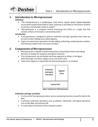
The microprocessor can be divided into three segments as shown in the figure,
Arithmetic/logic unit (ALU), register array, and control unit.
These three segment is responsible for all processing done in a computer
Figure: Components of Microprocessor
Arithmetic and logic unit (ALU)
It is the unit of microprocessor where various computing functions are performed on the
data.
It performs arithmetic operations such as addition, subtraction, and logical operations
such as OR, AND, and Exclusive-OR.
It is also known as the brain of the computer system.
Arithmetic
and Logical
Unit (ALU)
Register
Array
Control Unit
2. Unit 1 – Introduction to Microprocessor
2
Prof. Swati R. Sharma, CE Department | 3160712 – Microprocessor and Interfacing
Register array
It is the part of the register in microprocessor which consists of various registers identified
by letters such as B, C, D, E, H, and L.
Registers are the small additional memory location which are used to store and transfer
data and programs that are currently being executed.
Control unit
The control unit provides the necessary timing and control signals to all the operations in
the microcomputer.
It controls and executes the flow of data between the microprocessor, memory and
peripherals.
The control bus is bidirectional and assists the CPU in synchronizing control signals to
internal devices and external components.
This signal permits the CPU to receive or transmit data from main memory.
3. System bus (data, address and control bus).
This network of wires or electronic pathways is called the 'Bus'.
A system bus is a single computer bus that connects the major components of a computer
system.
It combines the functions of a data bus to carry information, an address bus to determine
where it should be sent, and a control bus to determine its operation.
The technique was developed to reduce costs and improve modularity.
Figure: System Bus
3. Unit 1 – Introduction to Microprocessor
3
Prof. Swati R. Sharma, CE Department | 3160712 – Microprocessor and Interfacing
Address Bus
It is a group of wires or lines that are used to transfer the addresses of Memory or I/O
devices.
It is unidirectional.
The width of the address bus corresponds to the maximum addressing capacity of the
bus, or the largest address within memory that the bus can work with.
The addresses are transferred in binary format, with each line of the address bus carrying
a single binary digit.
Therefore the maximum address capacity is equal to two to the power of the number of
lines present (2lines).
Data Bus
It is used to transfer data within Microprocessor and Memory/Input or Output devices.
It is bidirectional as Microprocessor requires to send or receive data.
Each wire is used for the transfer of signals corresponding to a single bit of binary data.
As such, a greater width allows greater amounts of data to be transferred at the same
time.
Control Bus
Microprocessor uses control bus to process data, i.e. what to do
with the selected memory location.
Some control signals are Read, Write and Opcode fetch etc.
Various operations are performed by microprocessor with the help of control bus.
This is a dedicated bus, because all timing signals are generated according to control
signal.
4. Unit 1 – Introduction to Microprocessor
4
Prof. Swati R. Sharma, CE Department | 3160712 – Microprocessor and Interfacing
4. Microprocessor systems with bus organization
Figure: Microprocessor systems with bus organization
To design any meaningful application microprocessor requires support of other auxiliary
devices.
In most simplified form a microprocessor based system consist of a microprocessor, I/O
(input/output) devices and memory.
These components are interfaced (connected) with microprocessor over a common
communication path called system bus. Typical structure of a microprocessor based
system is shown in Figure.
Here, microprocessor is master of the system and responsible for executing the program
and coordinating with connected peripherals as required.
Memory is responsible for storing program as well as data. System generally consists of
two types of memories ROM (Read only and non-volatile) and RAM (Read/Write and
volatile).
I/O devices are used to communicate with the environment. Keyboard can be example of
input devices and LED, LCD or monitor can be example of output device.
Depending on the application level of sophistication varies in a microprocessor based
systems. For example: washing machine, computer.