1. BREVIAR DE CALCUL CASA C3
CALCULATION SUMMARY HOME C3
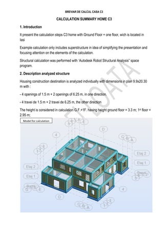
1. Introduction
It present the calculation steps C3 home with Ground Floor + one floor, wich is located in
Iasi
Example calculation only includes superstructure in idea of simplifying the presentation and
focusing attention on the elements of the calculation.
Structural calculation was performed with ‘Autodesk Robot Structural Analysis” space
program.
2. Description analyzed structure
Housing construction destination is analyzed individually with dimensions in plan 9.9x20.30
m with :
- 4 openings of 1.5 m + 2 openings of 6.25 m, in one direction.
- 4 travei de 1.5 m + 2 travei de 6.25 m, the other direction
The height is considered in calculation G.F.+1F. having height ground floor = 3.3 m; 1st floor =
2.95 m;
Model for calculation
2. BREVIAR DE CALCUL CASA C3
Materials:
Beams name Material Tip Grosime (cm) E (daN/m2)
GR_13 C20/25 constanta 13 3000000000
GR_15 C20/25 constanta 15 3000000000
GR_25 caramida 2 constanta 25 172500000
Coloumn name Sections material E (daN/m2)
S 25X25 □ C20/25 3000000000
S 55X40 T C20/25 3000000000
S 50X50 L C20/25 3000000000
S 40X25 I C20/25 3000000000
G 25x55 I C20/25 3000000000
CE 25x25 □ C20/31 3000000000
3. Assessments of the actions
3.1 Assessments of the permanents actions
Charging on the wooden floor and roof framing
nr. Name of material layers
thicness
(m)
ρ (kg/mc) t*ρ (daN/mp)
1 scandura 0.025 700 17.5
2 Vata minerala 0.15 70 10.5
3 gips carton 0.0125 1100 13.75+10
4 grinda lemn 0.0225 700 15.75
Total 67.5+150=220
Charging current on floor
nr. Name of material layers
thicness
(m)
ρ (kg/mc) t*ρ (daN/mp)
1 sapa mortar 0.05 2100 105
2 planseubetonarmat 0.13 2500 325
3 gips carton 0.0125 1100 13.75+10
Total 453.75
Note: because the calculation program automatically take charge of the concrete slab,
3. BREVIAR DE CALCUL CASA C3
incarcareaaditionala of planseuva be 128.75 + daN / m2
Charging time of partition walls
nr.
Crt.
Denumirestrat de material d *h(m2) ρ (kg/mc) d*h*ρdaN/m
1 tencuiala mortar 0.015*3.15 1900 89.78
2 zidariecaramida GVP 0.115*3.15 900 327
3 tencuiala mortar 0.015*3.15 1900 89.78
Total 507
Charging on interior walls
Note: loading the external walls are taken automatically in the design software
Charging time of dig
4. BREVIAR DE CALCUL CASA C3
Charging on wooden floor and roof framing
Payload
5. BREVIAR DE CALCUL CASA C3
3.2 Assessment of the action variables
(1) Evaluation of snow (CR 1-1-3-2005)
Characteristic value of snow load on the roof,sk :
sk =μi x ce x ct x s0k ((2.3)- CR-1-1-3-2005)
in wich:
μi - form factor for snow load on the roof which is determined based on the shape of the
roof;
μi = μ1=0,8 – roof with 2 slopes (Tabel 3.1, pct. 3.1);
ce - exposure coefficient of construction site;
ce = 1 - roof with partial exposure (Tabel 2.1, pct.2.2);
ct – the thermal coefficient;
ct = 1,0 – the usual roof insulation (pct. 2.2);
6. BREVIAR DE CALCUL CASA C3
s0k – characteristic value of snow load on the ground [kN/m2];
s0k=2,5kN/m2
- emplacement City Iasi (tabele A1, Annex A);
sk =1 x 0,8 x 1,0 x 2,5 = 2.0 kN / m
7. BREVIAR DE CALCUL CASA C3
Table combinations
Load combinations
Name Type Permanent Snow payload seism
+
seism
-
Observation
1 Modala - 1,00 0,40 0,40 0 0
2 SLU1 SLU 1,35 1,05 1,50 0 0
3 SLU2 SLU 1,35 1,50 1,05 0 0
4 SLU4 SLU 1,00 0,40 0,40 1,00 0
5 SLU5 SLU 1,00 0,40 0,40 0 1,00
6 SLS SLS 1,00 0,4 0,4 0,6
3.2 Evaluation of accidental actions
(1) Evaluation of earthquake (P100-1/2013)
Adopt „ Calculation method response spectrum” (paragraph 4.5.3.3.from P100-1/2006).
Fbk base shear force applied to the direction of action of seismic movement of vibration
mode is k (Forţa tăietoare de bază Fb,k aplicată pe direcţia de acţiune a mişcării seismice
în modul propriu de vibraţie k este):
Fb,k = ϒI x Sd x Tk x mk ((4.8 – P100)-1/2006)
unde:
mk - is effective modal mass mode of vibration associated with k;
Tk - during own mode of vibration k;
In wich:
ϒI=0.8 – is important factor of building-exposure; importance class IV (Table 4.2);
Sd T - design spectrum for acceleration (spectrul de proiectare pentru acceleraţii),
expressed in m/s2;
Tc=0,7s si TB=0,07s – Iasi site(pct. 3.1, fig. 3.2);
Sd(T )= ag x β(T)/q
because T>TB (T fundamental period is estimated at 0,75s 0,85s);
ag =0,25g=0,2x 10=2,50 - design ground acceleration;
8. BREVIAR DE CALCUL CASA C3
Iasi site ( fig. 3.1);
q=6.75 – behavior factor structure (table 5.1);
β(T) – elastic response spectrum normalized by period Corner (spectru normalizat de
răspuns elastic funcţie de perioada de colt);
In the computer program used insert elastic response spectra normalized to Tc=0,7s
4. Evaluation masses
For modal analysis of the structure, mass (m) assessing the combination of loads, in table
4.1 from CR 0-2005:
Predimensioning structure elements, It is based on design experience and relationships
simplified calculation to determine the state of stresses and deformations in the structural
elements.
5. Modal analysis
5.1 Elastic mode
Analyzed structure for structural modeling was done with a spreadsheet program space.
Three-dimensional model is made of reinforced concrete floors that were modeled with
finite elements membrane (in “Autodesc Robot Structural Analysis”).
5.2 Steps modal analysis:
1. The geometrical configuration of the structure;
2. Defining materials. (specific weight, mass, modulus of elasticity, Poisson’s ratio, yield
strength and tensile strength);
3. Defining sections (section type with dimensions);
4. Deshing structure (discretizarea sectiunii) – all bars were defined structure with finite
elements beam;
5. Defining plate reinforced concrete finite element membrane;
6. Defining response;
7. Defining source masses;
8. Assigning connections with the land structure;
9. Assigning connections between elements (if there is articulated links);
9. BREVIAR DE CALCUL CASA C3
10. Assign section for each element type;
11. Assign element load (Atribuirea incarcarilor pe elemente);
12. Assigning the number of degrees of freedom (Atribuirea numărului gradelor de
libertate);
13. Assigning parameters modal analysis (number of vibration modes) [( Atribuirea
parametrilor analizei modale (numărului de moduri proprii de vibraţie)];
Define many vibration modes up when their modal amount to be at least 90% of the total, in
both directions.
14. Load assumptions for defining spectral response on the two main directions. (UX si UY)
– are defined, at this stage it is necessary to calculate equivalent static;
15. Defining assumptions loading;
16. Defining load combinations;
17. Linear static analysis is running;
It follows its own dynamic characteristics of the structure (the own vibration period, vectors
and eigenvalues (vectori si valori proprii), participation factors masses).
Moment sections in slab
10. BREVIAR DE CALCUL CASA C3
Floor map:
Calculation model
Bending moments in xx direction
11. BREVIAR DE CALCUL CASA C3
Bending moments in yy direction
Frame spindle 3
16. BREVIAR DE CALCUL CASA C3
Cutting force columns.
Axial force in coloumns
17. BREVIAR DE CALCUL CASA C3
6. Relative displacements allowable level
(1) Checking level relative displacement limit state service, It aims at maintaining the main
functions of the building in case of earthquakes that have a higher probability of occurrence
than the design seismic action, Disposal without degradation or whose costs are
excessively high compared to the cost structure;
(2) In the case of special purpose buildings (ex.central nuclear, central electric, buildings
housing with sensitive equipment) Further checks can be made more severe limitation of
movements than those referred to. 6(3);
(3) relative displacement level verification is done with the relationship:
drS.L.S≤dr,a,S .L.S
in wich:
drS .L.S=ν*q*dr
drS.L.S= level relative displacement under seismic action;
ν = reduction factor that takes into account the shorter return period of the seismic action.
The factor value is :
0,4 buildings falling in classes I and II of importance
0,5 buildings falling in classes III and IV of importance
q= behavior factor specific type of structure. ( see tab. 6.3)
The relative displacement level determined by calculating the elastic static load r d group
that contains the earthquake. (according with Cap.4);
dr,a,S .L.S = the allowable amount of relative displacement level, Current buildings that cases
take: dr,a,S .L.S =0.05*h= 0.05*330=1.65 cm
Moving in the x direction.