Downloaded 229 times
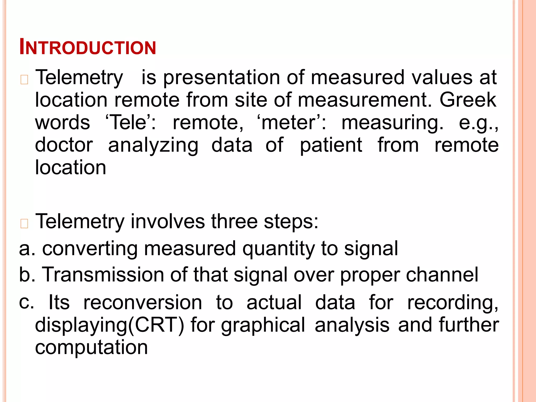
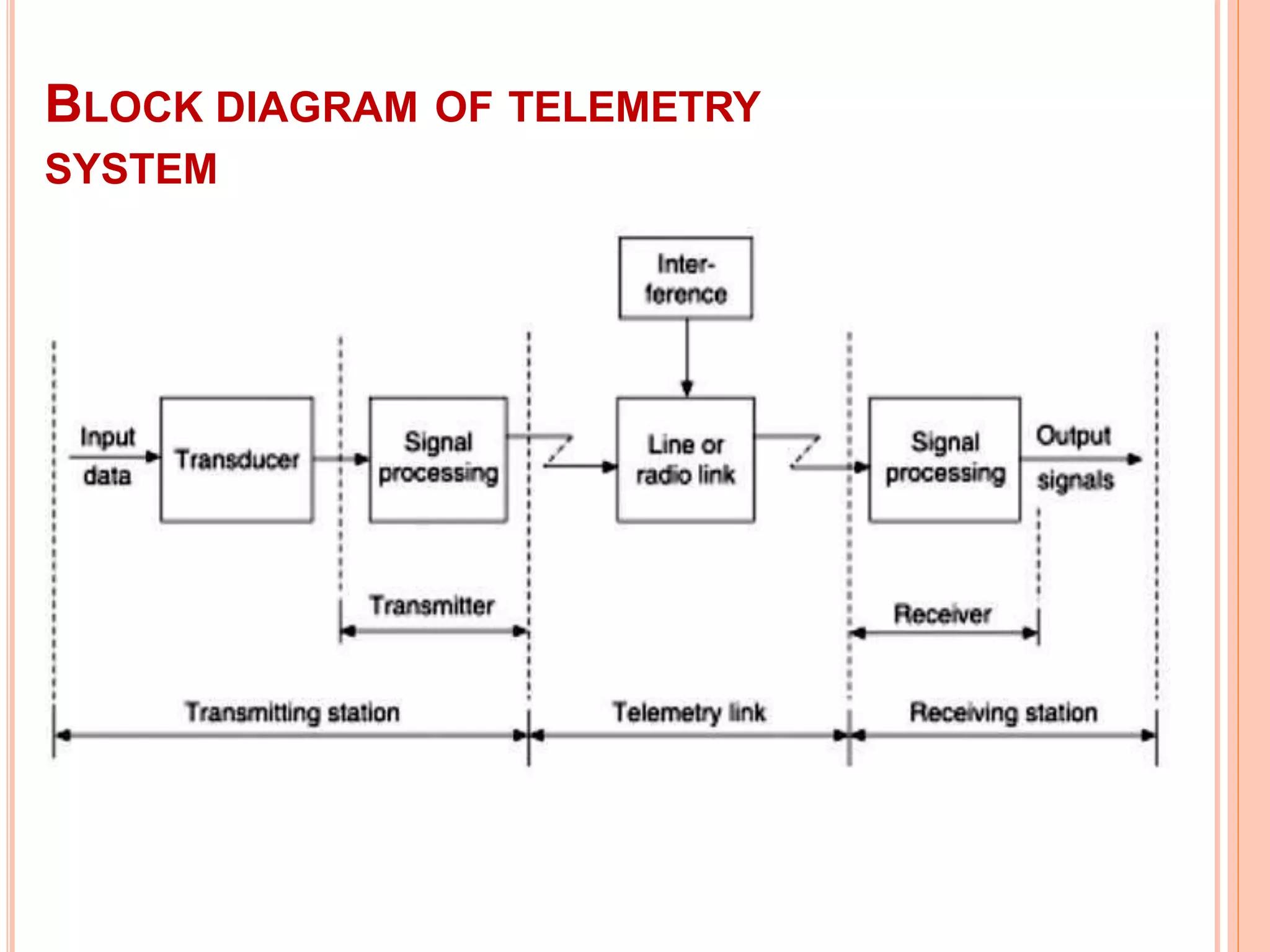
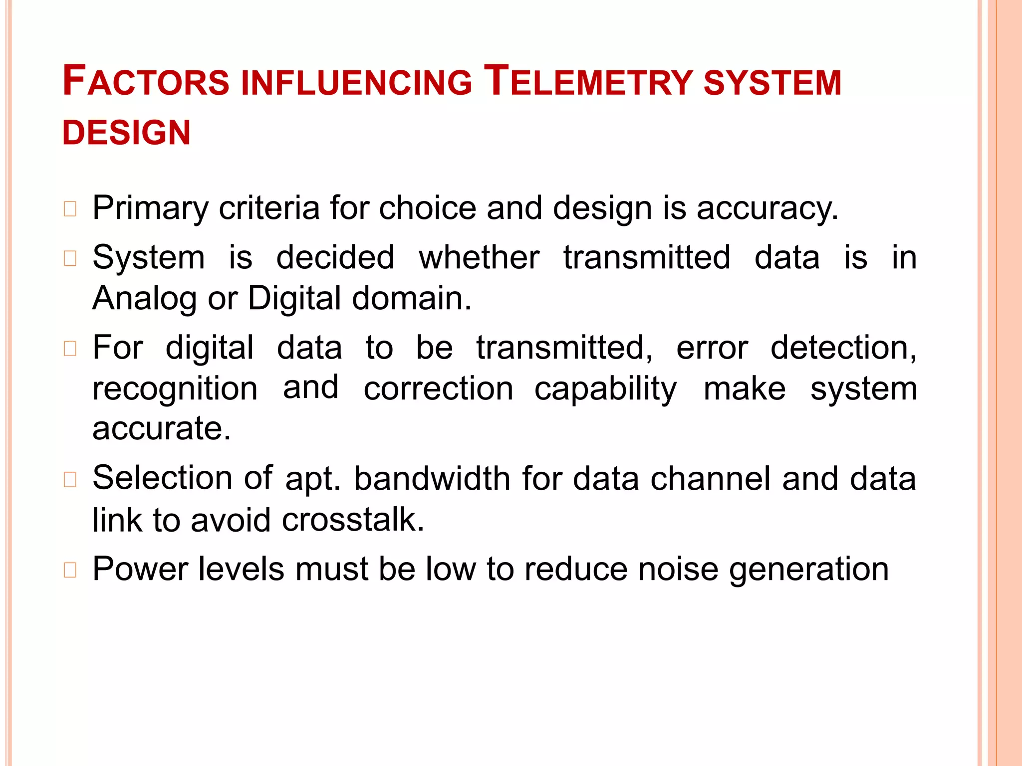


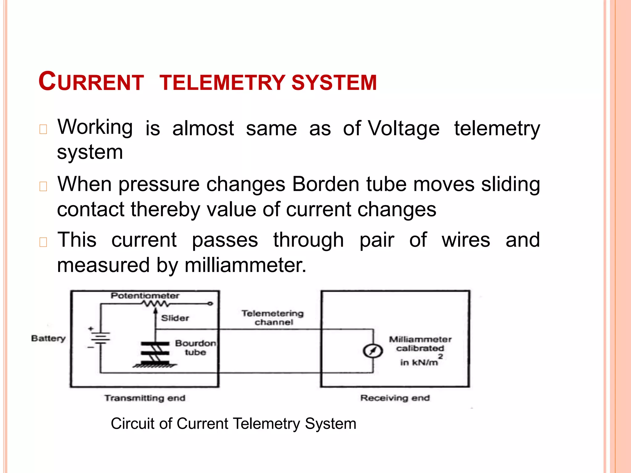


Telemetry involves measuring values at a remote location and transmitting the data to another location. It involves three steps - measuring a value, converting it to a signal, transmitting the signal, and reconverting it back to the original data. Factors like accuracy, whether the data is analog or digital, error detection/correction, and bandwidth influence telemetry system design. There are two main types - landline systems which use wires/cables over short distances, and radio frequency systems which use radio links from 1km to beyond 50km. Landline systems transmit current or voltage and have simple circuitry but limited range. Radio frequency systems transmit via radio links and are used for long range applications like spacecraft. Modulation schemes include amplitude modulation for