2. LECTURE 1
CHAPTER 11,
HEAT EXCHANGERS
Presented By
Dr. Saeed Abdullah
Mechatronics Engineering L200 & Aerospace and Craft L300
Faculty of Engineering
Zagazig University
2021-2022
2
3. 3
Introduction
Heat exchangers are devices that facilitate the exchange of heat
between two fluids that are at different temperatures while keeping
them from mixing with each other.
Heat transfer in a heat exchanger usually involves convection in each
fluid and conduction through the tube wall separating the two fluids.
Overall heat transfer coefficient U that accounts for the contribution of
all these effects on heat transfer (convection + conduction).
The rate of heat transfer, 𝑄 between the two fluids at a location in a
heat exchanger depends on the magnitude of the temperature
difference at that location, which varies along the heat exchanger.
Heat exchangers are manufactured in a variety of types, and thus we
start this chapter with the classification of heat exchangers.
4. 4
1- Determination of the overall heat transfer coefficient in heat
exchangers.
2- Determination of the log mean temperature difference (LMTD) for
some configurations.
3- Introduce the correction factor 𝐹 to account for the deviation of the
mean temperature difference from the LMTD in complex
configurations.
4- Discuss the effectiveness–NTU method, which enables us to analyze
heat exchangers when the outlet temperatures of the fluids are not
known.
5- Finally, we discuss the selection of heat exchangers.
What Will We Study?
5. 5
1- TYPES OF HEAT EXCHANGERS (Double-Pipe Heat Exchanger)
The simplest type of heat exchanger consists of two concentric tubes of
different diameters called the double-pipe heat exchanger.
Two types of flow arrangement
are possible in a double-pipe
heat exchanger:
1-Parallel flow, both the hot
and cold fluids enter the heat
exchanger at the same end and
move in the same direction.
2-Counter flow, the hot and
cold fluids enter the heat
exchanger at opposite ends and
flow in opposite directions.
6. 6
2- Cross-flow Heat Exchanger
1- In compact heat exchangers, the two fluids usually move perpendicular
to each other, and such flow configuration is called cross-flow.
2- The cross-flow is further classified as unmixed and mixed flow.
3- Compact heat exchangers designed to
realize a large heat transfer surface area
per unit volume.
4- β : is called the area density, the ratio of
the heat transfer surface area, 𝐴𝑠 of a
heat exchanger to its volume, 𝑉.
𝛽 =
𝐴𝑠
𝑉𝑜𝑙𝑢𝑚𝑒
5- β > 700 m2/m3 is classified as compact.
Example of compact heat exchangers is car
radiators (𝛽 ≈ 1000 𝑚2
/𝑚3
)
7. 7
1-Baffles are used to establish a cross-flow and to induce turbulent mixing of the
shell-side fluid, both of which enhance convection.
3- Shell-and-Tube Heat Exchangers
2- Shell-and-tube heat exchangers are further classified according to the number of
shell and tube passes involved.
Shell-and-tube heat exchangers
contain a large number of tubes
(sometimes several hundred)
packed in a shell with their axes
parallel to that of the shell.
8. 8
3- Shell-and-Tube Heat Exchangers
Heat exchangers are often given specific names to reflect the specific
application for which they are used.
1. Condenser is a heat exchanger in which one of the fluids is cooled
and condenses as it flows through the heat exchanger.
2. Boiler is another heat exchanger in which one of the fluids
absorbs heat and vaporizes.
3. Radiator is a heat exchanger that transfers heat from the hot fluid to
the surrounding space by radiation.
9. 11–2 ■ THE OVERALL HEAT TRANSFER COEFFICIENT, U
9
where: 𝑘 : The thermal conductivity of the tube wall material.
𝐿 : The tube length.
𝐴𝑖 : The area of the inner surface of the wall
that separates the two fluids.
𝐴𝑜 : The area of the outer surface of the wall.
𝑅𝑖 =
1
ℎ𝑖.𝐴𝑖
, 𝑅𝑤𝑎𝑙𝑙 =
ln 𝐷𝑜/𝐷𝑖
2.𝜋.𝐿.𝑘
, 𝑅𝑜 =
1
ℎ𝑜.𝐴𝑜
𝑅𝑡𝑜𝑡𝑎𝑙 = 𝑅𝑖 + 𝑅𝑤𝑎𝑙𝑙 + 𝑅𝑜
𝐴𝑖 = 𝜋. 𝐷𝑖. 𝐿 𝐴𝑜 = 𝜋. 𝐷𝑜. 𝐿
𝑅𝑡𝑜𝑡𝑎𝑙 =
1
ℎ𝑖.𝐴𝑖
+
ln 𝐷𝑜/𝐷𝑖
2.𝜋.𝐿.𝑘
+
1
ℎ𝑜.𝐴𝑜
&
10. 10
The rate of heat transfer between the two fluids as:
where 𝐴𝑠 : The surface area.
𝑈 : The overall heat transfer coefficient, W/m2·K.
When: 1-The wall thickness of the tube is small
2-The thermal conductivity of the tube material is high
3-The thermal resistance of the tube is negligible
(Rwall ≈ 0)
𝑄 =
∆𝑇
𝑅
= 𝑈. 𝐴𝑠. ∆𝑇𝑚 = 𝑈𝑖. 𝐴𝑖. ∆𝑇𝑚 = 𝑈𝑜. 𝐴𝑜. ∆𝑇𝑚
11–2 ■ THE OVERALL HEAT TRANSFER COEFFICIENT, U
𝑅 =
1
𝑈. 𝐴𝑠
=
1
𝑈𝑖. 𝐴𝑖
=
1
𝑈𝑜. 𝐴𝑜
=
1
ℎ𝑖. 𝐴𝑖
+
ln 𝐷𝑜/𝐷𝑖
2. 𝜋. 𝐿. 𝑘
+
1
ℎ𝑜. 𝐴𝑜
1
𝑈
≈
1
𝑈𝑖
=
1
𝑈𝑜
=
1
ℎ𝑖
+
1
ℎ𝑜
𝐷𝑜 ≈ 𝐷𝑖 , 𝐴𝑖 ≈ 𝐴𝑜
11. 11
Fouling Factor
where ∶ 𝑅𝑓,𝑖 and 𝑅𝑓,𝑜 are the fouling factors
at those surfaces.
1
𝑈. 𝐴𝑠
=
1
𝑈𝑖. 𝐴𝑖
=
1
𝑈𝑜. 𝐴𝑜
=
1
ℎ𝑖. 𝐴𝑖
+
𝑅𝑓,𝑖
𝐴𝑖
+
ln 𝐷𝑜/𝐷𝑖
2. 𝜋. 𝐿. 𝑘
+
𝑅𝑓,𝑜
𝐴𝑜
+
1
ℎ𝑜. 𝐴𝑜
11–2 ■ THE OVERALL HEAT TRANSFER COEFFICIENT, U
12. 12
𝑄 = 𝑚ℎ. 𝑐𝑝,ℎ. 𝑇ℎ,𝑖 − 𝑇ℎ,𝑜 = 𝑚𝑐. 𝑐𝑝,𝑐. 𝑇𝑐,𝑜 − 𝑇𝑐,𝑖 = 𝑈. 𝐴. ∆𝑇𝑚
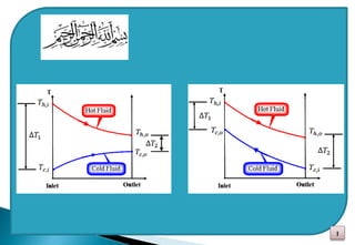
∆𝑇𝑚 =
∆𝑇1 − ∆𝑇2
𝑙𝑛
∆𝑇1
∆𝑇2
∆𝑇1 = 𝑇ℎ,𝑖 − 𝑇𝑐,𝑜
∆𝑇2 = 𝑇ℎ,𝑜 − 𝑇𝑐,𝑖
A form of Newton’s Law of Cooling may be applied to heat exchangers by
using a log-mean value of the temperature difference between the two
fluids:
The Log Mean Temperature Difference
Log Mean Temperature Difference
where:
Counterflow- Heat Exchanger
18. 18
Exp. 2: A counter-flow double-pipe heat exchanger is to heat water from 20 oC
to 80 oC at a rate of 1.2 kg/s. The heating is to be accomplished by geothermal
water available at 160 oC at a mass flow rate of 2 kg/s.
The inner tube is thin-walled and has a diameter of 1.5 cm. If the overall heat
transfer coefficient of the heat exchanger is 640 W/m2.K, Determine:
1-The length of the heat exchanger, 𝐿 required to achieve the desired heating.
19. 19
𝑄 = 𝑚ℎ. 𝑐𝑝,ℎ. 𝑇ℎ,𝑖 − 𝑇ℎ,𝑜 = 𝑚𝑐.𝑐𝑝,𝑐. 𝑇𝑐,𝑜 − 𝑇𝑐,𝑖 = 𝑈. 𝐴. ∆𝑇𝑚
𝑄 = 𝑚𝑐. 𝑐𝑝,𝑐. 𝑇𝑐,𝑜 − 𝑇𝑐,𝑖 = 2 𝑥 4.31 𝑥 (160 − 𝑇ℎ,𝑜) = 1.2 x 4.18 x (80-20) = 301 kW
𝑇ℎ,𝑜 = 125 oC
∆𝑇𝑚 =
∆𝑇1−∆𝑇2
𝑙𝑛
∆𝑇1
∆𝑇2
=
80−105
ln(
80
105
)
= 91.8 oC
∆𝑇1 = 𝑇ℎ,𝑖 − 𝑇𝑐,𝑜= 160 - 80 = 80 oC
∆𝑇2 = 𝑇ℎ,𝑜 − 𝑇𝑐,𝑖 = 125-20 = 105 oC
2- Log Mean Temperature Difference:
𝑄 = 𝑈. 𝐴𝑠. ∆𝑇𝑚 = 301 𝑘𝑊
𝐴𝑠 =
𝑄
𝑈. ∆𝑇𝑚
=
301𝑥103
640 𝑥 91.9
= 5.12 𝑚2
3- Then the surface area of the heat exchanger is determined to be:
4- the length of the tube must be
𝐴𝑠 = 𝜋. 𝐷. 𝐿 = 𝜋 𝑥 0.015 𝑥 𝐿 = 5.12 𝑚2
𝐿 = 109 𝑚
20. 20
A 2-shell passes and 4-tube passes heat exchanger is used to heat glycerin from 20 oC to
50 oC by hot water, which enters the thin-walled 2-cm-diameter tubes at 80 oC and leaves
at 40 oC. The total length of the tubes in the heat exchanger is 60 m. The convection heat
transfer coefficient is 25 W/m2.K on the glycerin (shell) side and 160 W/m2.K on the
water (tube) side.
Determine the rate of heat transfer in the heat exchanger
(a) before any fouling and
(b) after fouling with a fouling factor of 0.0006 m2.K/W occurs on the outer surfaces of
the tubes.
21. 21
𝐴𝑠 = 𝜋. 𝐷. 𝐿 = 𝜋 𝑥 0.02 𝑥 60 = 3.77 𝑚2
𝑄 = 𝑈. 𝐴𝑠. 𝐹. ∆𝑇𝑚,𝐶𝐹
where F is the correction factor and ∆Tm,CF is the log mean temperature difference
for the counter-flow arrangement. These two quantities are determined from:
∆𝑇1 = 𝑇ℎ,𝑖 − 𝑇𝑐,𝑜 = 80 − 50 = 30 𝑜
𝐶
∆𝑇2 = 𝑇ℎ,𝑜 − 𝑇𝑐,𝑖 = 40 − 20 = 20 𝑜
𝐶
∆𝑇𝑚,𝐶𝐹 =
∆𝑇1 − ∆𝑇2
𝑙𝑛
∆𝑇1
∆𝑇2
=
30 − 20
𝑙𝑛
30
20
= 24.7 𝑜
𝐶
𝑃 =
𝑡2 − 𝑡1
𝑇1 − 𝑡1
=
40 − 80
20 − 80
= 0.67
𝑅 =
𝑇1 − 𝑇2
𝑡2 − 𝑡1
=
20 − 50
40 − 80
= 0.75
𝐹 = 0.91
22. 22
(a) In the case of no fouling, the overall heat transfer coefficient U is:
1
𝑈
=
1
ℎ𝑖
+
1
ℎ𝑜
=
1
160
+
1
25
𝑈 = 21.6 𝑊/𝑚2
. 𝐾
Then the rate of heat transfer becomes:
𝑄 = 𝑈. 𝐴𝑠. 𝐹. ∆𝑇𝑚,𝐶𝐹 = 21.6 x 3.77 x 0.91 x 24.7 = 1830 W
(b) When there is fouling on one of the surfaces, we have:
1
𝑈
=
1
ℎ𝑖
+ 𝑅𝑓 +
1
ℎ𝑜
=
1
160
+ 0.0006 +
1
25
𝑈 = 21.3 𝑊/𝑚2
. 𝐾
Then the rate of heat transfer becomes:
𝑄 = 𝑈. 𝐴𝑠. 𝐹. ∆𝑇𝑚,𝐶𝐹 = 21.3 x 3.77 x 0.91 x 24.7 = 1805 W
23. 23
The correction factor is less than unity for a cross-flow and multipass
shell and-tube heat exchanger. That is, 𝐹 ≤ 1
24. The correction factor is less than unity for a cross-flow and multipass
shell and-tube heat exchanger. That is, 𝐹 ≤ 1
24