SlideShare a Scribd company logo
1 of 15
Download to read offline
1
Heat Exchangers
The process of heat exchange between two fluids that are at different temperatures and separated
by a solid wall occurs in many engineering applications. The device used to heat exchange is
termed a heat exchanger, and specific applications may be found in space heating and air
conditioning, power production, waste heat recovery, and chemical processing.
In this chapter our objectives are to introduce performance parameters for assessing the
efficacy of a heat exchanger and to develop methodologies for designing a heat exchanger or for
predicting the performance of an existing exchanger operating under prescribed conditions.
Heat Exchanger Types
Heat exchangers are typically classified according to flow arrangement and type of
construction.
1- Parallel-flow heat exchangers; for which the hot and cold fluids move in the same
direction in a concentric tube (or double-pipe) construction.
2- Counter flow heat exchangers; the fluids enter at opposite ends, flow in opposite
directions, and leave at opposite ends.
3- Cross flow heat exchangers; the fluids may move in (perpendicular to each other), as
shown by the finned and un-finned tubular heat exchangers.
Fig.1 Concentric tube heat exchangers. (a) Parallel flow. (b) Counterflow.
Fig.2 Cross-flow heat exchangers. (a) Finned with both fluids unmixed.
(b) Unfinned with one fluid mixed and the other unmixed.
2
In Fig. 2a, the cross-flowing fluid is said to be unmixed because the fins inhibit motion in a
direction (y). In this case the cross-flowing fluid temperature varies with x and y. In the finned
exchanger both fluids are unmixed.
In contrast, for the unfinned tube bundle of Fig. 2b, fluid motion, hence mixing, in the
transverse direction is possible, and temperature variations are primarily in the main-flow
direction. The cross-flowing fluid is mixed and the tube fluid is unmixed in the unfinned
exchanger.
4- Shell and tube heat exchangers
5- Compact heat exchangers
A special and important class of heat exchangers is used to achieve a very large heat
transfer surface area per unit volume ( ≥ 400 m2
/m3
for liquids and ( ≥ 700 m2
/m3
for
gases)
Fig.3 Shell-and-tube heat exchanger with one shell pass and one tube pass.
Fig.4 Shell-and-tube heat exchangers. (a) One shell pass and two tube passes.
(b) Two shell passes and four tube passes.
3
Overall Heat Transfer Coefficient
For a wall separating two fluid streams, the overall heat transfer coefficient may be expressed
as
( )
( )
( )
Where, c and h refer to the cold and hot fluids, respectively. The deposition of a film or scale on
the surface can greatly increase the resistance to heat transfer between the fluids. This effect can
be treated by introducing an additional thermal resistance, termed the fouling factor, Rf. Its value
depends on the operating temperature, fluid velocity, and length of service of the heat
exchanger.
For surface fouling and fin (extended surface) effects, the overall heat transfer coefficient is
modified as follows:
( ) ( )
( )
( ) ( )
The quantity ηo is termed the overall surface efficiency or temperature effectiveness of a finned
surface. It is defined such that, for the hot or cold surface without fouling, the heat transfer rate
is
( )
Where, Tb is the base surface temperature, and A is the total (fin plus exposed base) surface
area.
Fig.5 Compact heat exchanger cores.
Plate–fin
(d) Single pass (e) Multipass
Fin-tube
4
( )
For the unfinned, tubular heat exchangers
( )
Where, subscripts i and o refer to inner and outer tube surfaces ( ), which
may be exposed to either the hot or the cold fluid.
Heat Exchanger Analysis: Use of the Log Mean Temperature Difference
To design or to predict the performance of a heat exchanger, it is essential to relate the total
heat transfer rate to quantities such as the inlet and outlet fluid temperatures, the overall heat
transfer coefficient, and the total surface area for heat transfer.
Applying overall energy balances to the hot and cold fluids. In particular, if q is the total rate of
heat transfer between the hot and cold fluids and there is negligible heat transfer between the
exchanger and its surroundings, the steady flow energy equation, gives
̇ ( ) ̇ ( )
Where, i is the fluid enthalpy. The subscripts h and c refer to the hot and cold fluids, whereas the
subscripts i and o designate the fluid inlet and outlet conditions. If the fluids are not undergoing
a phase change and constant specific heats are assumed, these expressions reduce to
̇ ( ) ̇ ( )
Where, ∆Tlm is an appropriate mean temperature difference.
The Parallel-Flow Heat Exchanger
The log mean temperature difference is
Fig.6 Overall energy balances for the hot and cold fluids
of a two-fluid heat exchanger.
Fig.7 Temperature distributions for a parallel-flow heat exchanger.
5
( ⁄ ) ( ⁄ )
For the parallel flow exchanger the temperature differences must now be defined as
The Counterflow Heat Exchanger
For the counter-flow exchanger the temperature differences must now be defined as
Note that, for the same inlet and outlet temperatures, the log mean temperature difference for
counter flow exceeds that for parallel flow, Tm,CF >Tm,PF. Hence the surface area required to
effect a prescribed heat transfer rate q is smaller for the counter-flow than for the parallel-flow
arrangement, assuming the same value of U. Also note that Tc,o can exceed Th,o for counter flow
but not for parallel flow.
Special Operating Conditions
Fig.8 Temperature distributions for a counter-flow heat exchanger.
Fig.9 Special heat exchanger conditions.
6
1- Condensation occurs at constant temperature, and, for all practical purposes, Ch→∞. For
a heat exchanger in which the hot fluid has a heat capacity rate, ̇ which is
much larger than that of the cold fluid, ̇ For this case the temperature of the
hot fluid remains approximately constant throughout the heat exchanger, while the
temperature of the cold fluid increases.
2- In an evaporator or a boiler, the cold fluid that experiences a change in phase and
remains at a nearly uniform temperature (Cc→∞).
3- The third special case involves a counter-flow heat exchanger for which the heat
capacity rates are equal (Ch = Cc). The temperature difference ∆T must then be constant
throughout the exchanger, in which case ∆T1 =∆T2 =∆Tlm.
EXAMPLE.1
A counter-flow, concentric tube heat exchanger is used to cool the lubricating oil for a large
industrial gas turbine engine. The flow rate of cooling water through the inner tube (Di =25 mm)
is 0.2 kg/s, while the flow rate of oil through the outer annulus (Do = 45 mm) is 0.1 kg/s. The oil
and water enter at temperatures of 100 and 30o
C, respectively. How long must the tube be made
if the outlet temperature of the oil is to be 60o
C?
SOLUTION
Known: Fluid flow rates and inlet temperatures for a counter-flow, concentric tube heat
exchanger of prescribed inner and outer diameter.
Find: Tube length to achieve a desired hot fluid outlet temperature.
Schematic:
Assumptions:
1. Negligible heat loss to the surroundings.
2. Negligible kinetic and potential energy changes.
3. Constant properties.
4. Negligible tube wall thermal resistance and fouling factors.
5. Fully developed conditions for the water and oil (U independent of x).
Properties: unused engine oil (Th = 80o
C = 353 K): cp= 2131 J/kg. K, µ = 3.25 x 10⁻²
N. s/m2
,
k = 0.138 W/m. K.Water (Tc =35o
C): cp =4178 J/kg. K, µ = 725 x 10-6
N.s/m2
, k = 0.625 W/m.
K, Pr = 4.85.
Analysis: The required heat transfer rate may be obtained from the overall energy balance for
the hot fluid.
̇ ( ) ( )
The water outlet temperature is
̇
7
The required heat exchanger length may now be obtained from
( ) ( )
( ) ( ) ( )
The overall heat transfer coefficient is
( ) ( )
For water flow through the tube,
̇
( )
⁄
( ) ( )
For the flow of oil through the annulus, the hydraulic diameter is, Dh = Do - Di = 0.02 m, and the
Reynolds number is
( )
( )
̇
( )
( )
U = 38.1 W/m2
.K
( )( )
Heat Exchanger Analysis: The Effectiveness–NTU Method
It is a simple matter to use the log mean temperature difference (LMTD) method of heat
exchanger analysis when the fluid inlet temperatures are known and the outlet temperatures are
specified or readily determined from the energy balance expressions. The value of ∆Tlm for the
exchanger may then be determined. However, if only the inlet temperatures are known, use of
the LMTD method requires a cumbersome iterative procedure. It is therefore preferable to
employ an alternative approach termed the effectiveness–NTU (or NTU) method.
Definitions
To define the effectiveness of a heat exchanger, we must first determine the maximum possible
heat transfer rate, qmax, for the exchanger. This heat transfer rate could, in principle, be achieved
in a counter-flow heat exchanger of infinite length. The cold fluid would then experience the
larger temperature change, and since L→∞, it would be heated to the inlet temperature of the
hot fluid (Tc,o = Th,i).
( )
If Ch < Cc, the hot fluid would experience the larger temperature change and would be cooled to
the inlet temperature of the cold fluid (Th,o= Tc,i).
( )
( )
8
It is now logical to define the effectiveness, ε, as the ratio of the actual heat transfer rate for a
heat exchanger to the maximum possible heat transfer rate:
( )
( )
( )
( )
( )
( )
The number of transfer units (NTU) is a dimensionless parameter that is widely used for heat
exchanger analysis and is defined as
The heat capacity ratio Cr , is Cr = Cmin/Cmax
9
Fig.10 Effectiveness of a parallel flow
heat exchanger.
Fig.11 Effectiveness of a counter-flow
heat exchanger.
10
Fig.12 Effectiveness of a shell-and tube heat
exchanger with one shell and any multiple of two
tube passes (two, four, etc. tube passes).
Fig.13 Effectiveness of a shell-and tube heat
exchanger with two shell passes and any
multiple of four tube passes (four, eight, etc.
tube passes) ( with n = 2).
Fig.14 Effectiveness of a single pass, cross-flow
heat exchanger with both fluids unmixed.
Fig.15 Effectiveness of a single pass, cross-flow
heat exchanger with one fluid mixed and the
other unmixed.
11
EXAMPLE 2
Hot exhaust gases, which enter a finned-tube, cross-flow heat exchanger at 300o
C and leave at
100o
C, are used to heat pressurized water at a flow rate of 1 kg/s from 35 to 125o
C. The overall
heat transfer coefficient based on the gas-side surface area is Uh = 100 W/m2
. K. Determine the
required gas-side surface area Ah using the NTU method.
SOLUTION
Known: Inlet and outlet temperatures of hot gases and water used in a finned-tube, cross flow
heat exchanger. Water flow rate and gas-side overall heat transfer coefficient.
Find: Required gas-side surface area.
Schematic:
Assumptions:
1. Negligible heat loss to the surroundings and kinetic and potential energy changes.
2. Constant properties.
Properties: Water: Tc = 80 o
C cp,c = 4197 J/kg. K.
Analysis: The required surface area may be obtained from knowledge of the number of transfer
units, which, in turn, may be obtained from knowledge of the ratio of heat capacity
rates and the effectiveness. To determine the minimum heat capacity rate, we begin
by computing.
̇
̇ ( ) ̇ ( )
̇ [ ] [ ]
( ) ( )
The actual heat transfer rate is
( ) ( )
Hence the effectiveness is
12
Heat Exchanger Design and Performance Calculations
Two general types of heat exchanger problems are commonly encountered by the practicing
engineer. In the heat exchanger design problem, the fluid inlet temperatures and flow rates, as
well as a desired hot or cold fluid outlet temperature, are prescribed.
The design problem is then one of specifying a specific heat exchanger type and determining
its size—that is, the heat transfer surface area A—required to achieve the desired outlet
temperature.
In a heat exchanger performance calculation, an existing heat exchanger is analyzed to
determine the heat transfer rate and the fluid outlet temperatures for prescribed flow rates
and inlet temperatures.
For heat exchanger design problems, the NTU method may be used by first calculating ε and
(Cmin/Cmax). The appropriate equation (or chart) may then be used to obtain the NTU value,
which in turn may be used to determine A.
For a performance calculation, the NTU and (Cmin/Cmax) values may be computed and ε may
then be determined from the appropriate equation (or chart) for a particular exchanger type.
Since qmax may also be computed, it is a simple matter to determine the actual heat transfer rate
from q = ε qmax. Both fluid outlet temperatures may then be determined.
13
Sheet
1- In a fire-tube boiler, hot products of combustion flowing through an array of thin-walled
tubes are used to boil water flowing over the tubes. At the time of installation, the overall
heat transfer coefficient was 400 W/m2
. K. After 1 year of use, the inner and outer tube
surfaces are fouled, with corresponding fouling factors of Rƒ,i = 0.0015 and Rƒ,o= 0.0005
m2
. K/W, respectively. Should the boiler be scheduled for cleaning of the tube surfaces?
2- A type-302 stainless steel tube of inner and outer diameters Di = 22 mm and Do = 27
mm, respectively, is used in a cross-flow heat exchanger. The fouling factors, Rƒ, for the
inner and outer surfaces are estimated to be 0.0004 and 0.0002 m2
. K/W, respectively.
Determine the overall heat transfer coefficient based on the outside area of the tube, Uo.
3- A finned-tube, cross-flow heat exchanger is to use the exhaust of a gas turbine to heat
pressurized water. Laboratory measurements are performed on a prototype version of the
exchanger, which has a surface area of 10m2
, to determine the overall heat transfer
coefficient as a function of operating conditions. Measurements made under particular
conditions, for which ̇ = 2 kg/s, Th,i = 325 o
C, ̇ = 0.5 kg/s, and Tc,i = 25o
C, reveal a
water outlet temperature of Tc,o = 150 o
C. What is the overall heat transfer coefficient of
the exchanger?
4- A process fluid having a specific heat of 3500 J/kg .K and flowing at 2 kg/s is to be
cooled from 80o
C to 50o
C with chilled water, which is supplied at a temperature of 15o
C
and a flow rate of 2.5 kg/s. Assuming an overall heat transfer coefficient of 2000 W/m2
.
K, calculate the required heat transfer areas for the following (a) parallel flow,
(b) counter flow, (c) shell-and-tube, one shell pass and two tube passes, and (d) cross-
flow, single pass, both fluids unmixed.
5- A shell-and-tube exchanger (two shells, four tube passes) is used to heat 10,000 kg/h of
pressurized water from 35 to 120o
C with 5000 kg/h pressurized water entering the
exchanger at 300 o
C. If the overall heat transfer coefficient is 1500 W/m2
. K, determine
the required heat exchanger area.
6- The hot and cold inlet temperatures to a concentric tube heat exchanger are Th,i = 200 o
C,
Tc,i = 100 o
C, respectively. The outlet temperatures are Th,o = 110 o
C and Tc,o = 125 o
C. Is
the heat exchanger operating in a parallel flow or in a counter flow configuration? What
is the heat exchanger effectiveness? What is the NTU? Phase change does not occur in
either fluid.
7- A counter flow, concentric tube heat exchanger is designed to heat water from 20 to
80 o
C using hot oil, which is supplied to the annulus at 160 o
C and discharged at 140 o
C.
The thin-walled inner tube has a diameter of Di = 20 mm, and the overall heat transfer
14
coefficient is 500 W/m2
. K. The design condition calls for a total heat transfer rate of
3000 W.
(a) What is the length of the heat exchanger?
(b) After 3 years of operation, performance is degraded by fouling on the water side of
the exchanger, and the water outlet temperature is only 65 o
C for the same fluid flow
rates and inlet temperatures. What are the corresponding values of the heat transfer
rate, the outlet temperature of the oil, the overall heat transfer coefficient, and the
water-side fouling factor ?
8- A shell-and-tube heat exchanger must be designed to heat 2.5 kg/s of water from 15 to
85o
C. The heating is to be accomplished by passing hot engine oil, which is available at
160o
C, through the shell side of the exchanger. The oil is known to provide an average
convection coefficient of ho = 400 W/m2
.K on the outside of the tubes. Ten tubes pass
the water through the shell. Each tube is thin walled, of diameter D = 25 mm, and makes
eight passes through the shell. If the oil leaves the exchanger at 100o
C, what is its flow
rate? How long must the tubes be to accomplish the desired heating?
9- A single-pass, cross-flow heat exchanger uses hot exhaust gases (mixed) to heat water
(unmixed) from 30 to 80 o
C at a rate of 3 kg/s. The exhaust gases, having thermophysical
properties similar to air, enter and exit the exchanger at 225 and 100 o
C, respectively. If
the overall heat transfer coefficient is 200 W/m2
. K, estimate the required surface area.
10- Saturated water vapor leaves a steam turbine at a flow rate of 1.5 kg/s and a pressure of
0.51 bar. The vapor is to be completely condensed to saturated liquid in a shell-and-tube
heat exchanger that uses city water as the cold fluid. The water enters the thin-walled
tubes at 17 o
C and is to leave at 57o
C. Assuming an overall heat transfer coefficient of
2000 W/m2 _ K, determine the required heat exchanger surface area and the water flow
rate. After extended operation, fouling causes the overall heat transfer coefficient to
decrease to 1000 W/m2
. K, and to completely condense the vapor, there must be an
attendant reduction in the vapor flow rate. For the same water inlet temperature and flow
rate, what is the new vapor flow rate required for complete condensation?
11- A two-fluid heat exchanger has inlet and outlet temperatures of 65 and 40 o
C for the hot
fluid and 15 and 30 o
C for the cold fluid. Can you tell whether this exchanger is
operating under counter flow or parallel flow conditions? Determine the effectiveness of
the heat exchanger.
12- Saturated steam at 110 o
C is condensed in a shell-and tube heat exchanger (1 shell pass;
2, 4, . . . tube passes) with a UA value of 2.5 kW/K. Cooling water enters at 40 o
C.
(a) Calculate the cooling water flow rate required to maintain a heat rate of 150 kW.
(b) Assuming that UA is independent of flow rate, calculate and plot the water flow rate
required to provide heat rates over the range from 130 to 160 kW. Comment on the
validity of your assumption.
13- A shell-and-tube heat exchanger (1 shell pass, 2 tube passes) is to be used to condense
2.73 kg/s of saturated steam at 340 K. Condensation occurs on the outer tube surfaces,
and the corresponding convection coefficient is 10,000 W/m2
.K. The temperature of the
cooling water entering the tubes is 15 o
C, and the exit temperature is not to exceed 30 o
C.
Thin-walled tubes of 19-mm diameter are specified, and the mean velocity of water flow
through the tubes is to be maintained at 0.5 m/s.
(a) What is the minimum number of tubes that should be used, and what is the
corresponding tube length per pass?
(b) To reduce the size of the heat exchanger, it is proposed to increase the water-side
convection coefficient by inserting a wire mesh in the tubes. If the mesh increases
the convection coefficient by a factor of two, what is the required tube length per
pass?
15
14- The oil in an engine is cooled by air in a cross-flow heat exchanger where both fluids are
unmixed. Atmospheric air enters at 30 o
C and 0.53 kg/s. Oil at 0.026 kg/s enters at 75 o
C
and flows through a tube of 10-mm diameter. Assuming fully developed flow and
constant wall heat flux, estimate the oil-side heat transfer coefficient. If the overall
convection coefficient is 53 W/m2
. K and the total heat transfer area is 1m2
, determine
the effectiveness. What is the exit temperature of the oil?
15- A concentric tube heat exchanger uses water, which is available at 15 o
C, to cool
ethylene glycol from 100 to 60 o
C. The water and glycol flow rates are each 0.5 kg/s.
What are the maximum possible heat transfer rate and effectiveness of the exchanger?
Which is preferred, a parallel-flow or counter flow mode of operation?
16- Hot exhaust gases are used in a shell-and-tube exchanger to heat 2.5 kg/s of water from
35 to 85 o
C. The gases, assumed to have the properties of air, enter at 200 o
C and leave at
93 o
C. The overall heat transfer coefficient is 180 W/m2
. K. Using the effectiveness–
NTU method, calculate the area of the heat exchanger.

More Related Content

What's hot

Shell and tube heat exchanger
Shell and tube heat exchangerShell and tube heat exchanger
Shell and tube heat exchangerPaul singh
 
Heat Exchangers
Heat ExchangersHeat Exchangers
Heat Exchangersmohkab1
 
Numerical methods- Steady-state-1D-and-2D-Part- I
Numerical methods- Steady-state-1D-and-2D-Part- INumerical methods- Steady-state-1D-and-2D-Part- I
Numerical methods- Steady-state-1D-and-2D-Part- Itmuliya
 
New shell & tube heat exchanger
New shell & tube heat exchangerNew shell & tube heat exchanger
New shell & tube heat exchangervatsalpateln
 
presentation on heat exchanger
presentation on  heat exchangerpresentation on  heat exchanger
presentation on heat exchangerAyush Upadhyay
 
Dimensionless number
Dimensionless numberDimensionless number
Dimensionless numberanwesakar
 
Heat exchanger types and application
Heat exchanger types and applicationHeat exchanger types and application
Heat exchanger types and applicationKanchan Ramteke
 
applications of the principles of heat transfer to design of heat exchangers
 applications of the principles of heat transfer to design of heat exchangers applications of the principles of heat transfer to design of heat exchangers
applications of the principles of heat transfer to design of heat exchangersKathiresan Nadar
 
Shell and Tube Heat Exchanger in heat Transfer
Shell and Tube Heat Exchanger in heat TransferShell and Tube Heat Exchanger in heat Transfer
Shell and Tube Heat Exchanger in heat TransferUsman Shah
 
Selection and Design of Condensers
Selection and Design of CondensersSelection and Design of Condensers
Selection and Design of CondensersGerard B. Hawkins
 

What's hot (20)

Design of condenser
Design of condenserDesign of condenser
Design of condenser
 
Shell and tube heat exchanger
Shell and tube heat exchangerShell and tube heat exchanger
Shell and tube heat exchanger
 
Heat Exchangers
Heat ExchangersHeat Exchangers
Heat Exchangers
 
Heat exchangers
Heat exchangersHeat exchangers
Heat exchangers
 
Heat Exchanger
Heat ExchangerHeat Exchanger
Heat Exchanger
 
Heat conduction through a plane wall
Heat conduction through a plane wallHeat conduction through a plane wall
Heat conduction through a plane wall
 
Numerical methods- Steady-state-1D-and-2D-Part- I
Numerical methods- Steady-state-1D-and-2D-Part- INumerical methods- Steady-state-1D-and-2D-Part- I
Numerical methods- Steady-state-1D-and-2D-Part- I
 
Heat exchangers
Heat exchangersHeat exchangers
Heat exchangers
 
Heat Exchangers
Heat ExchangersHeat Exchangers
Heat Exchangers
 
New shell & tube heat exchanger
New shell & tube heat exchangerNew shell & tube heat exchanger
New shell & tube heat exchanger
 
Heat exchangers
Heat exchangersHeat exchangers
Heat exchangers
 
presentation on heat exchanger
presentation on  heat exchangerpresentation on  heat exchanger
presentation on heat exchanger
 
Heat 4e chap11_lecture
Heat 4e chap11_lectureHeat 4e chap11_lecture
Heat 4e chap11_lecture
 
Dimensionless number
Dimensionless numberDimensionless number
Dimensionless number
 
Heat exchanger types and application
Heat exchanger types and applicationHeat exchanger types and application
Heat exchanger types and application
 
applications of the principles of heat transfer to design of heat exchangers
 applications of the principles of heat transfer to design of heat exchangers applications of the principles of heat transfer to design of heat exchangers
applications of the principles of heat transfer to design of heat exchangers
 
Fin
FinFin
Fin
 
heat exchanger
heat exchangerheat exchanger
heat exchanger
 
Shell and Tube Heat Exchanger in heat Transfer
Shell and Tube Heat Exchanger in heat TransferShell and Tube Heat Exchanger in heat Transfer
Shell and Tube Heat Exchanger in heat Transfer
 
Selection and Design of Condensers
Selection and Design of CondensersSelection and Design of Condensers
Selection and Design of Condensers
 

Similar to types of heat exchangers.pdf

Heat transfer laboratory HEAT EXCHANGERS
Heat transfer laboratory HEAT EXCHANGERSHeat transfer laboratory HEAT EXCHANGERS
Heat transfer laboratory HEAT EXCHANGERSoday hatem
 
HMT HEAT EXCHAnnnvnnbnnbnnvnvnvnvNGER 1.pdf
HMT HEAT EXCHAnnnvnnbnnbnnvnvnvnvNGER 1.pdfHMT HEAT EXCHAnnnvnnbnnbnnvnvnvnvNGER 1.pdf
HMT HEAT EXCHAnnnvnnbnnbnnvnvnvnvNGER 1.pdfRaviShankar269655
 
Analytical Solution of Compartment Based Double Pipe Heat Exchanger using Di...
Analytical Solution of Compartment Based Double Pipe Heat Exchanger  using Di...Analytical Solution of Compartment Based Double Pipe Heat Exchanger  using Di...
Analytical Solution of Compartment Based Double Pipe Heat Exchanger using Di...IRJET Journal
 
Cost Analysis and optimization
Cost Analysis and optimizationCost Analysis and optimization
Cost Analysis and optimizationNavneet Rohilla
 
Estimation of hottest spot temperature
Estimation of hottest spot temperatureEstimation of hottest spot temperature
Estimation of hottest spot temperatureRana Ateeq ur Rehman
 
Chemical engineering department
Chemical engineering departmentChemical engineering department
Chemical engineering departmentMujeeb UR Rahman
 
An experimental study of heat transfer in a corrugated plate heat exchanger
An experimental study of heat transfer in a corrugated plate heat exchangerAn experimental study of heat transfer in a corrugated plate heat exchanger
An experimental study of heat transfer in a corrugated plate heat exchangerIAEME Publication
 

Similar to types of heat exchangers.pdf (20)

Heat exchanger lab 2
Heat exchanger lab 2Heat exchanger lab 2
Heat exchanger lab 2
 
Heat exchangers
Heat exchangersHeat exchangers
Heat exchangers
 
Heat Exchanger
Heat ExchangerHeat Exchanger
Heat Exchanger
 
Heat 4e chap11_lecture
Heat 4e chap11_lectureHeat 4e chap11_lecture
Heat 4e chap11_lecture
 
Heat 4e chap11_lecture
Heat 4e chap11_lectureHeat 4e chap11_lecture
Heat 4e chap11_lecture
 
Heat exchanger
Heat exchangerHeat exchanger
Heat exchanger
 
Heat transfer laboratory HEAT EXCHANGERS
Heat transfer laboratory HEAT EXCHANGERSHeat transfer laboratory HEAT EXCHANGERS
Heat transfer laboratory HEAT EXCHANGERS
 
HMT HEAT EXCHAnnnvnnbnnbnnvnvnvnvNGER 1.pdf
HMT HEAT EXCHAnnnvnnbnnbnnvnvnvnvNGER 1.pdfHMT HEAT EXCHAnnnvnnbnnbnnvnvnvnvNGER 1.pdf
HMT HEAT EXCHAnnnvnnbnnbnnvnvnvnvNGER 1.pdf
 
ShellAndTube-Ed
ShellAndTube-EdShellAndTube-Ed
ShellAndTube-Ed
 
HEAT EXCHANGERS.pptx
HEAT EXCHANGERS.pptxHEAT EXCHANGERS.pptx
HEAT EXCHANGERS.pptx
 
Heat Exchangers.pptx
Heat Exchangers.pptxHeat Exchangers.pptx
Heat Exchangers.pptx
 
Team a01 9_lab_2
Team a01 9_lab_2Team a01 9_lab_2
Team a01 9_lab_2
 
Vikas
VikasVikas
Vikas
 
C1303071722
C1303071722C1303071722
C1303071722
 
Analytical Solution of Compartment Based Double Pipe Heat Exchanger using Di...
Analytical Solution of Compartment Based Double Pipe Heat Exchanger  using Di...Analytical Solution of Compartment Based Double Pipe Heat Exchanger  using Di...
Analytical Solution of Compartment Based Double Pipe Heat Exchanger using Di...
 
Cost Analysis and optimization
Cost Analysis and optimizationCost Analysis and optimization
Cost Analysis and optimization
 
Estimation of hottest spot temperature
Estimation of hottest spot temperatureEstimation of hottest spot temperature
Estimation of hottest spot temperature
 
20120140504004
2012014050400420120140504004
20120140504004
 
Chemical engineering department
Chemical engineering departmentChemical engineering department
Chemical engineering department
 
An experimental study of heat transfer in a corrugated plate heat exchanger
An experimental study of heat transfer in a corrugated plate heat exchangerAn experimental study of heat transfer in a corrugated plate heat exchanger
An experimental study of heat transfer in a corrugated plate heat exchanger
 

More from hassanzain10

bleve-170502024950.pdf
bleve-170502024950.pdfbleve-170502024950.pdf
bleve-170502024950.pdfhassanzain10
 
General Presentation- Fire Lion - 2018.pptx
General Presentation- Fire Lion - 2018.pptxGeneral Presentation- Fire Lion - 2018.pptx
General Presentation- Fire Lion - 2018.pptxhassanzain10
 
fire protection.ppt
fire protection.pptfire protection.ppt
fire protection.ppthassanzain10
 
air conditioning cycles.ppt
air conditioning cycles.pptair conditioning cycles.ppt
air conditioning cycles.ppthassanzain10
 

More from hassanzain10 (9)

bleve-170502024950.pdf
bleve-170502024950.pdfbleve-170502024950.pdf
bleve-170502024950.pdf
 
metalurgy
metalurgymetalurgy
metalurgy
 
metalurgy science
metalurgy sciencemetalurgy science
metalurgy science
 
volume fraction
volume fractionvolume fraction
volume fraction
 
General Presentation- Fire Lion - 2018.pptx
General Presentation- Fire Lion - 2018.pptxGeneral Presentation- Fire Lion - 2018.pptx
General Presentation- Fire Lion - 2018.pptx
 
fire protection.ppt
fire protection.pptfire protection.ppt
fire protection.ppt
 
thermo course.ppt
thermo course.pptthermo course.ppt
thermo course.ppt
 
air cycles.ppt
air cycles.pptair cycles.ppt
air cycles.ppt
 
air conditioning cycles.ppt
air conditioning cycles.pptair conditioning cycles.ppt
air conditioning cycles.ppt
 

Recently uploaded

UNIT - IV - Air Compressors and its Performance
UNIT - IV - Air Compressors and its PerformanceUNIT - IV - Air Compressors and its Performance
UNIT - IV - Air Compressors and its Performancesivaprakash250
 
Double Revolving field theory-how the rotor develops torque
Double Revolving field theory-how the rotor develops torqueDouble Revolving field theory-how the rotor develops torque
Double Revolving field theory-how the rotor develops torqueBhangaleSonal
 
VIP Call Girls Ankleshwar 7001035870 Whatsapp Number, 24/07 Booking
VIP Call Girls Ankleshwar 7001035870 Whatsapp Number, 24/07 BookingVIP Call Girls Ankleshwar 7001035870 Whatsapp Number, 24/07 Booking
VIP Call Girls Ankleshwar 7001035870 Whatsapp Number, 24/07 Bookingdharasingh5698
 
Work-Permit-Receiver-in-Saudi-Aramco.pptx
Work-Permit-Receiver-in-Saudi-Aramco.pptxWork-Permit-Receiver-in-Saudi-Aramco.pptx
Work-Permit-Receiver-in-Saudi-Aramco.pptxJuliansyahHarahap1
 
Thermal Engineering-R & A / C - unit - V
Thermal Engineering-R & A / C - unit - VThermal Engineering-R & A / C - unit - V
Thermal Engineering-R & A / C - unit - VDineshKumar4165
 
ONLINE FOOD ORDER SYSTEM PROJECT REPORT.pdf
ONLINE FOOD ORDER SYSTEM PROJECT REPORT.pdfONLINE FOOD ORDER SYSTEM PROJECT REPORT.pdf
ONLINE FOOD ORDER SYSTEM PROJECT REPORT.pdfKamal Acharya
 
FULL ENJOY Call Girls In Mahipalpur Delhi Contact Us 8377877756
FULL ENJOY Call Girls In Mahipalpur Delhi Contact Us 8377877756FULL ENJOY Call Girls In Mahipalpur Delhi Contact Us 8377877756
FULL ENJOY Call Girls In Mahipalpur Delhi Contact Us 8377877756dollysharma2066
 
Booking open Available Pune Call Girls Koregaon Park 6297143586 Call Hot Ind...
Booking open Available Pune Call Girls Koregaon Park  6297143586 Call Hot Ind...Booking open Available Pune Call Girls Koregaon Park  6297143586 Call Hot Ind...
Booking open Available Pune Call Girls Koregaon Park 6297143586 Call Hot Ind...Call Girls in Nagpur High Profile
 
VIP Call Girls Palanpur 7001035870 Whatsapp Number, 24/07 Booking
VIP Call Girls Palanpur 7001035870 Whatsapp Number, 24/07 BookingVIP Call Girls Palanpur 7001035870 Whatsapp Number, 24/07 Booking
VIP Call Girls Palanpur 7001035870 Whatsapp Number, 24/07 Bookingdharasingh5698
 
Top Rated Call Girls In chittoor 📱 {7001035870} VIP Escorts chittoor
Top Rated Call Girls In chittoor 📱 {7001035870} VIP Escorts chittoorTop Rated Call Girls In chittoor 📱 {7001035870} VIP Escorts chittoor
Top Rated Call Girls In chittoor 📱 {7001035870} VIP Escorts chittoordharasingh5698
 
Call Girls Pimpri Chinchwad Call Me 7737669865 Budget Friendly No Advance Boo...
Call Girls Pimpri Chinchwad Call Me 7737669865 Budget Friendly No Advance Boo...Call Girls Pimpri Chinchwad Call Me 7737669865 Budget Friendly No Advance Boo...
Call Girls Pimpri Chinchwad Call Me 7737669865 Budget Friendly No Advance Boo...roncy bisnoi
 
Online banking management system project.pdf
Online banking management system project.pdfOnline banking management system project.pdf
Online banking management system project.pdfKamal Acharya
 
Unit 2- Effective stress & Permeability.pdf
Unit 2- Effective stress & Permeability.pdfUnit 2- Effective stress & Permeability.pdf
Unit 2- Effective stress & Permeability.pdfRagavanV2
 
Call Girls In Bangalore ☎ 7737669865 🥵 Book Your One night Stand
Call Girls In Bangalore ☎ 7737669865 🥵 Book Your One night StandCall Girls In Bangalore ☎ 7737669865 🥵 Book Your One night Stand
Call Girls In Bangalore ☎ 7737669865 🥵 Book Your One night Standamitlee9823
 

Recently uploaded (20)

NFPA 5000 2024 standard .
NFPA 5000 2024 standard                                  .NFPA 5000 2024 standard                                  .
NFPA 5000 2024 standard .
 
(INDIRA) Call Girl Meerut Call Now 8617697112 Meerut Escorts 24x7
(INDIRA) Call Girl Meerut Call Now 8617697112 Meerut Escorts 24x7(INDIRA) Call Girl Meerut Call Now 8617697112 Meerut Escorts 24x7
(INDIRA) Call Girl Meerut Call Now 8617697112 Meerut Escorts 24x7
 
Call Girls in Netaji Nagar, Delhi 💯 Call Us 🔝9953056974 🔝 Escort Service
Call Girls in Netaji Nagar, Delhi 💯 Call Us 🔝9953056974 🔝 Escort ServiceCall Girls in Netaji Nagar, Delhi 💯 Call Us 🔝9953056974 🔝 Escort Service
Call Girls in Netaji Nagar, Delhi 💯 Call Us 🔝9953056974 🔝 Escort Service
 
(INDIRA) Call Girl Bhosari Call Now 8617697112 Bhosari Escorts 24x7
(INDIRA) Call Girl Bhosari Call Now 8617697112 Bhosari Escorts 24x7(INDIRA) Call Girl Bhosari Call Now 8617697112 Bhosari Escorts 24x7
(INDIRA) Call Girl Bhosari Call Now 8617697112 Bhosari Escorts 24x7
 
UNIT - IV - Air Compressors and its Performance
UNIT - IV - Air Compressors and its PerformanceUNIT - IV - Air Compressors and its Performance
UNIT - IV - Air Compressors and its Performance
 
Double Revolving field theory-how the rotor develops torque
Double Revolving field theory-how the rotor develops torqueDouble Revolving field theory-how the rotor develops torque
Double Revolving field theory-how the rotor develops torque
 
VIP Call Girls Ankleshwar 7001035870 Whatsapp Number, 24/07 Booking
VIP Call Girls Ankleshwar 7001035870 Whatsapp Number, 24/07 BookingVIP Call Girls Ankleshwar 7001035870 Whatsapp Number, 24/07 Booking
VIP Call Girls Ankleshwar 7001035870 Whatsapp Number, 24/07 Booking
 
Work-Permit-Receiver-in-Saudi-Aramco.pptx
Work-Permit-Receiver-in-Saudi-Aramco.pptxWork-Permit-Receiver-in-Saudi-Aramco.pptx
Work-Permit-Receiver-in-Saudi-Aramco.pptx
 
Thermal Engineering-R & A / C - unit - V
Thermal Engineering-R & A / C - unit - VThermal Engineering-R & A / C - unit - V
Thermal Engineering-R & A / C - unit - V
 
ONLINE FOOD ORDER SYSTEM PROJECT REPORT.pdf
ONLINE FOOD ORDER SYSTEM PROJECT REPORT.pdfONLINE FOOD ORDER SYSTEM PROJECT REPORT.pdf
ONLINE FOOD ORDER SYSTEM PROJECT REPORT.pdf
 
FULL ENJOY Call Girls In Mahipalpur Delhi Contact Us 8377877756
FULL ENJOY Call Girls In Mahipalpur Delhi Contact Us 8377877756FULL ENJOY Call Girls In Mahipalpur Delhi Contact Us 8377877756
FULL ENJOY Call Girls In Mahipalpur Delhi Contact Us 8377877756
 
Booking open Available Pune Call Girls Koregaon Park 6297143586 Call Hot Ind...
Booking open Available Pune Call Girls Koregaon Park  6297143586 Call Hot Ind...Booking open Available Pune Call Girls Koregaon Park  6297143586 Call Hot Ind...
Booking open Available Pune Call Girls Koregaon Park 6297143586 Call Hot Ind...
 
Call Now ≽ 9953056974 ≼🔝 Call Girls In New Ashok Nagar ≼🔝 Delhi door step de...
Call Now ≽ 9953056974 ≼🔝 Call Girls In New Ashok Nagar  ≼🔝 Delhi door step de...Call Now ≽ 9953056974 ≼🔝 Call Girls In New Ashok Nagar  ≼🔝 Delhi door step de...
Call Now ≽ 9953056974 ≼🔝 Call Girls In New Ashok Nagar ≼🔝 Delhi door step de...
 
VIP Call Girls Palanpur 7001035870 Whatsapp Number, 24/07 Booking
VIP Call Girls Palanpur 7001035870 Whatsapp Number, 24/07 BookingVIP Call Girls Palanpur 7001035870 Whatsapp Number, 24/07 Booking
VIP Call Girls Palanpur 7001035870 Whatsapp Number, 24/07 Booking
 
Top Rated Call Girls In chittoor 📱 {7001035870} VIP Escorts chittoor
Top Rated Call Girls In chittoor 📱 {7001035870} VIP Escorts chittoorTop Rated Call Girls In chittoor 📱 {7001035870} VIP Escorts chittoor
Top Rated Call Girls In chittoor 📱 {7001035870} VIP Escorts chittoor
 
Call Girls Pimpri Chinchwad Call Me 7737669865 Budget Friendly No Advance Boo...
Call Girls Pimpri Chinchwad Call Me 7737669865 Budget Friendly No Advance Boo...Call Girls Pimpri Chinchwad Call Me 7737669865 Budget Friendly No Advance Boo...
Call Girls Pimpri Chinchwad Call Me 7737669865 Budget Friendly No Advance Boo...
 
Water Industry Process Automation & Control Monthly - April 2024
Water Industry Process Automation & Control Monthly - April 2024Water Industry Process Automation & Control Monthly - April 2024
Water Industry Process Automation & Control Monthly - April 2024
 
Online banking management system project.pdf
Online banking management system project.pdfOnline banking management system project.pdf
Online banking management system project.pdf
 
Unit 2- Effective stress & Permeability.pdf
Unit 2- Effective stress & Permeability.pdfUnit 2- Effective stress & Permeability.pdf
Unit 2- Effective stress & Permeability.pdf
 
Call Girls In Bangalore ☎ 7737669865 🥵 Book Your One night Stand
Call Girls In Bangalore ☎ 7737669865 🥵 Book Your One night StandCall Girls In Bangalore ☎ 7737669865 🥵 Book Your One night Stand
Call Girls In Bangalore ☎ 7737669865 🥵 Book Your One night Stand
 

types of heat exchangers.pdf

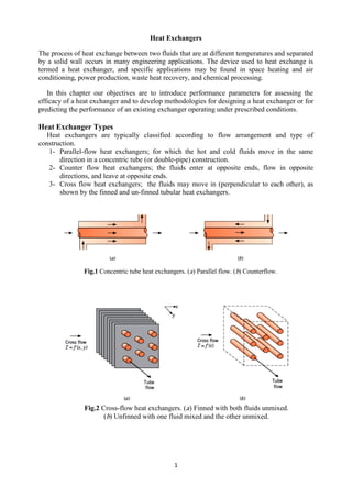
  • 1. 1 Heat Exchangers The process of heat exchange between two fluids that are at different temperatures and separated by a solid wall occurs in many engineering applications. The device used to heat exchange is termed a heat exchanger, and specific applications may be found in space heating and air conditioning, power production, waste heat recovery, and chemical processing. In this chapter our objectives are to introduce performance parameters for assessing the efficacy of a heat exchanger and to develop methodologies for designing a heat exchanger or for predicting the performance of an existing exchanger operating under prescribed conditions. Heat Exchanger Types Heat exchangers are typically classified according to flow arrangement and type of construction. 1- Parallel-flow heat exchangers; for which the hot and cold fluids move in the same direction in a concentric tube (or double-pipe) construction. 2- Counter flow heat exchangers; the fluids enter at opposite ends, flow in opposite directions, and leave at opposite ends. 3- Cross flow heat exchangers; the fluids may move in (perpendicular to each other), as shown by the finned and un-finned tubular heat exchangers. Fig.1 Concentric tube heat exchangers. (a) Parallel flow. (b) Counterflow. Fig.2 Cross-flow heat exchangers. (a) Finned with both fluids unmixed. (b) Unfinned with one fluid mixed and the other unmixed.
  • 2. 2 In Fig. 2a, the cross-flowing fluid is said to be unmixed because the fins inhibit motion in a direction (y). In this case the cross-flowing fluid temperature varies with x and y. In the finned exchanger both fluids are unmixed. In contrast, for the unfinned tube bundle of Fig. 2b, fluid motion, hence mixing, in the transverse direction is possible, and temperature variations are primarily in the main-flow direction. The cross-flowing fluid is mixed and the tube fluid is unmixed in the unfinned exchanger. 4- Shell and tube heat exchangers 5- Compact heat exchangers A special and important class of heat exchangers is used to achieve a very large heat transfer surface area per unit volume ( ≥ 400 m2 /m3 for liquids and ( ≥ 700 m2 /m3 for gases) Fig.3 Shell-and-tube heat exchanger with one shell pass and one tube pass. Fig.4 Shell-and-tube heat exchangers. (a) One shell pass and two tube passes. (b) Two shell passes and four tube passes.
  • 3. 3 Overall Heat Transfer Coefficient For a wall separating two fluid streams, the overall heat transfer coefficient may be expressed as ( ) ( ) ( ) Where, c and h refer to the cold and hot fluids, respectively. The deposition of a film or scale on the surface can greatly increase the resistance to heat transfer between the fluids. This effect can be treated by introducing an additional thermal resistance, termed the fouling factor, Rf. Its value depends on the operating temperature, fluid velocity, and length of service of the heat exchanger. For surface fouling and fin (extended surface) effects, the overall heat transfer coefficient is modified as follows: ( ) ( ) ( ) ( ) ( ) The quantity ηo is termed the overall surface efficiency or temperature effectiveness of a finned surface. It is defined such that, for the hot or cold surface without fouling, the heat transfer rate is ( ) Where, Tb is the base surface temperature, and A is the total (fin plus exposed base) surface area. Fig.5 Compact heat exchanger cores. Plate–fin (d) Single pass (e) Multipass Fin-tube
  • 4. 4 ( ) For the unfinned, tubular heat exchangers ( ) Where, subscripts i and o refer to inner and outer tube surfaces ( ), which may be exposed to either the hot or the cold fluid. Heat Exchanger Analysis: Use of the Log Mean Temperature Difference To design or to predict the performance of a heat exchanger, it is essential to relate the total heat transfer rate to quantities such as the inlet and outlet fluid temperatures, the overall heat transfer coefficient, and the total surface area for heat transfer. Applying overall energy balances to the hot and cold fluids. In particular, if q is the total rate of heat transfer between the hot and cold fluids and there is negligible heat transfer between the exchanger and its surroundings, the steady flow energy equation, gives ̇ ( ) ̇ ( ) Where, i is the fluid enthalpy. The subscripts h and c refer to the hot and cold fluids, whereas the subscripts i and o designate the fluid inlet and outlet conditions. If the fluids are not undergoing a phase change and constant specific heats are assumed, these expressions reduce to ̇ ( ) ̇ ( ) Where, ∆Tlm is an appropriate mean temperature difference. The Parallel-Flow Heat Exchanger The log mean temperature difference is Fig.6 Overall energy balances for the hot and cold fluids of a two-fluid heat exchanger. Fig.7 Temperature distributions for a parallel-flow heat exchanger.
  • 5. 5 ( ⁄ ) ( ⁄ ) For the parallel flow exchanger the temperature differences must now be defined as The Counterflow Heat Exchanger For the counter-flow exchanger the temperature differences must now be defined as Note that, for the same inlet and outlet temperatures, the log mean temperature difference for counter flow exceeds that for parallel flow, Tm,CF >Tm,PF. Hence the surface area required to effect a prescribed heat transfer rate q is smaller for the counter-flow than for the parallel-flow arrangement, assuming the same value of U. Also note that Tc,o can exceed Th,o for counter flow but not for parallel flow. Special Operating Conditions Fig.8 Temperature distributions for a counter-flow heat exchanger. Fig.9 Special heat exchanger conditions.
  • 6. 6 1- Condensation occurs at constant temperature, and, for all practical purposes, Ch→∞. For a heat exchanger in which the hot fluid has a heat capacity rate, ̇ which is much larger than that of the cold fluid, ̇ For this case the temperature of the hot fluid remains approximately constant throughout the heat exchanger, while the temperature of the cold fluid increases. 2- In an evaporator or a boiler, the cold fluid that experiences a change in phase and remains at a nearly uniform temperature (Cc→∞). 3- The third special case involves a counter-flow heat exchanger for which the heat capacity rates are equal (Ch = Cc). The temperature difference ∆T must then be constant throughout the exchanger, in which case ∆T1 =∆T2 =∆Tlm. EXAMPLE.1 A counter-flow, concentric tube heat exchanger is used to cool the lubricating oil for a large industrial gas turbine engine. The flow rate of cooling water through the inner tube (Di =25 mm) is 0.2 kg/s, while the flow rate of oil through the outer annulus (Do = 45 mm) is 0.1 kg/s. The oil and water enter at temperatures of 100 and 30o C, respectively. How long must the tube be made if the outlet temperature of the oil is to be 60o C? SOLUTION Known: Fluid flow rates and inlet temperatures for a counter-flow, concentric tube heat exchanger of prescribed inner and outer diameter. Find: Tube length to achieve a desired hot fluid outlet temperature. Schematic: Assumptions: 1. Negligible heat loss to the surroundings. 2. Negligible kinetic and potential energy changes. 3. Constant properties. 4. Negligible tube wall thermal resistance and fouling factors. 5. Fully developed conditions for the water and oil (U independent of x). Properties: unused engine oil (Th = 80o C = 353 K): cp= 2131 J/kg. K, µ = 3.25 x 10⁻² N. s/m2 , k = 0.138 W/m. K.Water (Tc =35o C): cp =4178 J/kg. K, µ = 725 x 10-6 N.s/m2 , k = 0.625 W/m. K, Pr = 4.85. Analysis: The required heat transfer rate may be obtained from the overall energy balance for the hot fluid. ̇ ( ) ( ) The water outlet temperature is ̇
  • 7. 7 The required heat exchanger length may now be obtained from ( ) ( ) ( ) ( ) ( ) The overall heat transfer coefficient is ( ) ( ) For water flow through the tube, ̇ ( ) ⁄ ( ) ( ) For the flow of oil through the annulus, the hydraulic diameter is, Dh = Do - Di = 0.02 m, and the Reynolds number is ( ) ( ) ̇ ( ) ( ) U = 38.1 W/m2 .K ( )( ) Heat Exchanger Analysis: The Effectiveness–NTU Method It is a simple matter to use the log mean temperature difference (LMTD) method of heat exchanger analysis when the fluid inlet temperatures are known and the outlet temperatures are specified or readily determined from the energy balance expressions. The value of ∆Tlm for the exchanger may then be determined. However, if only the inlet temperatures are known, use of the LMTD method requires a cumbersome iterative procedure. It is therefore preferable to employ an alternative approach termed the effectiveness–NTU (or NTU) method. Definitions To define the effectiveness of a heat exchanger, we must first determine the maximum possible heat transfer rate, qmax, for the exchanger. This heat transfer rate could, in principle, be achieved in a counter-flow heat exchanger of infinite length. The cold fluid would then experience the larger temperature change, and since L→∞, it would be heated to the inlet temperature of the hot fluid (Tc,o = Th,i). ( ) If Ch < Cc, the hot fluid would experience the larger temperature change and would be cooled to the inlet temperature of the cold fluid (Th,o= Tc,i). ( ) ( )
  • 8. 8 It is now logical to define the effectiveness, ε, as the ratio of the actual heat transfer rate for a heat exchanger to the maximum possible heat transfer rate: ( ) ( ) ( ) ( ) ( ) ( ) The number of transfer units (NTU) is a dimensionless parameter that is widely used for heat exchanger analysis and is defined as The heat capacity ratio Cr , is Cr = Cmin/Cmax
  • 9. 9 Fig.10 Effectiveness of a parallel flow heat exchanger. Fig.11 Effectiveness of a counter-flow heat exchanger.
  • 10. 10 Fig.12 Effectiveness of a shell-and tube heat exchanger with one shell and any multiple of two tube passes (two, four, etc. tube passes). Fig.13 Effectiveness of a shell-and tube heat exchanger with two shell passes and any multiple of four tube passes (four, eight, etc. tube passes) ( with n = 2). Fig.14 Effectiveness of a single pass, cross-flow heat exchanger with both fluids unmixed. Fig.15 Effectiveness of a single pass, cross-flow heat exchanger with one fluid mixed and the other unmixed.
  • 11. 11 EXAMPLE 2 Hot exhaust gases, which enter a finned-tube, cross-flow heat exchanger at 300o C and leave at 100o C, are used to heat pressurized water at a flow rate of 1 kg/s from 35 to 125o C. The overall heat transfer coefficient based on the gas-side surface area is Uh = 100 W/m2 . K. Determine the required gas-side surface area Ah using the NTU method. SOLUTION Known: Inlet and outlet temperatures of hot gases and water used in a finned-tube, cross flow heat exchanger. Water flow rate and gas-side overall heat transfer coefficient. Find: Required gas-side surface area. Schematic: Assumptions: 1. Negligible heat loss to the surroundings and kinetic and potential energy changes. 2. Constant properties. Properties: Water: Tc = 80 o C cp,c = 4197 J/kg. K. Analysis: The required surface area may be obtained from knowledge of the number of transfer units, which, in turn, may be obtained from knowledge of the ratio of heat capacity rates and the effectiveness. To determine the minimum heat capacity rate, we begin by computing. ̇ ̇ ( ) ̇ ( ) ̇ [ ] [ ] ( ) ( ) The actual heat transfer rate is ( ) ( ) Hence the effectiveness is
  • 12. 12 Heat Exchanger Design and Performance Calculations Two general types of heat exchanger problems are commonly encountered by the practicing engineer. In the heat exchanger design problem, the fluid inlet temperatures and flow rates, as well as a desired hot or cold fluid outlet temperature, are prescribed. The design problem is then one of specifying a specific heat exchanger type and determining its size—that is, the heat transfer surface area A—required to achieve the desired outlet temperature. In a heat exchanger performance calculation, an existing heat exchanger is analyzed to determine the heat transfer rate and the fluid outlet temperatures for prescribed flow rates and inlet temperatures. For heat exchanger design problems, the NTU method may be used by first calculating ε and (Cmin/Cmax). The appropriate equation (or chart) may then be used to obtain the NTU value, which in turn may be used to determine A. For a performance calculation, the NTU and (Cmin/Cmax) values may be computed and ε may then be determined from the appropriate equation (or chart) for a particular exchanger type. Since qmax may also be computed, it is a simple matter to determine the actual heat transfer rate from q = ε qmax. Both fluid outlet temperatures may then be determined.
  • 13. 13 Sheet 1- In a fire-tube boiler, hot products of combustion flowing through an array of thin-walled tubes are used to boil water flowing over the tubes. At the time of installation, the overall heat transfer coefficient was 400 W/m2 . K. After 1 year of use, the inner and outer tube surfaces are fouled, with corresponding fouling factors of Rƒ,i = 0.0015 and Rƒ,o= 0.0005 m2 . K/W, respectively. Should the boiler be scheduled for cleaning of the tube surfaces? 2- A type-302 stainless steel tube of inner and outer diameters Di = 22 mm and Do = 27 mm, respectively, is used in a cross-flow heat exchanger. The fouling factors, Rƒ, for the inner and outer surfaces are estimated to be 0.0004 and 0.0002 m2 . K/W, respectively. Determine the overall heat transfer coefficient based on the outside area of the tube, Uo. 3- A finned-tube, cross-flow heat exchanger is to use the exhaust of a gas turbine to heat pressurized water. Laboratory measurements are performed on a prototype version of the exchanger, which has a surface area of 10m2 , to determine the overall heat transfer coefficient as a function of operating conditions. Measurements made under particular conditions, for which ̇ = 2 kg/s, Th,i = 325 o C, ̇ = 0.5 kg/s, and Tc,i = 25o C, reveal a water outlet temperature of Tc,o = 150 o C. What is the overall heat transfer coefficient of the exchanger? 4- A process fluid having a specific heat of 3500 J/kg .K and flowing at 2 kg/s is to be cooled from 80o C to 50o C with chilled water, which is supplied at a temperature of 15o C and a flow rate of 2.5 kg/s. Assuming an overall heat transfer coefficient of 2000 W/m2 . K, calculate the required heat transfer areas for the following (a) parallel flow, (b) counter flow, (c) shell-and-tube, one shell pass and two tube passes, and (d) cross- flow, single pass, both fluids unmixed. 5- A shell-and-tube exchanger (two shells, four tube passes) is used to heat 10,000 kg/h of pressurized water from 35 to 120o C with 5000 kg/h pressurized water entering the exchanger at 300 o C. If the overall heat transfer coefficient is 1500 W/m2 . K, determine the required heat exchanger area. 6- The hot and cold inlet temperatures to a concentric tube heat exchanger are Th,i = 200 o C, Tc,i = 100 o C, respectively. The outlet temperatures are Th,o = 110 o C and Tc,o = 125 o C. Is the heat exchanger operating in a parallel flow or in a counter flow configuration? What is the heat exchanger effectiveness? What is the NTU? Phase change does not occur in either fluid. 7- A counter flow, concentric tube heat exchanger is designed to heat water from 20 to 80 o C using hot oil, which is supplied to the annulus at 160 o C and discharged at 140 o C. The thin-walled inner tube has a diameter of Di = 20 mm, and the overall heat transfer
  • 14. 14 coefficient is 500 W/m2 . K. The design condition calls for a total heat transfer rate of 3000 W. (a) What is the length of the heat exchanger? (b) After 3 years of operation, performance is degraded by fouling on the water side of the exchanger, and the water outlet temperature is only 65 o C for the same fluid flow rates and inlet temperatures. What are the corresponding values of the heat transfer rate, the outlet temperature of the oil, the overall heat transfer coefficient, and the water-side fouling factor ? 8- A shell-and-tube heat exchanger must be designed to heat 2.5 kg/s of water from 15 to 85o C. The heating is to be accomplished by passing hot engine oil, which is available at 160o C, through the shell side of the exchanger. The oil is known to provide an average convection coefficient of ho = 400 W/m2 .K on the outside of the tubes. Ten tubes pass the water through the shell. Each tube is thin walled, of diameter D = 25 mm, and makes eight passes through the shell. If the oil leaves the exchanger at 100o C, what is its flow rate? How long must the tubes be to accomplish the desired heating? 9- A single-pass, cross-flow heat exchanger uses hot exhaust gases (mixed) to heat water (unmixed) from 30 to 80 o C at a rate of 3 kg/s. The exhaust gases, having thermophysical properties similar to air, enter and exit the exchanger at 225 and 100 o C, respectively. If the overall heat transfer coefficient is 200 W/m2 . K, estimate the required surface area. 10- Saturated water vapor leaves a steam turbine at a flow rate of 1.5 kg/s and a pressure of 0.51 bar. The vapor is to be completely condensed to saturated liquid in a shell-and-tube heat exchanger that uses city water as the cold fluid. The water enters the thin-walled tubes at 17 o C and is to leave at 57o C. Assuming an overall heat transfer coefficient of 2000 W/m2 _ K, determine the required heat exchanger surface area and the water flow rate. After extended operation, fouling causes the overall heat transfer coefficient to decrease to 1000 W/m2 . K, and to completely condense the vapor, there must be an attendant reduction in the vapor flow rate. For the same water inlet temperature and flow rate, what is the new vapor flow rate required for complete condensation? 11- A two-fluid heat exchanger has inlet and outlet temperatures of 65 and 40 o C for the hot fluid and 15 and 30 o C for the cold fluid. Can you tell whether this exchanger is operating under counter flow or parallel flow conditions? Determine the effectiveness of the heat exchanger. 12- Saturated steam at 110 o C is condensed in a shell-and tube heat exchanger (1 shell pass; 2, 4, . . . tube passes) with a UA value of 2.5 kW/K. Cooling water enters at 40 o C. (a) Calculate the cooling water flow rate required to maintain a heat rate of 150 kW. (b) Assuming that UA is independent of flow rate, calculate and plot the water flow rate required to provide heat rates over the range from 130 to 160 kW. Comment on the validity of your assumption. 13- A shell-and-tube heat exchanger (1 shell pass, 2 tube passes) is to be used to condense 2.73 kg/s of saturated steam at 340 K. Condensation occurs on the outer tube surfaces, and the corresponding convection coefficient is 10,000 W/m2 .K. The temperature of the cooling water entering the tubes is 15 o C, and the exit temperature is not to exceed 30 o C. Thin-walled tubes of 19-mm diameter are specified, and the mean velocity of water flow through the tubes is to be maintained at 0.5 m/s. (a) What is the minimum number of tubes that should be used, and what is the corresponding tube length per pass? (b) To reduce the size of the heat exchanger, it is proposed to increase the water-side convection coefficient by inserting a wire mesh in the tubes. If the mesh increases the convection coefficient by a factor of two, what is the required tube length per pass?
  • 15. 15 14- The oil in an engine is cooled by air in a cross-flow heat exchanger where both fluids are unmixed. Atmospheric air enters at 30 o C and 0.53 kg/s. Oil at 0.026 kg/s enters at 75 o C and flows through a tube of 10-mm diameter. Assuming fully developed flow and constant wall heat flux, estimate the oil-side heat transfer coefficient. If the overall convection coefficient is 53 W/m2 . K and the total heat transfer area is 1m2 , determine the effectiveness. What is the exit temperature of the oil? 15- A concentric tube heat exchanger uses water, which is available at 15 o C, to cool ethylene glycol from 100 to 60 o C. The water and glycol flow rates are each 0.5 kg/s. What are the maximum possible heat transfer rate and effectiveness of the exchanger? Which is preferred, a parallel-flow or counter flow mode of operation? 16- Hot exhaust gases are used in a shell-and-tube exchanger to heat 2.5 kg/s of water from 35 to 85 o C. The gases, assumed to have the properties of air, enter at 200 o C and leave at 93 o C. The overall heat transfer coefficient is 180 W/m2 . K. Using the effectiveness– NTU method, calculate the area of the heat exchanger.