1. Solution 2.3-8 Bar with a hole
80 CHAPTER 2 Axially Loaded Numbers
d2
d1
L
4
P P
— L
4
— L
2
—
d
d diameter of hole
SHORTENING OF THE BAR
(Eq. 1)
NUMERICAL VALUES (DATA):
maximum allowable shortening of the bar
8.0 mm
PL
E
¢
1
d1
2
d2
1
d1
2
2
d2
2 ≤
P
EC
L4
4
(d1
2
d2
)
L4
4
d1
2
L2
4
d2
2
S
a
Ni Li
Ei Ai
P
E a
Li
Ai
P 110 kN L 1.2 m E 4.0 GPa
d1 100 mm
dmax maximum allowable diameter of the hole
d2 60 mm
SUBSTITUTE NUMERICAL VALUES INTO EQ. (1) FOR
AND SOLVE FOR d dmax:
UNITS: Newtons and meters
dmax 23.9 mm —
d 0.02387 m
d2
569.81 106
m2
761.598 100 555.556 106.042
1
0.01 d2
761.598
1
0.01 d2
1
0.01
2
0.0036
B
1
(0.1)2
d2
1
(0.1)2
2
(0.06)2 R
0.008
(110,000)(1.2)
(4.0 109
)
Problem 2.3-9 A wood pile, driven into the earth, supports a load P entirely
by friction along its sides (see figure). The friction force f per unit length of pile
is assumed to be uniformly distributed over the surface of the pile. The pile has
length L, cross-sectional area A, and modulus of elasticity E.
(a) Derive a formula for the shortening of the pile in terms of P, L, E,
and A.
(b) Draw a diagram showing how the compressive stress c varies throughout
the length of the pile.
L
P
f
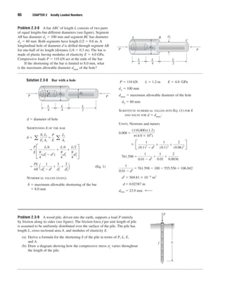
Problem 2.3-8 A bar ABC of length L consists of two parts
of equal lengths but different diameters (see figure). Segment
AB has diameter d1 100 mm and segment BC has diameter
d2 60 mm. Both segments have length L/2 0.6 m. A
longitudinal hole of diameter d is drilled through segment AB
for one-half of its length (distance L/4 0.3 m). The bar is
made of plastic having modulus of elasticity E 4.0 GPa.
Compressive loads P 110 kN act at the ends of the bar.
If the shortening of the bar is limited to 8.0 mm, what
is the maximum allowable diameter dmax of the hole?
d2
d1
L
4
P P
A B
C
— L
4
— L
2
—
3. Problem 2.3-11 A flat bar of rectangular cross section, length
L, and constant thickness t is subjected to tension by forces
P (see figure). The width of the bar varies linearly from b1 at
the smaller end to b2 at the larger end. Assume that the angle
of taper is small.
(a) Derive the following formula for the elongation of the
bar:
Et(b
P
2
L
b1)
ln
b
b
2
1
(b) Calculate the elongation, assuming L 5 ft, t 1.0 in.,
P 25 k, b1 4.0 in., b2 6.0 in., and E 30 106 psi.
82 CHAPTER 2 Axially Loaded Numbers
P
P
t
b1
b2
L
Solution 2.3-11 Tapered bar (rectangular cross section)
P
dx
x
P
L0 L
0 b1 b b2
t thickness (constant)
(Eq. 1)
(a) ELONGATION OF THE BAR
(Eq. 2)
PL0
Eb1t
lnx L0
L0L
PL0
Eb1t
ln
L0 L
L0
L0L
L0
d
PL0
Eb1t
L0L
L0
dx
x
d
Pdx
EA(x)
PL0 dx
Eb1tx
A(x) bt b1t ¢
x
L0
≤
b b1¢
x
L0
≤b2 b1¢
L0 L
L0
≤
(Eq. 3)
(Eq. 4)
Substitute Eqs. (3) and (4) into Eq. (2):
(Eq. 5)
(b) SUBSTITUTE NUMERICAL VALUES:
L 5 ft 60 in. t 10 in.
P 25 k b1 4.0 in.
b2 6.0 in. E 30 106 psi
From Eq. (5): 0.010 in. —
PL
Et(b2 b1)
ln
b2
b1
—
Solve Eq. (3) for L0: L0 L ¢
b1
b2 b1
≤
From Eq. (1):
L0 L
L0
b2
b1
4. Problem 2.3-12 A post AB supporting equipment in a laboratory is
tapered uniformly throughout its height H (see figure). The cross
sections of the post are square, with dimensions b b at the top
and 1.5b 1.5b at the base.
Derive a formula for the shortening of the post due to the
compressive load P acting at the top. (Assume that the angle of
taper is small and disregard the weight of the post itself.)
Solution 2.3-12 Tapered post
SECTION 2.3 Changes in Lengths under Nonuniform Conditions 83
H
P
A
B
A b
b
B 1.5b
1.5b
Square cross sections
b width at A
1.5b width at B
by width at distance y
Ay cross-sectional area at distance y
(by)2
b2
H2 (H 0.5y)2
b
H
(H 0.5y)
b (1.5b b)
y
H
SHORTENING OF ELEMENT dy
SHORTENING OF ENTIRE POST
2PH
3Eb2 —
PH2
Eb2 B
1
(0.5)(1.5H)
1
0.5H
R
PH2
Eb2 B
1
(0.5)(H 0.5y)
R
0
H
From Appendix C:
dx
(a bx)2
1
b(a bx)
d
PH2
Eb2
H
0
dy
(H 0.5y)2
d
Pdy
EAy
Pdy
E ¢
b2
H2
≤ (H 0.5y)2
P
A
B
y
dy
b
by
1.5 b
H
5. Problem 2.3-13 A long, slender bar in the shape of a right circular cone
with length L and base diameter d hangs vertically under the action of its
own weight (see figure). The weight of the cone is W and the modulus of
elasticity of the material is E.
Derive a formula for the increase in the length of the bar due to
its own weight. (Assume that the angle of taper of the cone is small.)
Solution 2.3-13 Conical bar hanging vertically
84 CHAPTER 2 Axially Loaded Numbers
d
L
ELEMENT OF BAR
Wweight of cone
ELONGATION OF ELEMENT dy
ELONGATION OF CONICAL BAR
d
4W
d2
EL
L
0
y dy
2WL
d
2
E
—
d
Ny dy
E Ay
Wy dy
E ABL
4W
d2
EL
y dy
d
y
L
dy
dy
Ny
Ny
TERMINOLOGY
Ny axial force acting on element dy
Ay cross-sectional area at element dy
AB cross-sectional area at base of cone
V volume of cone
Vy volume of cone below element dy
Wy weight of cone below element dy
Ny Wy
Vy
V
(W)
AyyW
ABL
1
3
Ay y
1
3
AB L
d2
4
6. Problem 2.3-14 A bar ABC revolves in a horizontal plane about a
vertical axis at the midpoint C (see figure). The bar, which has length
2L and cross-sectional area A, revolves at constant angular speed .
Each half of the bar (AC and BC) has weight W1 and supports a weight
W2 at its end.
Derive the following formula for the elongation of one-half of the
bar (that is, the elongation of either AC or BC):
3
L
g
2
E
A
2
(W1 3W2)
in which E is the modulus of elasticity of the material of the bar and
g is the acceleration of gravity.
Solution 2.3-14 Rotating bar
SECTION 2.3 Changes in Lengths under Nonuniform Conditions 85
A C B
L L
W2 W1 W1 W2
C
B
L
W1 W2
x
F(x)
dx
d
angular speed
A cross-sectional area
E modulus of elasticity
g acceleration of gravity
F(x) axial force in bar at distance x from point C
Consider an element of length dx at distance x from
point C.
To find the force F(x) acting on this element, we
must find the inertia force of the part of the bar from
distance x to distance L, plus the inertia force of the
weight W2.
Since the inertia force varies with distance from
point C, we now must consider an element of
length d at distance , where varies from x to L.
Acceleration of element 2
Centrifugal force produced by element
(mass)(acceleration)
W12
gL
jdj
Mass of element dj
dj
L
¢
W1
g
≤
Centrifugal force produced by weight W2
AXIAL FORCE F(x)
ELONGATION OF BAR BC
L2
2
3gEA
(W1 3W2) —
W1L2
2
3gEA
W2L2
2
gEA
W2L2
gEA
L
0
dx
W12
2gLEA
B
L
0
L2
dx
L
0
x2
dxR
L
0
W12
2gLEA
(L2
x2
)dx
L
0
W2L2
dx
gEA
L
0
F(x) dx
EA
W12
2gL
(L2
x2
)
W2L2
g
F(x)
jL
jx
W12
gL
jdj
W2L2
g
¢
W2
g
≤(L2
)
9. Statically Indeterminate Structures
Problem 2.4-1 The assembly shown in the figure consists of a brass
core (diameter d1 0.25 in.) surrounded by a steel shell (inner diameter
d2 0.28 in., outer diameter d3 0.35 in.). A load P compresses the
core and shell, which have length L 4.0 in. The moduli of elasticity
of the brass and steel are Eb 15 106 psi and Es 30 106 psi,
respectively.
(a) What load P will compress the assembly by 0.003 in.?
(b) If the allowable stress in the steel is 22 ksi and the allowable
stress in the brass is 16 ksi, what is the allowable compressive
load Pallow? (Suggestion: Use the equations derived in
Example 2-5.)
Solution 2.4-1 Cylindrical assembly in compression
88 CHAPTER 2 Axially Loaded Numbers
P
Steel shell
Brass core
d3
d1
d2
L
P
Steel shell
Brass core
d3
d1
d2
L
d1 0.25 in. Eb15 106 psi
d2 0.28 in. Es30 106 psi
(a) DECREASE IN LENGTH ( 0.003 in.)
Use Eq. (2-13) of Example 2-5.
P (Es As Eb Ab)¢
L
≤
PL
Es As Eb Ab
or
L 4.0 in.Ab
4
d1
2
0.04909 in.2
d3 0.35 in.As
4
(d3
2
d2
2
) 0.03464 in.2
Substitute numerical values:
(b) Allowable load
s22 ksi b16 ksi
Use Eqs. (2-12a and b) of Example 2-5.
For steel:
For brass:
Steel governs.Pallow 1300 lb —
Ps (1.776 106
lb)¢
16 ksi
15 106
psi
≤ 1890 lb
sb
PEb
Es As Eb Ab
Ps (Es As Eb Ab)
sb
Eb
Ps (1.776 106
lb)¢
22 ksi
30 106
psi
≤ 1300 lb
ss
PEs
Es As Eb Ab
Ps (Es As Eb Ab)
ss
Es
1330 lb —
P (1.776 106
lb)¢
0.003 in.
4.0 in.
≤
1.776 106
lb
(15 106
psi)(0.04909 in.2
)
Es As Eb Ab (30 106
psi)(0.03464 in.2
)
10. Problem 2.4-2 A cylindrical assembly consisting of a brass core and
an aluminum collar is compressed by a load P (see figure). The length
of the aluminum collar and brass core is 350 mm, the diameter of the
core is 25 mm, and the outside diameter of the collar is 40 mm. Also, the
moduli of elasticity of the aluminum and brass are 72 GPa and 100 GPa,
respectively.
(a) If the length of the assembly decreases by 0.1% when the load
P is applied, what is the magnitude of the load?
(b) What is the maximum permissible load Pmax if the allowable
stresses in the aluminum and brass are 80 MPa and 120 MPa,
respectively? (Suggestion: Use the equations derived in
Example 2-5.)
Solution 2.4-2 Cylindrical assembly in compression
SECTION 2.4 Statically Indeterminate Structures 89
Aluminum collar
Brass core
25 mm
40 mm
P
350 mm
A
B
db
da
P
350 mm
A aluminum
B brass
L 350 mm
da 40 mm
db 25 mm
765.8 mm2
(a) DECREASE IN LENGTH
( 0.1% of L 0.350 mm)
Use Eq. (2-13) of Example 2-5.
490.9 mm2
Ea 72 GPaEb 100 GPaAb
4
db
2
Aa
4
(da
2
db
2
)
Substitute numerical values:
EaAa EbAb (72 GPa)(765.8 mm2)
(100 GPa)(490.9 mm2)
55.135 MN 49.090 MN
104.23 MN
(b) ALLOWABLE LOAD
A 80 MPa b 120 MPa
Use Eqs. (2-12a and b) of Example 2-5.
For aluminum:
For brass:
Aluminum governs.Pmax 116 kN
Pb (104.23 MN)¢
120 MPa
100 GPa
≤ 125.1 kN
sb
PEb
Ea Aa Eb Ab
Pb (Ea Aa Eb Ab)¢
sb
Eb
≤
Pa (104.23 MN)¢
80 MPa
72 GPa
≤ 115.8 kN
sa
PEa
Ea Aa EbAb
Pa (Ea Aa EbAb)¢
sa
Ea
≤
104.2 kN —
P (104 23 MN)¢
0.350 mm
350 mm
≤
P (Ea Aa Eb Ab)¢
L
≤
PL
Ea Aa EbAb
or
14. Problem 2.4-6 A plastic rod AB of length L 0.5 m has a
diameter d1 30 mm (see figure). A plastic sleeve CD of length
c 0.3 m and outer diameter d2 45 mm is securely bonded
to the rod so that no slippage can occur between the rod and the
sleeve. The rod is made of an acrylic with modulus of elasticity
E1 3.1 GPa and the sleeve is made of a polyamide with
E2 2.5 GPa.
(a) Calculate the elongation of the rod when it is pulled by
axial forces P 12 kN.
(b) If the sleeve is extended for the full length of the rod,
what is the elongation?
(c) If the sleeve is removed, what is the elongation?
Solution 2.4-6 Plastic rod with sleeve
SECTION 2.4 Statically Indeterminate Structures 93
L
c b
b
P P
A B
C D
d1 d2
L
c b
b
P P
A B
C D
d1 d1
d2
P 12 kN d1 30 mm b 100 mm
L 500 mm d2 45 mm c 300 mm
Rod: E1 3.1 GPa
Sleeve: E2 2.5 GPa
E1A1 E2A2 4.400 MN
(a) ELONGATION OF ROD
(From Eq. 2-13 of Example 2-5)
2AC CD 1.91 mm —
0.81815 mm
Part CD: CD
Pc
E1A1E2A2
Part AC: AC
Pb
E1A1
0.5476 mm
Sleeve: A2
4
(d2
2
d1
2
) 883.57 mm2
Rod: A1
d1
2
4
706.86 mm2
(b) SLEEVE AT FULL LENGTH
(c) SLEEVE REMOVED
PL
E1A1
2.74 mm —
1.36 mm —
CD ¢
L
C
≤ (0.81815 mm) ¢
500 mm
300 mm
≤
24. Problem 2.4-16 A trimetallic bar is uniformly compressed by an
axial force P 40 kN applied through a rigid end plate (see figure).
The bar consists of a circular steel core surrounded by brass and cop-
per tubes. The steel core has diameter 30 mm, the brass tube has outer
diameter 45 mm, and the copper tube has outer diameter 60 mm. The
corresponding moduli of elasticity are Es 210 GPa, Eb 100 GPa,
and Ec 120 GPa.
Calculate the compressive stresses s, b, and c in the steel, brass,
and copper, respectively, due to the force P.
SECTION 2.4 Statically Indeterminate Structures 103
FORCE-DISPLACEMENT RELATIONS
(Eqs. 3, 4)
SOLUTION OF EQUATIONS
Substitute (3) and (4) into Eq. (2):
(Eq. 5)
TENSILE FORCES IN THE WIRES
Solve simultaneously Eqs. (1) and (5):
(Eqs. 6, 7)
TENSILE STRESSES IN THE WIRES
(Eq. 8)
(Eq. 9)
sD
TD
A
dPL
A(2c2
d2
)
sc
Tc
A
2cPL
A(2c2
d2
)
Tc
2cPL
2c2
d2TD
dPL
2c2
d2
Tch
cEA
TD(2h)
dEA
or
Tc
c
2TD
d
c
Tch
EA
D
TD(2h)
EA
DISPLACEMENT AT END OF BAR
(Eq. 10)
SUBSTITUTE NUMERICAL VALUES
(a)
(b)
0.0198 in. —
2(18 in.)(340 lb)(66 in.)2
(30 106
psi)(0.0272 in.2
)(3300 in.2
)
B
2hPL2
EA(2c2
d2
)
12,500 psi —
sD
dPL
A(2c2
d2
)
(50 in.)(340 lb)(66 in.)
(0.0272 in.2
)(3300 in.2
)
10,000 psi —
sc
2cPL
A(2c2
d2
)
2(20 in.)(340 lb)(66 in.)
(0.0272 in.2
)(3300 in.2
)
2c2
d2
2(20 in.)2
(50 in.)2
3300 in.2
B D ¢
L
d
≤
2hTD
EA
¢
L
d
≤
2hPL2
EA(2c2
d2
)
P = 40 kN
Copper tube Brass tube
Steel core
30
mm
45
mm
60
mm
26. Thermal Effects
Problem 2.5-1 The rails of a railroad track are welded together at their
ends (to form continuous rails and thus eliminate the clacking sound of
the wheels) when the temperature is 60°F.
What compressive stress is produced in the rails when they
are heated by the sun to 120°F if the coefficient of thermal expansion
6.5 106/°F and the modulus of elasticity E 30 106 psi?
Solution 2.5-1 Expansion of railroad rails
SECTION 2.5 Thermal Effects 105
The rails are prevented from expanding because of
their great length and lack of expansion joints.
Therefore, each rail is in the same condition as a bar
with fixed ends (see Example 2-7).
The compressive stress in the rails may be calculated
from Eq. (2-18).
s 11,700 psi —
(30 106
psi)(6.5 106
F)(60F)
s E
(¢T)
¢T 120F 60F 60F
Problem 2.5-2 An aluminum pipe has a length of 60 m at a temperature
of 10°C. An adjacent steel pipe at the same temperature is 5 mm longer
than the aluminum pipe.
At what temperature (degrees Celsius) will the aluminum pipe
be 15 mm longer than the steel pipe? (Assume that the coefficients
of thermal expansion of aluminum and steel are
a 23 106/°C
and
s 12 106/°C, respectively.)
Solution 2.5-2 Aluminum and steel pipes
INITIAL CONDITIONS
La 60 m T0 10C
Ls 60.005 m T0 10C
a 23 106/C
s 12 106/C
FINAL CONDITIONS
Aluminum pipe is longer than the steel pipe by the
amount L 15 mm.
T increase in temperature
a
a(T)La s
s(T)Ls
From the figure above:
a La L s Ls
or,
a(T)La La L
s(T)Ls Ls
Solve for T:
Substitute numerical values:
a La
s Ls 659.9 106 m/C
40.3C —
T T0 ¢T 10C 30.31C
¢T
15 mm 5 mm
659.9 106
mC
30.31C
¢T
¢L (Ls La)
a La
s Ls
—
a La
L s Ls
Aluminum pipe
Steel pipe