2. Station: Omitted
Project Number: Omitted
Calculation Number: Omitted
Page 2 of 3
Title: Omitted
1.0 Background
This proposed design installs two three phase pad mounted reclosers to provide secondary protection for the 6MVA
13.8/13.2kV site power transformers 0X03 and 0X04 and to mitigate the impact on the balance of plant equipment
due to a fault in the plant site power system. A recent ground fault on the secondary side of one of the transformers
has demonstrated that the transformers are not adequately protected (i.e. the transformer damage occurred). The
reclosers will be located between the secondary side of transformers 0X03 and 0X04 and the first downstream pad
mounted switches 0DISC289-SW17 and 0DISC289-SW16. As most of the distribution system cabling is
underground, the new reclosers will be set to interrupt and will not reclose (i.e. one shot protection scheme).
Transformers 0X03 and 0X04 are powered by 13.8kV buses 11 (breaker 252-1106) and 21 (252-2106) respectively.
These transformers then go on to feed disconnect switches 0DISC289-17 and 0DISC289-16 respectively.
The purpose of this study is to develop the new recloser controller phase and ground protection settings to ensure
that the transformers are adequately protected and that coordination exists between the reclosers, the upstream
feeder breakers, and downstream fuses.
2.0 Design Input
The maximum interrupting rating of the reclosers is 12kA (Reference OMITTED). This is greater than the
maximum short circuit on the system of approximately 4.85kA. The maximum short circuit current was calculated
based on the transformer impedance of 6.5% (Reference OMITTED), cable A0H206P impedance (Reference
OMITTED), and a conservative assumption that a 6MVA load is connected with 50% of the load being motor load
drawing 650% locked rotor current. The ETAP model generated for coordination purposes was used to calculate this
value. It should be noted that negative sequence impedance data is not available for transformers 0X03 and 0X04
and therefore the fault current for ground faults is conservatively assumed to be the same as for phase faults.
Ground and phase protection is provided for the primary side of transformers 0X03 and 0X04 from SEL-551 relays
which control breakers 252-1106 and 252-2106. Downstream of disconnect switches 0DISC289-17 and 0DISC289-
16 are fused disconnect switches 0DISC289-SW01 and 0DISC289-SW14 respectively which each contain a
Combined Technologies Type 155F125-Q1B fuse (Reference OMITTED). It should be noted that based on vendor
input, the TCC curve for this fuse is the same as the TCC curve for a Cooper X-Limiter type fuse. The TCC curves
for the fuses are provided in (Reference OMITTED). The TCC curves for the SEL-551 relay are shown in
(Reference OMITTED). The ETAP library is utilized to model these devices. The TCC curves for the Form 6
recloser controls are shown in (Reference OMITTED). Note that the ETAP library does not contain a Form 6
controller but it does contain a Form 4C controller. Review of the Cooper vendor literature indicates that the TCC
curves of the Form 4C are the same as the Form 6 controller. Therefore the Form 4C controller will be utilized in the
ETAP model. The existing settings for the SEL-551 relay are documented in (Reference OMITTED). Damage
curves were not available for transformers 0X03 and 0X04 and therefore, a typical damage curve was selected using
ANSI C57.109 and based on the transformer ratings from (Reference OMITTED). It was assumed that the total
connected transformer load downstream of transformers 0X03 and 0X04 is 6MVA. Typical inrush current for liquid
filled 13kV transformers is 12 times the full load current at 6 cycles. This value is reflected in Attachment 1. The
damage curve for the 500MCM cables is taken from the NEC.
3.0 Analysis
The recloser phase and ground protection settings were selected such that the transformers are protected and they
coordinate with the downstream fuses and upstream SEL-551 relay. For the phase protection, curve 202 was
selected and a pickup of 300A was selected. Also a minimum response time TCC modifier of 15cycle and a vertical
multiplier of 0.37 were selected. The resultant curve shape allows for coordination between the fuse and the Form 6
3. Station: Omitted
Project Number: Omitted
Calculation Number: Omitted
Page 3 of 3
Title: Omitted
recloser controller. For ground protection, curve 202 was also selected and a pickup of 250A was selected. No TCC
modifiers were used. The resultant curve shape allows for coordination between the fuse and the Form 6 recloser
controller. It should be noted that although actual ground fault current is not known, transformers 0X03 and 0X04
are still adequately protected. Ground faults lower than 250A will not damage the transformers as this is less than
their full load current rating. The Form 6 settings for each recloser are documented in Attachment 2.
4.0 Results/Conclusions
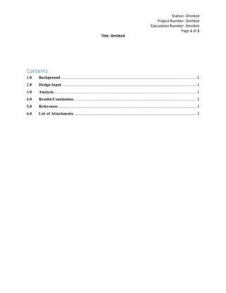
A coordination plot was created using the above methodology as well as the input discussed in Section 2.0 and is
attached to this document as Attachment 1. As the transformers 0X03 and 0X04 are all delta-wye connected, the
ground protection on the primary side of 0X03 and 0X04 will not see ground faults on the secondary side. As such,
coordination for the ground TCC curves between the recloser and SEL-551 relay is not required. The phase
protection provided by the SEL-551 relay, however, will need to coordinate with the ground protection provided by
the recloser controller. For ground faults on the secondary side of transformers 0X03 and 0X04, the phase protection
of the SEL-551 relays will see 58% (i.e. 1/√3) of the fault current times the transformer turns ratio (i.e. 58% *
13.2kV/13.8kV = 55.5%). This shift was not plotted in Attachment 1. A visual inspection of Attachment 1 was
performed and it was determined that the recloser ground protection coordinates with the SEL-551 phase protection.
Since this is the case, as can be seen in Attachment 1, proper coordination exists up to the calculated maximum short
circuit value and the transformers and cables will be protected using the selected recloser settings. This allows for
improved protection of transformers 0X03 and 0X04 as well as mitigation of impacts on the auxiliary power system
due to system faults.
5.0 References
OMITTED
6.0 List of Attachments*
6.1 Attachment 1: Coordination Plot XXXX
6.2 Attachment 2: Cooper Form 6 Controller Settings Sheet
*Other Attachments OMITTED
4. 0DISC289-SW16/SW17 Fuse
Cooper
X-Limiter
Coordinating 15.5 kV
125A
SEL-551 - P
OC1
Schweitzer
551
CT Ratio 1200:5
U3 - U.S. Very Inverse
Pickup = 1.5 (0.5 - 16 Sec - 5A)
Time Dial = 5
3x = 2.91 s, 5x = 1.29 s, 8x = 0.789 s
Inst = 24 (0.5 - 80 Sec - 5A)
A0H206P
1 - 3/C 500 kcmil
Aluminum Rubber
Tc = 90C
0X03/0X04
6 MVA (Secondary) 6.5 %Z
Delta-Wye Solid Grd
ANSI Curve Shift = 0.58
Inrush
FLA
Recloser - P
TCC1
Cooper
Form 4C
202
Pickup = 300 (100 - 2400 Primary)
Interrupting Time = 34 ms
Minimum Response Time = 15 Cycles
Vertical Multiplier = 0.37
3x = 3.72 s, 5x = 1.21 s, 8x = 0.495 s
Clearing
Recloser - 3P
4.851kA @ 13.2kV
(Sym)
SEL-551 - G
OC1
Schweitzer
551
CT Ratio 50:5
U2 - U.S. Inverse
Pickup = 1.4 (0.5 - 16 Sec - 5A)
Time Dial = 1
3x = 0.924 s, 5x = 0.428 s, 8x = 0.274 s
Recloser - G
TCC1
Cooper
Form 4C
202
Pickup = 250 (2 - 400 Primary)
Interrupting Time = 34 ms
3x = 10 s, 5x = 3.22 s, 8x = 1.28 s
Clearing
10K.5 1 10 100 1K3 5 30 50 300 500 3K 5K
Amps X 10 Site Power (Nom. kV=13.2, Plot Ref. kV=13.2)
10K.5 1 10 100 1K3 5 30 50 300 500 3K 5K
Amps X 10 Site Power (Nom. kV=13.2, Plot Ref. kV=13.2)
1K
.01
.1
1
10
100
.03
.05
.3
.5
3
5
30
50
300
500
Seconds 1K
.01
.1
1
10
100
.03
.05
.3
.5
3
5
30
50
300
500
Seconds
ETAP Star 7.1.0N
Site Power Coordination
Project: Site Self Power Reclosers
Location: CCNPP
Contract:
Engineer: Sargent & Lundy, LLC
Filename: D:0n7518ConstellationCalvert Cliffs11562-08011562-080 Coordination115
Date: 09-17-2012
SN: SARGENTLDY
Rev: Base
Fault: Ground
o
o
Bus 11/21
Site Power
79 Recloser
0DISC289-SW16/SW17 Fuse
OCR SEL-551
252-1106/2106
0X03/0X04
6 MVA
A0H206P
1-3/C 500
Site Power Loads
6 MVA
Site Power
252-1106/2106
Site Power Loads
6 MVA
A0H206P
1-3/C 500
SEL-551
0X03/0X04
6 MVA
Recloser
0DISC289-SW16/SW17 Fuse
Bus 11/21
ECP-12-000556
Form 7, Attachment 2
Page 1 of 1
Note: SEL-551 phase protection will only see 58% times the transformer turns ratio of a ground fault on the secondary side of the transformer due to
its delta-wye connection. Therefore, although not shown on this plot, coordination exists between the SEL-551-P and Recloser-G curves.
1
5. Page 1
Device Identity
0BKR252-0H1106UserDeviceName
Alternate 3Alternate 2Alternate 1NormalOvercurrent Settings
Phase:
UnblockedUnblockedUnblockedUnblockedPhsTripBlk
UnblockedUnblockedUnblockedUnblockedFastTripBlock
300300300300TCCPMinTrip
IEC EI (202)IEC EI (202)IEC EI (202)IEC EI (202)TCC1PCurve
EnableEnableEnableEnableTCC1PMultEnable
0.370.370.370.37TCC1PMult
DisableDisableDisableDisableTCC1PAddEnable
0000TCC1PAdd
EnableEnableEnableEnableTCC1PMRTAEnable
0.250.250.250.25TCC1PMRTA
DisableDisableDisableDisableTCC1PHCTEnable
32323232TCC1PHCT Mul
0.0160.0160.0160.016TCC1PHCTDly
IEC EI (202)IEC EI (202)IEC EI (202)IEC EI (202)TCC2PCurve
EnableEnableEnableEnableTCC2PMultEnable
0.370.370.370.37TCC2PMult
DisableDisableDisableDisableTCC2PAddEnable
0000TCC2PAdd
EnableEnableEnableEnableTCC2PMRTAEnable
0.250.250.250.25TCC2PMRTA
DisableDisableDisableDisableTCC2PHCTEnable
32323232TCC2PHCT Mul
0.0160.0160.0160.016TCC2PHCTDly
Doc ID: 0BKR252-0H1106/RECL, Rev. 0
Doc Type: PRSS
ECP: ECP-12-000556
Attachment 2
Page 1 of 11
/RECL
*
*
*
*
*
*
*
*
*
*
* Indicates Significant Functional Setting