

Recommended
More Related Content
What's hot
What's hot (20)
Similar to Medical Equipment Section2
Similar to Medical Equipment Section2 (20)
More from cairo university
More from cairo university (20)
Recently uploaded
Recently uploaded (20)
Medical Equipment Section2
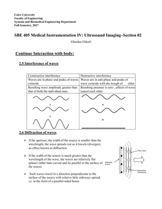
- 1. Cairo University Faculty of Engineering Systems and Biomedical Engineering Department Fall Semester, 2017 SBE 405 Medical Instrumentation IV: Ultrasound Imaging–Section 02 Ghaidaa Eldeeb Continue Interaction with body: 2.5 Interference of waves 2.6 Diffraction of waves If the aperture, the width of the source is smaller than the wavelength, the wave spreads out as it travels (diverges), an effect known as diffraction. If the width of the source is much greater than the wavelength of the wave, the waves are relatively flat (plane) rather than curved and lie parallel to the surface of the source. Such waves travel in a direction perpendicular to the surface of the source with relative little sideways spread, i.e. in the form of a parallel-sided beam. Constructive interference Destructive interference Waves are in phase and peaks of waves are coincide Waves are in anti-phase and peaks of one wave coincide with the trough of other Resulting wave amplitude greater than that of both the individual ones Resulting pressure is zero , effects of waves cancel each other
- 2. Each of the small sources generates a sound wave of the same frequency and amplitude and all are in phase. The curved waves propagate outwards and the parts of the curve which are parallel to the surface of the source align to form plane waves. The other, nonparallel parts of the curved waves tend to interfere destructively and cancel out. 3- Plan Disk: Beam shape Focusing o The surface of the disc source can be considered to be made up of many small elements, each of which emits a spherical wave. o The pressure amplitude at each point in the beam is determined by the sum of the spherical waves from all of the elements. o The different path lengths, from the various elements to the summing point, mean that each of the spherical waves has a different phase when it arrives. Near Field Far Field Non uniform beam Beam diverge Constant diameter Side lobes Length=a^2/⅄ a:radius of source =D/2 ϴ=sin-1(0.61 ⅄/a) Maximum path diff= ⅄/2 Path diff < ⅄/2
- 3. if a ≈ ⅄ near field is short and beam diverge rapidly ( theta ϴ large) a > ⅄ near field is long and little diverge The optimum beam shape is achieved when the aperture is 20 to 30 wavelengths in diameter If freq. inc. near dec , diverge dec. Side lobes are weaker than the main lobe but can give rise to significant echoes if they are incident on a strongly reflecting target adjacent to the main lobe, resulting in acoustic noise in the image Manufacturers normally design their transducers to minimize side lobes. Tis can be done by applying stronger excitation to the centre of the transducer than at the edges, a technique known as apodization. Apodization reduces the amplitude of side lobes but leads to an increase in the width of the main lobe 4- Focusing Solution of near field Beamwidth dec.……resolution is high W=F⅄/a where W: width of beam at focus Focusing is strong when F<a^2/⅄ Focusing methods: o using a curved source o Acoustic lens to a plane source. Lateral resolution is proportional to W and for circular transducer: Lateral Resolution ≈ 2.44 Fλ/D, where D is the aperture diameter Axial resolution = spatial pulse length/2 =TC/2 5- The ultrasound pulse and spectrum To produce a distinct echo which corresponds to a particular interface, ultrasound must be transmitted in the form of a short burst or pulse. To allow echoes from closely spaced interfaces to be resolved separately, the pulse must be short A pulsed wave can be described as being constructed from a range of frequencies centered on the nominal frequency A short pulse gives precise time resolution and hence distance resolution and its echoes contain information at a wide range of frequencies. The information contained in an echo from a long pulse is concentrated near the nominal frequency and gives a stronger signal at that frequency. However, a long pulse results in poor distance resolution.
- 4. 6- Non-linear propagation & harmonic imaging At high pressure amplitudes (>1 MPa), this simple picture breaks down and non-linear propagation effects become noticeable In the high-pressure (compression) parts of the wave, the medium becomes compressed, resulting in an increase in its stiffness and hence an increase in the speed of sound in addition to that the particle motion is in the direction of propagation, resulting in a slight increase c, whereas in the low pressure (rarefaction) parts of the wave motion is in the opposite direction and c is slightly reduced The rapid changes in pressure in the compression part of the wave appear in the pulse spectrum as high frequency components, these are multiples of the original or fundamental frequency f0 known as harmonics. A frequency of 2f0 is known as the second harmonic, 3f0 as the third harmonic and so on. The figure shows that the original pulse spectrum is effectively repeated at these harmonic frequencies. Non-linear propagation results in some of the energy in the pulse being transferred from the fundamental frequency f0 to its harmonics. As the pulse travels further into the medium, the high- frequency components are attenuated more rapidly than the low-frequency components and the pulse shape becomes more rounded again as the overall amplitude is reduced Second harmonic imaging o 1- reduces noise and side lobe artifacts o 2- Improve depth penetration. 7- Acoustic pressure and intensities
- 5. Isptp – the spatial peak temporal peak intensity is the maximum value in the pulse at the point in the beam where it is highest. Isppa – the spatial peak pulse average intensity is the average value over the pulse duration at the point in the beam where it is highest. Ispta – the spatial peak temporal average intensity is temporal average intensity at the point in the beam where it is highest. Isata – the spatial average temporal average intensity is the temporal average intensity averaged over the beam area (usually -6 dB area) 8- Resolution: Refers to the ability to distinguish between objects Spatial Resolution: The ability to distinguish between objects located at different positions in space. o Axial Resolution: The ability to distinguish between echoes originating from two reflectors lying one behind the other along the axis of the ultrasound beam. It is sometimes referred to as Depth Resolution Factors affecting Axial Resolution: - Beam Wavelength (ʎ) - Spatial Pulse length (SPL) - Beam Frequency (f) o Lateral Resolution: The ability to distinguish between two reflectors suited side by side in a direction perpendicular to that of the ultrasound beam. Factors affecting Lateral Resolution: - Beam width - Beam frequency - Scan line density
- 6. Examples: 7-A plane disc transducer, with a diameter of 1.5 cm, is driven at 3 MHz to produce a continuous-wave beam in tissue with a speed of sound of 1500 m s-1. (a) Calculate the near-field length of the beam and its angle of divergence in the far field. (b) Estimate the beam width at the focus if a lens is added with a focal length of 6 cm. 8. Explain how focusing of an ultrasound beam can be achieved and how its effects depend on the dimensions of the transducer and the ultrasound wavelength. 9. Explain the origin of acoustic noise in B-mode images and how it can be reduced by the use of harmonic imaging. 10. The peak value of acoustic pressure measured in an ultrasound beam in water is 1 MPa. What is the corresponding instantaneous intensity in W m-2? Assume the speed of sound in water is 1500 m s-1 and its density is 1000 kg m-3.