Electrostatic field in a coaxial transmission line
Mechanics is a branch of physics which deals with the state of rest
1. Overview of Mechanical Engineering
Lecture 1 CAD/CAM branch first class
2 - 1
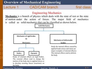
Engineering Mechanics
Mechanics is a branch of physics which deals with the state of rest or the state
of motion under the action of forces. The major field of mechanics
is called as solid mechanics that can be classified as shown below.
Study of external effects on rigid bodies.
The external effects tend to change the
motion of the body due to applied forces or
to develop resisting forces (reactions) on
the body.
Study the internal effects caused by
applied loads (stress and strain are
major examples of internal effects).
The internal effects tend to deform
the body
Engineering Mechanics Asst.Lec Mustafa .A
2. Overview of Mechanical Engineering
The body in which deformation can be neglected in the analysis, is called as
RIGID body (the change in distance between any two of its points is
negligible).
Statics :is the study of bodies that are at rest or move with constant velocity.
Dynamics :is the study of bodies that are in motion.
Statics can consider as a special case of dynamics, in which the acceleration
is zero.
2 - 2
Engineering Mechanics Asst.Lec Mustafa .A
3. Overview of Mechanical Engineering
Fundamental Concepts
It is important to understand the meaning of certain fundamental concepts.
Length: Length is used to locate the position of a point in space and describes the size of a
physical system. (unit: meter m).
Time: Although the principles of statics are time independent, this quantity plays an
important role in the study of dynamics (unit: second s).
Mass: Mass is a measure of a quantity of matter in a body. The mass of a body will not
change unless the body is damaged (unit: kilogram kg).
Particle: Particle has a mass, but its size can be neglected.
Space: The geometric region in which study of body is involved.
Force: Force is the action of one body on another. The action of a force is completely
characterized by its magnitude, direction of its action, and by its point of application. Thus
force is a vector quantity (unit: newton N).
Rigid body: A body is said to be rigid, if the relative positions of any two particles in it do
not change under the action of the forces.
2 - 3
Engineering Mechanics Asst.Lec Mustafa .A
5. Overview of Mechanical Engineering
Newton’s first law: A particle originally at rest or moving in a straight line
with constant velocity, will remain in this state unless the particle is subjected
to an unbalanced force.
Newton’s second law: The acceleration of a particle is proportional to the
force acting on it, and is in the direction of this force
2 - 5
Engineering Mechanics Asst.Lec Mustafa .A
6. Overview of Mechanical Engineering
Newton’s third law: For every action there is an equal and opposite reaction.
The forces of action and reaction are collinear.
Newton’s law of gravitation: The force of attraction (F) between any two
bodies is directly proportional to their masses (m1 and m2) and inversely
proportional to the square of the distance between them (r).
where G is constant of proportionality and is known as constant of gravitation.
2 - 6
Engineering Mechanics Asst.Lec Mustafa .A
7. Overview of Mechanical Engineering
Weight: Weight refers to the gravitational attraction of the earth on a body.
2 - 7
Therefore, a body of mass 1 kg has a weight of 9.81 N.
Engineering Mechanics Asst.Lec Mustafa .A
8. Overview of Mechanical Engineering
Scalars and Vectors
We use two kinds of quantities in mechanics - scalars and vectors.
Scalar Quantities: scalar quantities can be completely described by their
magnitudes (numbers).
Examples of scalars: Mass, length, time, volume, speed, area, and temerature.
Vector Quantities: A vector quantity has both a magnitude and a direction (line of
action). Examples of vectors: Force, acceleration, velocity, and displacement.
Representation of Vectors
A vector quantity can be represented graphically by using a directed line segment
(arrow). The length of the line represents the magnitude (positive numerical
value) of the vector. The direction of the vector is sepecifed by giving an angle
between the arrow and a reference axis (the slope of the line segment). The
headarrow indicates the sense of direction of the vector.
2 - 8
Engineering Mechanics Asst.Lec Mustafa .A
11. Trigonometry Functions Of A Right-Angle Triangle
sine = opposite side = o = cosine
hypotenuse h
cosine = adjacent side = a = sine
hypotenuse h
tangent = opposite side = o
adjacent side a
tangent = sin
cos
h
o
a
Engineering Mechanics Asst.Lec Mustafa .A
12. Sine And Cosine Rules
For triangles that are not right-angle, the following two laws
are important in vector algebra introduced in chapter two
later:
Sine Rule a = b = c
sin sin sin
Cosine Rule a2 = b2 + c2 – 2bc cos
b2 = a2 + c2 – 2ac cos
c2 = a2 + b2 – 2ab cos
Engineering Mechanics Asst.Lec Mustafa .A
13. If the cosine rule is applied to a right-angle
triangle where = 90 0 , and applying to
equation bellow.
i.e. a2 = b2 + c2 – 2bc cos 90 0
since cos 90 0 = 0
a2 = b2 + c2
(Pythagoras Theorem)
c a
90 0
b
Engineering Mechanics Asst.Lec Mustafa .A
14. Example
Find the length of the unknown side a and the angle .
200
6m 4m
a
Cosine rule : a2 = b2+c2-2bccos
i.e. a2 = 62+42-2x6x4cos200
a = 2.63m
Sine rule : 2.63 = 6
sin 200 sin
= 6.9
= 36 +16-6x4xcos200
= 51.30
sine = 6 x sin 200
2.63
Engineering Mechanics Asst.Lec Mustafa .A
15. we know this to be in the second quadrant,
Hence = 180 – 51.4 = 128.6 0
Check : 62 = 2.632 - 42 - 2x2.63x4 cos
cos = 2.632 + 42 – 62
2x2.63x4
= - 0.634
= 128.6 0
Engineering Mechanics Asst.Lec Mustafa .A
16. Geometry
Some of the basic rules are shown below:
Sum of supplementary angles = 180 0
+ = 180 0
A straight line intersecting
two parallel lines
= , =
= , =
Engineering Mechanics Asst.Lec Mustafa .A
17. Similar triangles ABC and ADE, by proportion
B
C
AB = BC = AC
AD DE AE
Hence if AB = 6, AD = 3 and BC = 4,
Then,
6 = 4
3 DE
DE = (3 x 4)
3
= 2
D
A
E
Engineering Mechanics Asst.Lec Mustafa .A
18. Overview of Mechanical Engineering
Rectangular Components of a Force: Unit Vectors
2 - 18
• Vector components may be expressed as products of
the vectors with the scalar magnitudes of the vector
components.
Fx and Fy are referred to as the scalar components of F
• May resolve a force vector into perpendicular
components so that the resulting parallelogram is a
rectangle. Fx and Fy are referred to as rectangular
vector components and
F= Fx + Fy
• Define perpendicular vectors i and j which are
parallel to the x and y axes.
F= Fx i + Fy j
Engineering Mechanics Asst.Lec Mustafa .A
21. Overview of Mechanical Engineering
2 - 21
Quantity Dimensional symbol unit Unit symbol
Mass M Kilogram kg
Length L Meter m
Time T Second s
Force F Newton
F=ma
2
N(=kg.m/s)
Process Exponentialform Prefix SIsymbol
*
Multiple
1000000000
1000000
1000
9
10
6
10
3
10
giga
mega
kilo
G
M
k
Submultiple
/
0.001
0.000001
0.000000001
-3
10
-6
10
-9
10
milli
micro
nano
m
µ
n
Engineering Mechanics Asst.Lec Mustafa .A
23. Overview of Mechanical Engineering
2 - 23
F1
θ
F2
Engineering Mechanics Asst.Lec Mustafa .A
24. Overview of Mechanical Engineering
2 - 24
θ1
θ2
F1
v
u
F2
θ3
Engineering Mechanics Asst.Lec Mustafa .A
25. Overview of Mechanical Engineering
Example 2: Combine the two forces P and T into a single equivalent force R.
(Forces given in Newton and dimensions in cm).
2 - 25
Solution:
Graphical solution: The parallelogram for the vector
addition of the two forces is constructed to scale as
shown in Fig. a. The angle α must be determine to
construct of the parallelogram.
Engineering Mechanics Asst.Lec Mustafa .A
26. Overview of Mechanical Engineering
2 - 26
N
N
N
N
N
Engineering Mechanics Asst.Lec Mustafa .A
27. Overview of Mechanical Engineering
Example 3:
The two forces Q and P act on a bolt at point A as shown in the figure.
Determine their resultant
2 - 27
Engineering Mechanics Asst.Lec Mustafa .A
29. Overview of Mechanical Engineering
Example 4:
The forces F1, F2, and F3 act on point A of the bracket. Determine the x and y
scalar components of each of the three forces.
2 - 29