Preparing for EASA Mod.15 Gas turbine engines . Then avoid reading lengthy books here are my personal short notes and explanations and important topics for Mod.15 .
THIS SLIDE PROVIDE THE INFORMATION ABOUT
" AFTERBURNEFR" which is used in jet
this slide is useful for the engineering student ;
and i hope that you enjoy this slide
Aircraft Air Conditioning And Pressurisation SystemCahit Kutay Uysal
At this presentation, I try to explain aircraft pressurization systems and air conditioning systems. I hope it will be useful source to understand aircraft systems easily.
THIS PRESENTATION TAKES OVERVIEW OF AIRCRAFT CABIN PRESSURIZATION. IN THIS I EXPLAINED BASIC SYSTEM USED FOR PRESSURIZATION, AND HOW THIS SYSTEM IS SAFE, PRECISE. AND HOW AIR IS KEPT HEALTHY.
For Video Lecture of this presentation: https://youtu.be/NAjezfbWh4Y
The topics covered in this session are, drag, categories of drag, drag polar equation and drag polar graph, drag polar derivation, induced drag coefficient.
Attention! "Gate Aerospace Engineering aspirants", A virtual guide for gate aerospace engineering is provided in "Age of Aerospace" blog for helping you meticulously prepare for gate examination. Respective notes of individual subjects are provided as 'Embedded Google Docs' which are frequently updated. This comprehensive guide is intended to efficiently serve as an extensive collection of online resources for "GATE Aerospace Engineering" which can be accessed free of cost. Use the following link to access the study material
https://ageofaerospace.blogspot.com/p/gate-aerospace.html
SAIF ALDIN ALI MADIN
سيف الدين علي ماضي
S96aif@gmail.com
Presentation
on
Axial Flow Compressor
Introduction
Construction
Working
Design
Main Parts
Stalling
Surging
Stage Losses
Advantages - Disadvantages & Applications
ABSTRACT
Air compressor operation and care. Compressed air is one of the most used service fluids in industry. The article introduces the basic design concepts of an air compressor and discusses some of the common problems and solutions found in both reciprocating (piston goes up and down) and rotary screw (twin, meshed, rotating, helix) air compressors.
International Journal of Engineering and Science Invention (IJESI) is an international journal intended for professionals and researchers in all fields of computer science and electronics. IJESI publishes research articles and reviews within the whole field Engineering Science and Technology, new teaching methods, assessment, validation and the impact of new technologies and it will continue to provide information on the latest trends and developments in this ever-expanding subject. The publications of papers are selected through double peer reviewed to ensure originality, relevance, and readability. The articles published in our journal can be accessed online.
What Does the PARKTRONIC Inoperative, See Owner's Manual Message Mean for You...Autohaus Service and Sales
Learn what "PARKTRONIC Inoperative, See Owner's Manual" means for your Mercedes-Benz. This message indicates a malfunction in the parking assistance system, potentially due to sensor issues or electrical faults. Prompt attention is crucial to ensure safety and functionality. Follow steps outlined for diagnosis and repair in the owner's manual.
Symptoms like intermittent starting and key recognition errors signal potential problems with your Mercedes’ EIS. Use diagnostic steps like error code checks and spare key tests. Professional diagnosis and solutions like EIS replacement ensure safe driving. Consult a qualified technician for accurate diagnosis and repair.
Core technology of Hyundai Motor Group's EV platform 'E-GMP'Hyundai Motor Group
What’s the force behind Hyundai Motor Group's EV performance and quality?
Maximized driving performance and quick charging time through high-density battery pack and fast charging technology and applicable to various vehicle types!
Discover more about Hyundai Motor Group’s EV platform ‘E-GMP’!
In this presentation, we have discussed a very important feature of BMW X5 cars… the Comfort Access. Things that can significantly limit its functionality. And things that you can try to restore the functionality of such a convenient feature of your vehicle.
𝘼𝙣𝙩𝙞𝙦𝙪𝙚 𝙋𝙡𝙖𝙨𝙩𝙞𝙘 𝙏𝙧𝙖𝙙𝙚𝙧𝙨 𝙞𝙨 𝙫𝙚𝙧𝙮 𝙛𝙖𝙢𝙤𝙪𝙨 𝙛𝙤𝙧 𝙢𝙖𝙣𝙪𝙛𝙖𝙘𝙩𝙪𝙧𝙞𝙣𝙜 𝙩𝙝𝙚𝙞𝙧 𝙥𝙧𝙤𝙙𝙪𝙘𝙩𝙨. 𝙒𝙚 𝙝𝙖𝙫𝙚 𝙖𝙡𝙡 𝙩𝙝𝙚 𝙥𝙡𝙖𝙨𝙩𝙞𝙘 𝙜𝙧𝙖𝙣𝙪𝙡𝙚𝙨 𝙪𝙨𝙚𝙙 𝙞𝙣 𝙖𝙪𝙩𝙤𝙢𝙤𝙩𝙞𝙫𝙚 𝙖𝙣𝙙 𝙖𝙪𝙩𝙤 𝙥𝙖𝙧𝙩𝙨 𝙖𝙣𝙙 𝙖𝙡𝙡 𝙩𝙝𝙚 𝙛𝙖𝙢𝙤𝙪𝙨 𝙘𝙤𝙢𝙥𝙖𝙣𝙞𝙚𝙨 𝙗𝙪𝙮 𝙩𝙝𝙚 𝙜𝙧𝙖𝙣𝙪𝙡𝙚𝙨 𝙛𝙧𝙤𝙢 𝙪𝙨.
Over the 10 years, we have gained a strong foothold in the market due to our range's high quality, competitive prices, and time-lined delivery schedules.
The Future of Autonomous Vehicles | civilthings.com | Detailed informationgettygaming1
civilthings.com Present Autonomous vehicles, also known as self-driving cars, represent a groundbreaking advancement in transportation technology. These vehicles utilize sophisticated sensors, advanced software, and machine learning algorithms to navigate roads and transport passengers without human intervention. Major companies in the autonomous vehicle industry are investing heavily in the development and testing of these innovative machines, aiming to enhance safety, efficiency, and convenience on the roads.
The autonomous vehicle market is rapidly expanding, driven by technological progress and increasing consumer interest. With the advent of autonomous vehicle technology, the future of transportation promises significant changes, including reduced traffic accidents and lower emissions. However, the widespread adoption of autonomous vehicles faces challenges, such as regulatory hurdles, safety concerns, and public acceptance.
Autonomous vehicle regulations and legislation are evolving to address these issues, ensuring that the integration of self-driving cars into everyday life is smooth and secure. As the industry grows, news and trends related to autonomous vehicles continue to capture global attention. From the development of cutting-edge sensors to advancements in autonomous vehicle software, this sector is poised to revolutionize how we think about mobility.
Stay informed about the latest in autonomous vehicle technology, industry developments, and market trends to understand the profound impact these vehicles will have on our future.
The Future of Autonomous Vehicles | civilthings.com | Detailed information
GAS TURBINE ENGINES CONSTRUCTION PART 1 - INLET
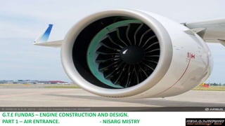
1. G.T.E FUNDAS – ENGINE CONSTRUCTION AND DESIGN.
PART 1 – AIR ENTRANCE. - NISARG MISTRY
2. THE INLET DUCT
The Inlet of a turbine engine is typically located at the front of the G.T.E which is formed by
structural parts located forward of the compressor.
It is normally considered as a part of the Airframe and not the PWR plant.
Its purpose is to admit air to the forward end of the compressor .
The length , shape and placement of the duct is determined to a great extent by the location of the
engine in the aircraft.
Not only must the duct be large enough to supply the proper airflow , but it must be shaped correctly
to deliver the air to the front of the compressor with an even pressure distribution.
Poor air pressure and velocity distribution at the front of the compressor may result in compressor
stall and/or compressor blade vibration.
*Another primary task a duct must do during flight operation is to convert kinetic energy of the
rapid moving inlet airstream into a Ram pressure rise inside the duct. To do this it must be
shaped so that the ram velocity is slowly and smoothly decreasing , while the Ram pressure is
slowly and smoothly rising.
3. *The Air inlet is designed to recover as much total pressure of the free stream air as possible and
deliver it to the compressor . This is k/a “RAM RECOVERY” or “PRESSURE RECOVERY”.
In addition to recovering & maintaining the pressure of the free stream air , inlets can be shaped to
increase air pressure above atmospheric pressure , this Ram effect causes air to “PILE UP” (jama
hona) in the inlet. The faster the Aircraft flies the more air piles up and the higher the inlet air
pressure .
The inlet are rated in two ways -
1) - RAM RECOVERY POINT - The Ram Recovery point is that Aircraft speed at which the Ram-
pressure rise is equal to the “Friction pressure Losses” (due to skin friction drag) or that airspeed
at which the compressor inlet total pressure is equal to the outside ambient air pressure.
A good subsonic duct will have a low RAM Recovery point (about 160Mph or 257.4 Km/Hr).
2) – DUCT PRESSURE EFFECIENCY RATIO - It is defined as the ability of the duct to convert
the kinetic energy or dynamic pressure energy at the inlet of the duct at (Pt1 ) into static pressure
energy at the inlet of the compressor (Pt2 ) without a loss in total pressure. It will have a high value
of 98% if the friction loss is low and if the pressure rise is accomplished with small loses.
5. 1) – SUBSONIC INLET -
The air inlet duct also provides a uniform supply of air to the compressor for efficient operation.
The inlet duct is designed to cause as little drag as possible . It takes only a small obstruction to
the airflow inside a duct to cause a severe loss of efficiency
It should deliver maximum volume of air with a minimum turbulence.
This inlet is for subsonic range aircrafts which flies below Mach 1.
On a typical subsonic inlet, the surface of the inlet from outside to inside is a continuous smooth
curve with some thickness from inside to outside. The most upstream portion of the inlet is called
the highlight, or the inlet lip. A subsonic aircraft has an inlet with a relatively thick lip.
Inlet lip
6. To prevent the duct from damage or corrosion an “Inlet Cover” should be
installed anytime the engine isn't operating.
Inlet cover.
Some aircrafts such as military aircraft &
other old commercial aircraft had a wing
mounted inlet or a fuselage mounted inlet.
Wing inlet.
Fuselage Mounted inlet.
7. The design of an inlet duct can also vary by the type of engine used.
Also the amount of air passing through the engine is dependent upon three factors :
1) – The compressor speed.
2) – The forward speed of the Aircraft .
3) – The density of ambient Air.
*Inlet ducts can also be used to pre-clean the air before it enters the compressor .
Traditional filters or screens are not used becoz they would offer too much resistance
to air flow. Particle separators for turboshaft/turboprop engines take advantage of
the natural inertial property of matter to continue in straight line.
DGCA question
Traditional Inlet screen
8. -Ref. Aircraft Gas Turbine engine tech. by Irwin E.Treager page -164 3rd edition.
9. 2) – SUPERSONIC INLET -
The design and construction of the inlet duct for high speed aircraft is of critical importance becoz of
its profound effect on both the airframe and engine.
The supersonic inlet is complex in construction becoz not only must the air be delivered to the face of
the compressor but at an acceptable mass , flow rate, velocity , angle and pressure distribution , it
must it must do this under wide extremes of aircraft speed , altitude and attitude and with as little
loss of total pressure as possible.
At supersonic speed the Bernoulli's theorem is reversed.
In this type of duct , the air is slowed down to MACH 1.0 in the convergent portion of the duct and a
shock-wave is formed. When the air flows through the shock wave , it shows to a subsonic speed & is
further slowed in the divergent portion of the duct before it enters the compressor.
In this way the supersonic inlet works. But when this aircraft flies at subsonic range then this fixed
type supersonic inlet won’t work.
Hence, aircraft that flies at supersonic ranges normally have variable inlet ducts that change their
shape as the airspeed increases.
10. So, the variation in the area of this type of duct is done either by lowering or raising a wedge (just
as a flap which is in RAM AIR INLET) or by moving a tapered plug in or out of the duct.
Therefore, when the aircraft is at subsonic speeds the wedge is raised creating a divergence at
the front part of inlet so the pressure increases and velocity decreases , while going towards
throat again the velocity increases a little to continue the flow and there is divergence at the front
of the compressor creating an increase in total pressure at Pt2 .
Compressor.Wedge.
At Subsonic
At supersonic
Throat Wedge
11. 3) – BELL MOUTH INLET -
This type of inlet is essentially a bell-shaped (GHANTA ) ) funnel having
carefully rounded shoulders , which offer practically no air resistance . The
duct loss is so small that it is considered zero , and all engine performance
data can be gathered without any correction of inlet duct loss being
necessary.
Its interesting to note that the engine manufacturers rate their engines
using this type of inlet.
Next Topic compressor stay tuned….