SlideShare a Scribd company logo
1 of 10
Download to read offline
Monday, April 13, 2015    1 | P a g e  
 
PRODUCT DEVELOPMENT LABORATORY II 
PRODUCT: HOME APPLIANCES CONTROL USING RF COMMUNICATION 
OBJECTIVE: To design an analog circuit that can control home appliances using a remote 
based on Radio Frequency Communication. 
FEATURES:  
 Circuit has been designed without using a microcontroller development board and hence 
cost efficient. 
 The appliances can be controlled from 100 meters range. Further range can be extended to 
a larger distance by increasing the height of antenna. 
 User friendly (to understand the control/working and its applications). 
 
COMPONENTS USED 
Sl No.  Component  Specification 
(Tx‐Transmitter Rx‐Receiver) 
Quantity  Approx. Price
(in Rs.) 
01  Encoder  HT12E (Tx)  01  60 
02  Decoder  HT12D (Rx)  01  60 
03  RF module (ASK)  RF Transmitter (Tx) (434 MHz)  01  110 
04  RF module (ASK)  RF Receiver (Rx) (434 MHz)  01  110 
05  Relays   12V Relay SPDT (Rx)   04  80 
06  Relay Driver  ULN2003 (Rx)  01  20 
07  Switches  Push Button Switches (Tx)  05  25 
08  Resistors  1M, 330R, 33K, 220R (Tx + Rx)  01 
(220R‐4) 
15 
09  Diode  LED (Green and Red) (Tx + Rx)  Green‐4 
Red‐2 
20 
10  IC Base  IC Base (Tx + Rx)  05  30 
11   Connectors  Female Connectors (4 pins)  03  09 
12  Connecting wires  Jumper wires (F/M‐F) (Tx + Rx)  Bunch  5 per piece 
13  Antenna  Can be made using connecting 
wires (Tx + Rx) 
   
14  Load  Bulbs, Fan ( Motor) etc. (Rx)  04   
15  PCB   Vero Board (PCB 4*4, 2*3)  02  80(Total 700) 


Monday, April 13, 2015    2 | P a g e  
 
BLOCK DIAGRAM 


Output of the decoder is connected to the relay driver which is then fed to relays that 
control the loads. 


Monday, April 13, 2015    3 | P a g e  
 
COMPONENTS DESCRIPTION 
HT12E 
The 212
 encoders are a series of CMOS LSIs for remote control system 
applications. They are capable of encoding information which consists of 
N address bits and 12‐N data bits. Each address/data input can be set to 
one  of  the  two  logic  states.  The  programmed  addresses/data  are 
transmitted  together  with  the  header  bits  via  an  RF  or  an  infrared 
transmission medium upon receipt of a trigger signal. The capability to 
select  a  TE  trigger  on  the  HT12E  further  enhances  the  application 
flexibility of the 212
 series of encoders.  
Features 
‐ Operating voltage ‐ 2.4V‐12V for the HT12E. 
‐ Low power and high noise immunity CMOS technology. 
‐ Low standby current: 0.1 uA (typ.) at VDD = 5V. 
‐ Four words transmission for the HT12E. 
‐ Built‐in oscillator needs only 5% resistor. 
‐ Data code has positive polarity. 
‐ Minimal external components. 
‐ Pair with Holtek’s 212
 series of decoders. 
‐ 18‐pin DIP, 20‐pin SOP package. 
HT12D 
The 212
 decoders are a series of CMOS LSIs for remote control system 
applications. They are paired with Holtek’s 212
 series of encoders (refer to 
the encoder/decoder cross reference table). For proper operation, a pair 
of encoder/decoder with the same number of addresses and data format 
should be chosen. The decoders receive serial addresses and data from a 
programmed 212
 series of encoders that are transmitted by a carrier using 
an RF or an IR transmission medium. They compare the serial input data 
three  times  continuously  with  their  local  addresses.  If  no  error  or 
unmatched codes are found, the input data codes are decoded and then 
transferred to the output pins. The VT pin also goes high to indicate a valid 
transmission.  The  212
  series  of  decoders  are  capable  of  decoding 
informations that consist of N bits of address and 12‐N bits of data. Of this 
series, the HT12D is arranged to provide 8 address bits and 4 data bits. 
Features 
‐ Operating voltage: 2.4V~12V. 
‐ Low power and high noise immunity CMOS technology. 
‐ Low standby current. 
‐ Capable of decoding 12 bits of information. 
‐ Binary address setting. 
 
Monday, April 13, 2015    4 | P a g e  
 
‐ Received codes are checked 3 times. 
‐ Address/Data number combination. 
‐ HT12D: 8 address bits and 4 data bits. 
‐ Built‐in oscillator needs only 5% resistor. 
‐ Valid transmission indicator. 
‐ Easy interface with an RF or an infrared transmission medium. 
‐ Minimal external components. 
‐ Pair with Holtek’s 212
 series of encoders. 
‐ 18‐pin DIP, 20‐pin SOP package. 
RF ASK Module (434 MHz)  
The RF module, as the name suggests, operates at Radio Frequency. The 
corresponding frequency range varies between 30 kHz & 300 GHz. In this 
RF system, the digital data is represented as variations in the amplitude 
of  carrier  wave.  This  kind  of  modulation  is  known  as  Amplitude  Shift 
Keying (ASK). 
Why RF is preferred over IR? 
Transmission  through  RF  is  better  than  IR  (infrared)  because  of  many 
reasons.  
‐ Firstly, signals through RF can travel through larger distances making 
it suitable for long range applications.  
‐ Also, while IR mostly operates in line‐of‐sight mode, RF signals can 
travel  even  when  there  is  an  obstruction  between  transmitter  & 
receiver. 
‐  Next,  RF  transmission  is  more  strong  and  reliable  than  IR 
transmission.  
‐ RF communication uses a specific frequency unlike IR signals which 
are affected by other IR emitting sources. 
This RF module comprises of an RF Transmitter and an RF Receiver. The 
transmitter/receiver (Tx/Rx) pair operates at a frequency of 434 MHz. An 
RF transmitter receives serial data and transmits it wirelessly through RF 
through its antenna connected at pin4. The transmission occurs at the 
rate of 1Kbps ‐ 10Kbps.The transmitted data is received by an RF receiver 
operating at the same frequency as that of the transmitter. 
The RF module is often used along with a pair of encoder/decoder. The 
encoder is used for encoding parallel data for transmission feed while 
reception is decoded by a decoder. HT12E‐HT12D, HT640‐HT648, etc. are 
some commonly used encoder/decoder pair ICs. 


Monday, April 13, 2015    5 | P a g e  
 
RELAY 
A  relay  is  an  electrically  operated  switch.  Many  relays  use 
an electromagnet to mechanically operate a switch, but other operating 
principles are also used, such as solid‐state relays. Relays are used where 
it is necessary to control a circuit by a low‐power signal (with complete 
electrical  isolation  between  control  and  controlled  circuits),  or  where 
several circuits must be controlled by one signal. A relay switches one or 
more poles, each of whose contacts can be thrown by energizing the coil. 
Normally‐open  (NO)  contacts  connect  the  circuit  when  the  relay  is 
activated; the circuit is disconnected when the relay is inactive. It is also 
called a "Form A" contact or "make" contact. NO contacts may also be 
distinguished as "early‐make" or "NOEM", which means that the contacts 
close before the button or switch is fully engaged. Normally‐closed (NC) 
contacts disconnect the circuit when the relay is activated; the circuit is 
connected when the relay is inactive. It is also called a "Form B" contact 
or "break" contact. NC contacts may also be distinguished as "late‐break" 
or "NCLB", which means that the contacts stay closed until the button or 
switch is fully disengaged. SPDT ‐ Single Pole Double Throw, a common 
terminal connects to either of two others. Including two for the coil, such 
a relay has five terminals in total.  
RELAY DRIVER ULN2003A 
The  ULN2003A  is  a  high‐voltage,  high‐current  Darlington  transistor  array.  It 
consists of seven NPN Darlington pairs that feature high‐voltage outputs with 
common‐cathode fly back diodes for switching inductive loads. The drivers can 
be  paralleled for  higher  current capability, even stacking one  chip on  top of 
another, both electrically and physically has been done. Generally it can also be 
used for interfacing with stepper motor, where the motor requires high ratings 
which cannot be provided by other interfacing devices. 
Features 
 500 mA rated collector current (single output) 
 50 V output 
 Includes output fly back diodes 
 Inputs compatible with various types of logic 
Typical  usage  of  the  ULN2003A  is  to  drive  relays,  lamp  and  LED 
displays or stepper motors Logic buffers, Line drivers, Hammer driver. 


Monday, April 13, 2015    6 | P a g e  
 
CIRCUIT DIAGRAM 


TRANSMITTER             RECEIVER 


Monday, April 13, 2015    7 | P a g e  
 
WORKING 
This circuit utilizes the RF module (Tx/Rx) for making a wireless remote, which could be used 
to drive an output from a distant place. RF module, as the name suggests, uses radio frequency 
to send signals. These signals are transmitted at a particular frequency and a baud rate. A 
receiver can receive these signals only if it is configured for that frequency. A four channel 
encoder/decoder pair has also been used in this system. The input signals, at the transmitter 
side, are taken through four switches while the outputs are monitored on a set of four LEDs 
corresponding to each input switch. The circuit can be used for designing Remote Appliance 
Control system. The outputs from the receiver can drive corresponding relays connected to 
any household appliance. 
This radio frequency (RF) transmission system employs Amplitude Shift Keying (ASK) with 
transmitter/receiver (Tx/Rx) pair operating at 434 MHz. The transmitter module takes serial 
input and transmits these signals through RF. The transmitted signals are received by the 
receiver module placed away from the source of transmission. The system allows one way 
communication between two nodes, namely, transmission and reception. The RF module has 
been used in conjunction with a set of four channel encoder/decoder ICs. Here HT12E & 
HT12D  have  been  used  as  encoder  and  decoder  respectively.  The  encoder  converts  the 
parallel inputs (from the remote switches) into serial set of signals. These signals are serially 
transferred through RF to the reception point. The decoder is used after the RF receiver to 
decode the serial format and retrieve the original signals as outputs. These outputs can be 
observed on corresponding LEDs. 
Encoder IC (HT12E) receives parallel data in the form of address bits and control bits. The 
control signals from remote switches along with 8 address bits constitute a set of 12 parallel 
signals.  The  encoder  HT12E  encodes  these  parallel  signals  into  serial  bits.  Transmission  is 
enabled by providing ground to pin14 which is active low. The control signals are given at pins 
10‐13 of HT12E. The serial data is fed to the RF transmitter through pin17 of HT12E. 
Transmitter, upon receiving serial data from encoder IC (HT12E), transmits it wirelessly to the 
RF receiver. The receiver, upon receiving these signals, sends them to the decoder IC (HT12D) 
through pin2. The serial data is received at the data pin (DIN, pin14) of HT12D. The decoder 
then retrieves the original parallel format from the received serial data. 
When no signal is received at data pin of HT12D, it remains in standby mode and consumes 
very less current (less than 1μA) for a voltage of 5V. When signal is received by receiver, it is 
given to DIN pin (pin14) of HT12D. On reception of signal, oscillator of HT12D gets activated. 
IC HT12D then decodes the serial data and checks the address bits three times. If these bits 
match with the local address pins (pins 1‐8) of HT12D, then it puts the data bits on its data 
pins (pins 10‐13) and makes the VT pin high. An LED is connected to VT pin (pin17) of the 
decoder. This LED works as an indicator to indicate a valid transmission. The corresponding 
output is thus generated at the data pins of decoder IC. A signal is sent by lowering any or all  
Monday, April 13, 2015    8 | P a g e  
 
the pins 10‐13 of HT12E and corresponding signal is received at receiver’s end (at HT12D). 
Address bits are configured by using the by using the first 8 pins of both encoder and decoder 
ICs. To send a particular signal, address bits must be same at encoder and decoder ICs. By 
configuring the address bits properly, a single RF transmitter can also be used to control 
different RF receivers of same frequency.  
To summarize, on each transmission, 12 bits of data is transmitted consisting of 8 address bits 
and 4 data bits. The signal is received at receiver’s end which is then fed into decoder IC. If 
address bits get matched, decoder converts it into parallel data and the corresponding data 
bits get lowered which could be then used to drive the LEDs.  
Amplitude Shift Keying (ASK) 
It  is  a  form  of  amplitude  modulation  that  represents  digital  data  as  variations  in 
the amplitude of a carrier wave. In an ASK system, the binary symbol 1 is represented by 
transmitting a fixed‐amplitude carrier wave and fixed frequency for a bit duration of T seconds. 
If the signal value is 1 then the carrier signal will be transmitted; otherwise, a signal value of 0 
will be transmitted. 
Antenna Specification 
‐ The recommended length of the antenna is 17cm. 
‐ Coiling the antenna up will shorten the range.  
‐ For best reception mount it vertical and on a suitable ground plane, (a conducting surface) 
as high as one can manage.  
 
IMPLEMENTATION AND TESTING 
The circuit is simulated using NI Multisim and the transmitter and receiver circuits were 
tested  on  breadboard.  The  final  circuit  was  implemented  on  Vero‐board  by  manual 
Soldering. After soldering the components on to the PCB, the boards were thoroughly cleaned 
for removing any residual flux and wire leads. All the components are checked for their values 
and proper orientation if applicable. Before ICs were inserted into the sockets, power was 
applied to the board and voltages were measured at the IC power points. Other DC voltages 
were also checked if possible. Then power was removed from the board, and ICs were inserted 
into  the  sockets,  checking  the  proper  orientation.  Power  was  again  applied  to  the  board 
expected  voltages  and  signals  were  monitored.  The  supply  voltages  were  monitored  and 
verified. Working was tested and the product was completed. 


Monday, April 13, 2015    9 | P a g e  
 
APPLICATIONS 
 Radio remote control is used to control distance objects using a variety of radio signals 
transmitted by the remote control device. As a complementary method to infrared remote 
controls,  the  radio  remote  control  is  used  with  electric  garage  door  or  gate  openers, 
automatic barrier systems, burglar alarms and industrial automation systems. 
 Home appliances control and industrial applications 
 RF is used in jamming circuit for military purposes. 
 A remote controlled device primarily saves a lot of time and energy. Its significance in 
today’s world is immense when people don’t have to unnecessarily waste their time in 
operating the appliances by being near to the appliance. They can operate it while they’re 
engrossed in whatever task they’re doing and don’t have to bother leaving it in between.  
 The remote control can extend up to a long distance depending on the frequency used 
and the efficiency of the circuit. It is an advantage that it can be operated from distances.  
 Tediousness of operating the appliance in its close proximity is done away with. The circuit 
has the advantages that it can be easily implemented using easily available and low cost 
components. The maintenance is also easy.  
Advantages 
‐ Highly Sensitive 
‐ Very low noise 
‐ Low cost and reliable circuit 
‐ The appliances can be controlled from 100 meters range. Further range can be extended 
to a larger distance by increasing the height of antenna. 
‐ Can handle heavy loads up to 7 Amperes.  
 
CONCLUSION 
The product to demonstrate the remote controlled operation of multiple home appliances is 
designed. 


Monday, April 13, 2015    10 | P a g e  
 
  
REFERENCES  
  
1. http://arif‐ece.blogspot.com/2010/05/tv‐remote‐controlled‐home‐appliance.html  
2. http://arif‐ece.blogspot.com/2010_05_01_archive.html  
3. http://www.circuitstoday.com/category/remote‐circuits  
4. http://www.satsleuth.com/schematics.htm  
5. http://www.printsasia.com/book/Electronic‐Projects‐for‐Beginners‐Using‐Easily‐
AvailableElectronic‐Components‐with‐A‐Primer‐on‐Basic‐8122301525‐9788122301526  
6. http://www.dapj.net/hobby/?paged=2  
7. http://extremeelectronics.co.in/  


More Related Content

What's hot

Gsm library for proteus the engineering projects
Gsm library for proteus   the engineering projectsGsm library for proteus   the engineering projects
Gsm library for proteus the engineering projects
ZerihunDemere
 
Interfacing rs232
Interfacing rs232Interfacing rs232
Interfacing rs232
PRADEEP
 
digital audio broadcasting
digital audio broadcastingdigital audio broadcasting
digital audio broadcasting
Ram B
 
VOICE OPERATED WHEELCHAIR
VOICE OPERATED WHEELCHAIRVOICE OPERATED WHEELCHAIR
VOICE OPERATED WHEELCHAIR
Mandar Jadhav
 

What's hot (20)

Introduction to Node MCU
Introduction to Node MCUIntroduction to Node MCU
Introduction to Node MCU
 
Gsm library for proteus the engineering projects
Gsm library for proteus   the engineering projectsGsm library for proteus   the engineering projects
Gsm library for proteus the engineering projects
 
microcontroller basics
microcontroller basicsmicrocontroller basics
microcontroller basics
 
Interfacing rs232
Interfacing rs232Interfacing rs232
Interfacing rs232
 
Nodemcu - introduction
Nodemcu - introductionNodemcu - introduction
Nodemcu - introduction
 
Project report
Project reportProject report
Project report
 
digital audio broadcasting
digital audio broadcastingdigital audio broadcasting
digital audio broadcasting
 
Bluetooth Controlled Robot/Car
Bluetooth Controlled Robot/CarBluetooth Controlled Robot/Car
Bluetooth Controlled Robot/Car
 
Microprocessor and Microcontroller lec1
Microprocessor and Microcontroller lec1Microprocessor and Microcontroller lec1
Microprocessor and Microcontroller lec1
 
Arduino and its hw architecture
Arduino and its hw architectureArduino and its hw architecture
Arduino and its hw architecture
 
memory 8051
memory  8051memory  8051
memory 8051
 
Bluetooth controlled robot
Bluetooth controlled robotBluetooth controlled robot
Bluetooth controlled robot
 
Bluetooth based Home Automation
Bluetooth based Home AutomationBluetooth based Home Automation
Bluetooth based Home Automation
 
Smart Home Automation And security System
Smart Home Automation And security SystemSmart Home Automation And security System
Smart Home Automation And security System
 
IR Remote Control
IR Remote ControlIR Remote Control
IR Remote Control
 
Obstacle Avoidance ROBOT using ARDUINO
Obstacle Avoidance ROBOT using ARDUINOObstacle Avoidance ROBOT using ARDUINO
Obstacle Avoidance ROBOT using ARDUINO
 
VOICE OPERATED WHEELCHAIR
VOICE OPERATED WHEELCHAIRVOICE OPERATED WHEELCHAIR
VOICE OPERATED WHEELCHAIR
 
Obstacle Avoidance Robot
Obstacle Avoidance RobotObstacle Avoidance Robot
Obstacle Avoidance Robot
 
Arduino bluetooth controlled robot
Arduino bluetooth controlled robotArduino bluetooth controlled robot
Arduino bluetooth controlled robot
 
Robo wireless controll
Robo wireless controllRobo wireless controll
Robo wireless controll
 

Viewers also liked

Ppt rf based home automation system 1
Ppt rf based home automation system 1Ppt rf based home automation system 1
Ppt rf based home automation system 1
Ankit Gosain
 
Remote control for home appliances
Remote control for home appliancesRemote control for home appliances
Remote control for home appliances
Bharath University
 
102642452 infrared-remote-switch-project-report
102642452 infrared-remote-switch-project-report102642452 infrared-remote-switch-project-report
102642452 infrared-remote-switch-project-report
isnadh
 
Infrared Remote Controlled Devices
Infrared Remote Controlled DevicesInfrared Remote Controlled Devices
Infrared Remote Controlled Devices
Narayan Jaiswal
 
Microcontroller 8051
Microcontroller 8051Microcontroller 8051
Microcontroller 8051
Rashmi
 
Home automation ppt-kamal lamichhane
Home automation ppt-kamal lamichhaneHome automation ppt-kamal lamichhane
Home automation ppt-kamal lamichhane
Kamal Lamichhane
 
RF transmitter & receiver
RF transmitter & receiverRF transmitter & receiver
RF transmitter & receiver
codexdesign
 

Viewers also liked (20)

RF Based Home Automation System
RF Based Home Automation SystemRF Based Home Automation System
RF Based Home Automation System
 
Ppt rf based home automation system 1
Ppt rf based home automation system 1Ppt rf based home automation system 1
Ppt rf based home automation system 1
 
Report on remote control home appliances.
Report on remote control home appliances.Report on remote control home appliances.
Report on remote control home appliances.
 
HOME AUTOMATION SYSTEM USING RADIO FREQUENCY
HOME AUTOMATION SYSTEM USING RADIO FREQUENCYHOME AUTOMATION SYSTEM USING RADIO FREQUENCY
HOME AUTOMATION SYSTEM USING RADIO FREQUENCY
 
Rf based home automation
Rf based home automationRf based home automation
Rf based home automation
 
Remote controlling of home appliance by moniruzzaman iiuc
Remote controlling of home appliance by moniruzzaman iiuc Remote controlling of home appliance by moniruzzaman iiuc
Remote controlling of home appliance by moniruzzaman iiuc
 
Final report
Final reportFinal report
Final report
 
Remote control for home appliances
Remote control for home appliancesRemote control for home appliances
Remote control for home appliances
 
WIRELESS HOME AUTOMATION USING PIC MICROCONTROLLER BASED ON RF-MODULE
WIRELESS HOME AUTOMATION USING PIC MICROCONTROLLER BASED ON RF-MODULEWIRELESS HOME AUTOMATION USING PIC MICROCONTROLLER BASED ON RF-MODULE
WIRELESS HOME AUTOMATION USING PIC MICROCONTROLLER BASED ON RF-MODULE
 
Controlling home appliances using remote (2)
Controlling home appliances using remote (2)Controlling home appliances using remote (2)
Controlling home appliances using remote (2)
 
My Final Year Project - Individual Control Home Automation System
My Final Year Project - Individual Control Home Automation SystemMy Final Year Project - Individual Control Home Automation System
My Final Year Project - Individual Control Home Automation System
 
Controlling a home appliance using IR remote
Controlling a home appliance using IR remoteControlling a home appliance using IR remote
Controlling a home appliance using IR remote
 
3rd prize winningTechno conclave presentation at Dibrugarh University
3rd prize winningTechno conclave presentation at Dibrugarh University 3rd prize winningTechno conclave presentation at Dibrugarh University
3rd prize winningTechno conclave presentation at Dibrugarh University
 
102642452 infrared-remote-switch-project-report
102642452 infrared-remote-switch-project-report102642452 infrared-remote-switch-project-report
102642452 infrared-remote-switch-project-report
 
Infrared Remote Controlled Devices
Infrared Remote Controlled DevicesInfrared Remote Controlled Devices
Infrared Remote Controlled Devices
 
Microcontroller 8051
Microcontroller 8051Microcontroller 8051
Microcontroller 8051
 
Home automation ppt-kamal lamichhane
Home automation ppt-kamal lamichhaneHome automation ppt-kamal lamichhane
Home automation ppt-kamal lamichhane
 
RF transmitter & receiver
RF transmitter & receiverRF transmitter & receiver
RF transmitter & receiver
 
RF Communication
RF CommunicationRF Communication
RF Communication
 
2015 Upload Campaigns Calendar - SlideShare
2015 Upload Campaigns Calendar - SlideShare2015 Upload Campaigns Calendar - SlideShare
2015 Upload Campaigns Calendar - SlideShare
 

Similar to Home appliances control using RF communication

Rf controlled fire fighting robot
Rf controlled fire fighting robotRf controlled fire fighting robot
Rf controlled fire fighting robot
PRADEEP Cheekatla
 
Kyl 200 l user manual
Kyl 200 l user manualKyl 200 l user manual
Kyl 200 l user manual
Sunny Zhou
 
Wireless Remote using RF Module
Wireless Remote using RF ModuleWireless Remote using RF Module
Wireless Remote using RF Module
ijtsrd
 
iaetsd Modern e aid to dementia patients
iaetsd Modern e  aid to dementia patientsiaetsd Modern e  aid to dementia patients
iaetsd Modern e aid to dementia patients
Iaetsd Iaetsd
 

Similar to Home appliances control using RF communication (20)

RF Based Home Automation System
RF Based Home Automation SystemRF Based Home Automation System
RF Based Home Automation System
 
Rf module interfacing without microcontrollers
Rf module interfacing without microcontrollersRf module interfacing without microcontrollers
Rf module interfacing without microcontrollers
 
RF Based Home Automation System .
RF Based Home Automation System .RF Based Home Automation System .
RF Based Home Automation System .
 
Rf controlled fire fighting robot
Rf controlled fire fighting robotRf controlled fire fighting robot
Rf controlled fire fighting robot
 
Cbrc
CbrcCbrc
Cbrc
 
Presentation on Microwave System Overview.pptx
Presentation on Microwave System Overview.pptxPresentation on Microwave System Overview.pptx
Presentation on Microwave System Overview.pptx
 
Amit hart presentation
Amit hart presentationAmit hart presentation
Amit hart presentation
 
Project ppt
Project pptProject ppt
Project ppt
 
Kyl 200 l user manual
Kyl 200 l user manualKyl 200 l user manual
Kyl 200 l user manual
 
Hart communication protocol
Hart communication protocolHart communication protocol
Hart communication protocol
 
Free Space Optics
Free Space Optics Free Space Optics
Free Space Optics
 
Radio frequency data communication DT.ppt
Radio frequency data communication DT.pptRadio frequency data communication DT.ppt
Radio frequency data communication DT.ppt
 
LS-U1000P radio modem
LS-U1000P radio modemLS-U1000P radio modem
LS-U1000P radio modem
 
10Gb/s Tunable SFP+ Transceiver Hot Pluggable, Duplex LC, +3.3V, 100GHz, Mono...
10Gb/s Tunable SFP+ Transceiver Hot Pluggable, Duplex LC, +3.3V, 100GHz, Mono...10Gb/s Tunable SFP+ Transceiver Hot Pluggable, Duplex LC, +3.3V, 100GHz, Mono...
10Gb/s Tunable SFP+ Transceiver Hot Pluggable, Duplex LC, +3.3V, 100GHz, Mono...
 
Wireless Remote using RF Module
Wireless Remote using RF ModuleWireless Remote using RF Module
Wireless Remote using RF Module
 
Tunnel robot ppt
Tunnel robot pptTunnel robot ppt
Tunnel robot ppt
 
CC1020 Low Power UHF Transceiver
CC1020 Low Power UHF TransceiverCC1020 Low Power UHF Transceiver
CC1020 Low Power UHF Transceiver
 
WWOR Fox Ch38D
WWOR Fox Ch38DWWOR Fox Ch38D
WWOR Fox Ch38D
 
Six weeks industrial training
Six weeks industrial trainingSix weeks industrial training
Six weeks industrial training
 
iaetsd Modern e aid to dementia patients
iaetsd Modern e  aid to dementia patientsiaetsd Modern e  aid to dementia patients
iaetsd Modern e aid to dementia patients
 

Recently uploaded

The basics of sentences session 2pptx copy.pptx
The basics of sentences session 2pptx copy.pptxThe basics of sentences session 2pptx copy.pptx
The basics of sentences session 2pptx copy.pptx
heathfieldcps1
 
Making and Justifying Mathematical Decisions.pdf
Making and Justifying Mathematical Decisions.pdfMaking and Justifying Mathematical Decisions.pdf
Making and Justifying Mathematical Decisions.pdf
Chris Hunter
 
Russian Escort Service in Delhi 11k Hotel Foreigner Russian Call Girls in Delhi
Russian Escort Service in Delhi 11k Hotel Foreigner Russian Call Girls in DelhiRussian Escort Service in Delhi 11k Hotel Foreigner Russian Call Girls in Delhi
Russian Escort Service in Delhi 11k Hotel Foreigner Russian Call Girls in Delhi
kauryashika82
 

Recently uploaded (20)

Python Notes for mca i year students osmania university.docx
Python Notes for mca i year students osmania university.docxPython Notes for mca i year students osmania university.docx
Python Notes for mca i year students osmania university.docx
 
Unit-IV- Pharma. Marketing Channels.pptx
Unit-IV- Pharma. Marketing Channels.pptxUnit-IV- Pharma. Marketing Channels.pptx
Unit-IV- Pharma. Marketing Channels.pptx
 
General Principles of Intellectual Property: Concepts of Intellectual Proper...
General Principles of Intellectual Property: Concepts of Intellectual  Proper...General Principles of Intellectual Property: Concepts of Intellectual  Proper...
General Principles of Intellectual Property: Concepts of Intellectual Proper...
 
Z Score,T Score, Percential Rank and Box Plot Graph
Z Score,T Score, Percential Rank and Box Plot GraphZ Score,T Score, Percential Rank and Box Plot Graph
Z Score,T Score, Percential Rank and Box Plot Graph
 
PROCESS RECORDING FORMAT.docx
PROCESS      RECORDING        FORMAT.docxPROCESS      RECORDING        FORMAT.docx
PROCESS RECORDING FORMAT.docx
 
Grant Readiness 101 TechSoup and Remy Consulting
Grant Readiness 101 TechSoup and Remy ConsultingGrant Readiness 101 TechSoup and Remy Consulting
Grant Readiness 101 TechSoup and Remy Consulting
 
psychiatric nursing HISTORY COLLECTION .docx
psychiatric  nursing HISTORY  COLLECTION  .docxpsychiatric  nursing HISTORY  COLLECTION  .docx
psychiatric nursing HISTORY COLLECTION .docx
 
Unit-V; Pricing (Pharma Marketing Management).pptx
Unit-V; Pricing (Pharma Marketing Management).pptxUnit-V; Pricing (Pharma Marketing Management).pptx
Unit-V; Pricing (Pharma Marketing Management).pptx
 
Ecological Succession. ( ECOSYSTEM, B. Pharmacy, 1st Year, Sem-II, Environmen...
Ecological Succession. ( ECOSYSTEM, B. Pharmacy, 1st Year, Sem-II, Environmen...Ecological Succession. ( ECOSYSTEM, B. Pharmacy, 1st Year, Sem-II, Environmen...
Ecological Succession. ( ECOSYSTEM, B. Pharmacy, 1st Year, Sem-II, Environmen...
 
Sociology 101 Demonstration of Learning Exhibit
Sociology 101 Demonstration of Learning ExhibitSociology 101 Demonstration of Learning Exhibit
Sociology 101 Demonstration of Learning Exhibit
 
Measures of Dispersion and Variability: Range, QD, AD and SD
Measures of Dispersion and Variability: Range, QD, AD and SDMeasures of Dispersion and Variability: Range, QD, AD and SD
Measures of Dispersion and Variability: Range, QD, AD and SD
 
ComPTIA Overview | Comptia Security+ Book SY0-701
ComPTIA Overview | Comptia Security+ Book SY0-701ComPTIA Overview | Comptia Security+ Book SY0-701
ComPTIA Overview | Comptia Security+ Book SY0-701
 
The basics of sentences session 2pptx copy.pptx
The basics of sentences session 2pptx copy.pptxThe basics of sentences session 2pptx copy.pptx
The basics of sentences session 2pptx copy.pptx
 
Making and Justifying Mathematical Decisions.pdf
Making and Justifying Mathematical Decisions.pdfMaking and Justifying Mathematical Decisions.pdf
Making and Justifying Mathematical Decisions.pdf
 
microwave assisted reaction. General introduction
microwave assisted reaction. General introductionmicrowave assisted reaction. General introduction
microwave assisted reaction. General introduction
 
Russian Escort Service in Delhi 11k Hotel Foreigner Russian Call Girls in Delhi
Russian Escort Service in Delhi 11k Hotel Foreigner Russian Call Girls in DelhiRussian Escort Service in Delhi 11k Hotel Foreigner Russian Call Girls in Delhi
Russian Escort Service in Delhi 11k Hotel Foreigner Russian Call Girls in Delhi
 
Application orientated numerical on hev.ppt
Application orientated numerical on hev.pptApplication orientated numerical on hev.ppt
Application orientated numerical on hev.ppt
 
Introduction to Nonprofit Accounting: The Basics
Introduction to Nonprofit Accounting: The BasicsIntroduction to Nonprofit Accounting: The Basics
Introduction to Nonprofit Accounting: The Basics
 
Class 11th Physics NEET formula sheet pdf
Class 11th Physics NEET formula sheet pdfClass 11th Physics NEET formula sheet pdf
Class 11th Physics NEET formula sheet pdf
 
Holdier Curriculum Vitae (April 2024).pdf
Holdier Curriculum Vitae (April 2024).pdfHoldier Curriculum Vitae (April 2024).pdf
Holdier Curriculum Vitae (April 2024).pdf
 

Home appliances control using RF communication

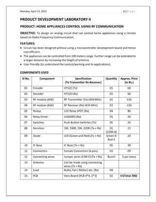
  • 1. Monday, April 13, 2015    1 | P a g e     PRODUCT DEVELOPMENT LABORATORY II  PRODUCT: HOME APPLIANCES CONTROL USING RF COMMUNICATION  OBJECTIVE: To design an analog circuit that can control home appliances using a remote  based on Radio Frequency Communication.  FEATURES:    Circuit has been designed without using a microcontroller development board and hence  cost efficient.   The appliances can be controlled from 100 meters range. Further range can be extended to  a larger distance by increasing the height of antenna.   User friendly (to understand the control/working and its applications).    COMPONENTS USED  Sl No.  Component  Specification  (Tx‐Transmitter Rx‐Receiver)  Quantity  Approx. Price (in Rs.)  01  Encoder  HT12E (Tx)  01  60  02  Decoder  HT12D (Rx)  01  60  03  RF module (ASK)  RF Transmitter (Tx) (434 MHz)  01  110  04  RF module (ASK)  RF Receiver (Rx) (434 MHz)  01  110  05  Relays   12V Relay SPDT (Rx)   04  80  06  Relay Driver  ULN2003 (Rx)  01  20  07  Switches  Push Button Switches (Tx)  05  25  08  Resistors  1M, 330R, 33K, 220R (Tx + Rx)  01  (220R‐4)  15  09  Diode  LED (Green and Red) (Tx + Rx)  Green‐4  Red‐2  20  10  IC Base  IC Base (Tx + Rx)  05  30  11   Connectors  Female Connectors (4 pins)  03  09  12  Connecting wires  Jumper wires (F/M‐F) (Tx + Rx)  Bunch  5 per piece  13  Antenna  Can be made using connecting  wires (Tx + Rx)      14  Load  Bulbs, Fan ( Motor) etc. (Rx)  04    15  PCB   Vero Board (PCB 4*4, 2*3)  02  80(Total 700)         
  • 2. Monday, April 13, 2015    2 | P a g e     BLOCK DIAGRAM                                              Output of the decoder is connected to the relay driver which is then fed to relays that  control the loads.         
  • 3. Monday, April 13, 2015    3 | P a g e     COMPONENTS DESCRIPTION  HT12E  The 212  encoders are a series of CMOS LSIs for remote control system  applications. They are capable of encoding information which consists of  N address bits and 12‐N data bits. Each address/data input can be set to  one  of  the  two  logic  states.  The  programmed  addresses/data  are  transmitted  together  with  the  header  bits  via  an  RF  or  an  infrared  transmission medium upon receipt of a trigger signal. The capability to  select  a  TE  trigger  on  the  HT12E  further  enhances  the  application  flexibility of the 212  series of encoders.   Features  ‐ Operating voltage ‐ 2.4V‐12V for the HT12E.  ‐ Low power and high noise immunity CMOS technology.  ‐ Low standby current: 0.1 uA (typ.) at VDD = 5V.  ‐ Four words transmission for the HT12E.  ‐ Built‐in oscillator needs only 5% resistor.  ‐ Data code has positive polarity.  ‐ Minimal external components.  ‐ Pair with Holtek’s 212  series of decoders.  ‐ 18‐pin DIP, 20‐pin SOP package.  HT12D  The 212  decoders are a series of CMOS LSIs for remote control system  applications. They are paired with Holtek’s 212  series of encoders (refer to  the encoder/decoder cross reference table). For proper operation, a pair  of encoder/decoder with the same number of addresses and data format  should be chosen. The decoders receive serial addresses and data from a  programmed 212  series of encoders that are transmitted by a carrier using  an RF or an IR transmission medium. They compare the serial input data  three  times  continuously  with  their  local  addresses.  If  no  error  or  unmatched codes are found, the input data codes are decoded and then  transferred to the output pins. The VT pin also goes high to indicate a valid  transmission.  The  212   series  of  decoders  are  capable  of  decoding  informations that consist of N bits of address and 12‐N bits of data. Of this  series, the HT12D is arranged to provide 8 address bits and 4 data bits.  Features  ‐ Operating voltage: 2.4V~12V.  ‐ Low power and high noise immunity CMOS technology.  ‐ Low standby current.  ‐ Capable of decoding 12 bits of information.  ‐ Binary address setting.   
  • 4. Monday, April 13, 2015    4 | P a g e     ‐ Received codes are checked 3 times.  ‐ Address/Data number combination.  ‐ HT12D: 8 address bits and 4 data bits.  ‐ Built‐in oscillator needs only 5% resistor.  ‐ Valid transmission indicator.  ‐ Easy interface with an RF or an infrared transmission medium.  ‐ Minimal external components.  ‐ Pair with Holtek’s 212  series of encoders.  ‐ 18‐pin DIP, 20‐pin SOP package.  RF ASK Module (434 MHz)   The RF module, as the name suggests, operates at Radio Frequency. The  corresponding frequency range varies between 30 kHz & 300 GHz. In this  RF system, the digital data is represented as variations in the amplitude  of  carrier  wave.  This  kind  of  modulation  is  known  as  Amplitude  Shift  Keying (ASK).  Why RF is preferred over IR?  Transmission  through  RF  is  better  than  IR  (infrared)  because  of  many  reasons.   ‐ Firstly, signals through RF can travel through larger distances making  it suitable for long range applications.   ‐ Also, while IR mostly operates in line‐of‐sight mode, RF signals can  travel  even  when  there  is  an  obstruction  between  transmitter  &  receiver.  ‐  Next,  RF  transmission  is  more  strong  and  reliable  than  IR  transmission.   ‐ RF communication uses a specific frequency unlike IR signals which  are affected by other IR emitting sources.  This RF module comprises of an RF Transmitter and an RF Receiver. The  transmitter/receiver (Tx/Rx) pair operates at a frequency of 434 MHz. An  RF transmitter receives serial data and transmits it wirelessly through RF  through its antenna connected at pin4. The transmission occurs at the  rate of 1Kbps ‐ 10Kbps.The transmitted data is received by an RF receiver  operating at the same frequency as that of the transmitter.  The RF module is often used along with a pair of encoder/decoder. The  encoder is used for encoding parallel data for transmission feed while  reception is decoded by a decoder. HT12E‐HT12D, HT640‐HT648, etc. are  some commonly used encoder/decoder pair ICs.       
  • 5. Monday, April 13, 2015    5 | P a g e     RELAY  A  relay  is  an  electrically  operated  switch.  Many  relays  use  an electromagnet to mechanically operate a switch, but other operating  principles are also used, such as solid‐state relays. Relays are used where  it is necessary to control a circuit by a low‐power signal (with complete  electrical  isolation  between  control  and  controlled  circuits),  or  where  several circuits must be controlled by one signal. A relay switches one or  more poles, each of whose contacts can be thrown by energizing the coil.  Normally‐open  (NO)  contacts  connect  the  circuit  when  the  relay  is  activated; the circuit is disconnected when the relay is inactive. It is also  called a "Form A" contact or "make" contact. NO contacts may also be  distinguished as "early‐make" or "NOEM", which means that the contacts  close before the button or switch is fully engaged. Normally‐closed (NC)  contacts disconnect the circuit when the relay is activated; the circuit is  connected when the relay is inactive. It is also called a "Form B" contact  or "break" contact. NC contacts may also be distinguished as "late‐break"  or "NCLB", which means that the contacts stay closed until the button or  switch is fully disengaged. SPDT ‐ Single Pole Double Throw, a common  terminal connects to either of two others. Including two for the coil, such  a relay has five terminals in total.   RELAY DRIVER ULN2003A  The  ULN2003A  is  a  high‐voltage,  high‐current  Darlington  transistor  array.  It  consists of seven NPN Darlington pairs that feature high‐voltage outputs with  common‐cathode fly back diodes for switching inductive loads. The drivers can  be  paralleled for  higher  current capability, even stacking one  chip on  top of  another, both electrically and physically has been done. Generally it can also be  used for interfacing with stepper motor, where the motor requires high ratings  which cannot be provided by other interfacing devices.  Features   500 mA rated collector current (single output)   50 V output   Includes output fly back diodes   Inputs compatible with various types of logic  Typical  usage  of  the  ULN2003A  is  to  drive  relays,  lamp  and  LED  displays or stepper motors Logic buffers, Line drivers, Hammer driver.           
  • 6. Monday, April 13, 2015    6 | P a g e     CIRCUIT DIAGRAM                                      TRANSMITTER             RECEIVER             
  • 7. Monday, April 13, 2015    7 | P a g e     WORKING  This circuit utilizes the RF module (Tx/Rx) for making a wireless remote, which could be used  to drive an output from a distant place. RF module, as the name suggests, uses radio frequency  to send signals. These signals are transmitted at a particular frequency and a baud rate. A  receiver can receive these signals only if it is configured for that frequency. A four channel  encoder/decoder pair has also been used in this system. The input signals, at the transmitter  side, are taken through four switches while the outputs are monitored on a set of four LEDs  corresponding to each input switch. The circuit can be used for designing Remote Appliance  Control system. The outputs from the receiver can drive corresponding relays connected to  any household appliance.  This radio frequency (RF) transmission system employs Amplitude Shift Keying (ASK) with  transmitter/receiver (Tx/Rx) pair operating at 434 MHz. The transmitter module takes serial  input and transmits these signals through RF. The transmitted signals are received by the  receiver module placed away from the source of transmission. The system allows one way  communication between two nodes, namely, transmission and reception. The RF module has  been used in conjunction with a set of four channel encoder/decoder ICs. Here HT12E &  HT12D  have  been  used  as  encoder  and  decoder  respectively.  The  encoder  converts  the  parallel inputs (from the remote switches) into serial set of signals. These signals are serially  transferred through RF to the reception point. The decoder is used after the RF receiver to  decode the serial format and retrieve the original signals as outputs. These outputs can be  observed on corresponding LEDs.  Encoder IC (HT12E) receives parallel data in the form of address bits and control bits. The  control signals from remote switches along with 8 address bits constitute a set of 12 parallel  signals.  The  encoder  HT12E  encodes  these  parallel  signals  into  serial  bits.  Transmission  is  enabled by providing ground to pin14 which is active low. The control signals are given at pins  10‐13 of HT12E. The serial data is fed to the RF transmitter through pin17 of HT12E.  Transmitter, upon receiving serial data from encoder IC (HT12E), transmits it wirelessly to the  RF receiver. The receiver, upon receiving these signals, sends them to the decoder IC (HT12D)  through pin2. The serial data is received at the data pin (DIN, pin14) of HT12D. The decoder  then retrieves the original parallel format from the received serial data.  When no signal is received at data pin of HT12D, it remains in standby mode and consumes  very less current (less than 1μA) for a voltage of 5V. When signal is received by receiver, it is  given to DIN pin (pin14) of HT12D. On reception of signal, oscillator of HT12D gets activated.  IC HT12D then decodes the serial data and checks the address bits three times. If these bits  match with the local address pins (pins 1‐8) of HT12D, then it puts the data bits on its data  pins (pins 10‐13) and makes the VT pin high. An LED is connected to VT pin (pin17) of the  decoder. This LED works as an indicator to indicate a valid transmission. The corresponding  output is thus generated at the data pins of decoder IC. A signal is sent by lowering any or all  
  • 8. Monday, April 13, 2015    8 | P a g e     the pins 10‐13 of HT12E and corresponding signal is received at receiver’s end (at HT12D).  Address bits are configured by using the by using the first 8 pins of both encoder and decoder  ICs. To send a particular signal, address bits must be same at encoder and decoder ICs. By  configuring the address bits properly, a single RF transmitter can also be used to control  different RF receivers of same frequency.   To summarize, on each transmission, 12 bits of data is transmitted consisting of 8 address bits  and 4 data bits. The signal is received at receiver’s end which is then fed into decoder IC. If  address bits get matched, decoder converts it into parallel data and the corresponding data  bits get lowered which could be then used to drive the LEDs.   Amplitude Shift Keying (ASK)  It  is  a  form  of  amplitude  modulation  that  represents  digital  data  as  variations  in  the amplitude of a carrier wave. In an ASK system, the binary symbol 1 is represented by  transmitting a fixed‐amplitude carrier wave and fixed frequency for a bit duration of T seconds.  If the signal value is 1 then the carrier signal will be transmitted; otherwise, a signal value of 0  will be transmitted.  Antenna Specification  ‐ The recommended length of the antenna is 17cm.  ‐ Coiling the antenna up will shorten the range.   ‐ For best reception mount it vertical and on a suitable ground plane, (a conducting surface)  as high as one can manage.     IMPLEMENTATION AND TESTING  The circuit is simulated using NI Multisim and the transmitter and receiver circuits were  tested  on  breadboard.  The  final  circuit  was  implemented  on  Vero‐board  by  manual  Soldering. After soldering the components on to the PCB, the boards were thoroughly cleaned  for removing any residual flux and wire leads. All the components are checked for their values  and proper orientation if applicable. Before ICs were inserted into the sockets, power was  applied to the board and voltages were measured at the IC power points. Other DC voltages  were also checked if possible. Then power was removed from the board, and ICs were inserted  into  the  sockets,  checking  the  proper  orientation.  Power  was  again  applied  to  the  board  expected  voltages  and  signals  were  monitored.  The  supply  voltages  were  monitored  and  verified. Working was tested and the product was completed.         
  • 9. Monday, April 13, 2015    9 | P a g e     APPLICATIONS   Radio remote control is used to control distance objects using a variety of radio signals  transmitted by the remote control device. As a complementary method to infrared remote  controls,  the  radio  remote  control  is  used  with  electric  garage  door  or  gate  openers,  automatic barrier systems, burglar alarms and industrial automation systems.   Home appliances control and industrial applications   RF is used in jamming circuit for military purposes.   A remote controlled device primarily saves a lot of time and energy. Its significance in  today’s world is immense when people don’t have to unnecessarily waste their time in  operating the appliances by being near to the appliance. They can operate it while they’re  engrossed in whatever task they’re doing and don’t have to bother leaving it in between.    The remote control can extend up to a long distance depending on the frequency used  and the efficiency of the circuit. It is an advantage that it can be operated from distances.    Tediousness of operating the appliance in its close proximity is done away with. The circuit  has the advantages that it can be easily implemented using easily available and low cost  components. The maintenance is also easy.   Advantages  ‐ Highly Sensitive  ‐ Very low noise  ‐ Low cost and reliable circuit  ‐ The appliances can be controlled from 100 meters range. Further range can be extended  to a larger distance by increasing the height of antenna.  ‐ Can handle heavy loads up to 7 Amperes.     CONCLUSION  The product to demonstrate the remote controlled operation of multiple home appliances is  designed.                 
  • 10. Monday, April 13, 2015    10 | P a g e        REFERENCES      1. http://arif‐ece.blogspot.com/2010/05/tv‐remote‐controlled‐home‐appliance.html   2. http://arif‐ece.blogspot.com/2010_05_01_archive.html   3. http://www.circuitstoday.com/category/remote‐circuits   4. http://www.satsleuth.com/schematics.htm   5. http://www.printsasia.com/book/Electronic‐Projects‐for‐Beginners‐Using‐Easily‐ AvailableElectronic‐Components‐with‐A‐Primer‐on‐Basic‐8122301525‐9788122301526   6. http://www.dapj.net/hobby/?paged=2   7. http://extremeelectronics.co.in/