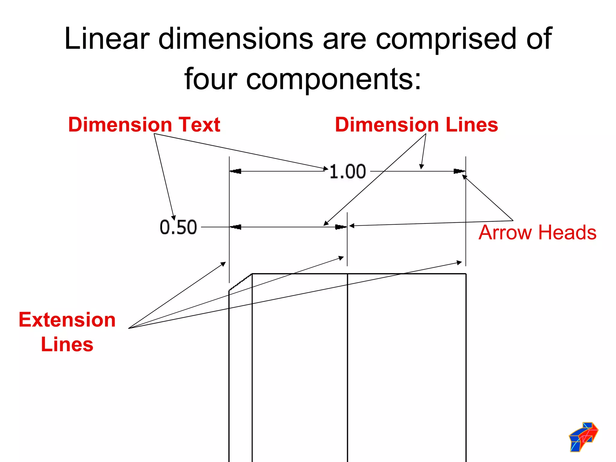
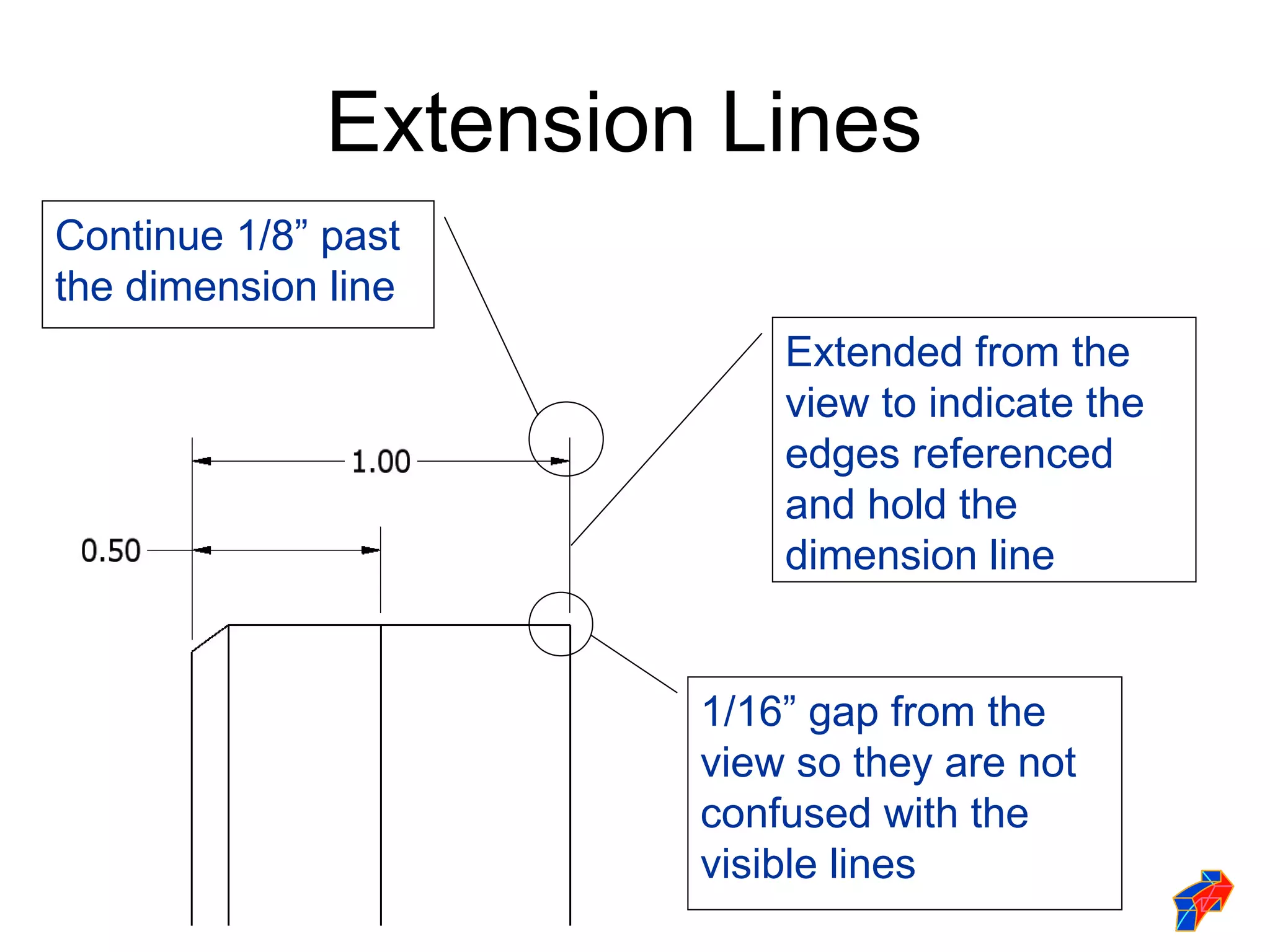
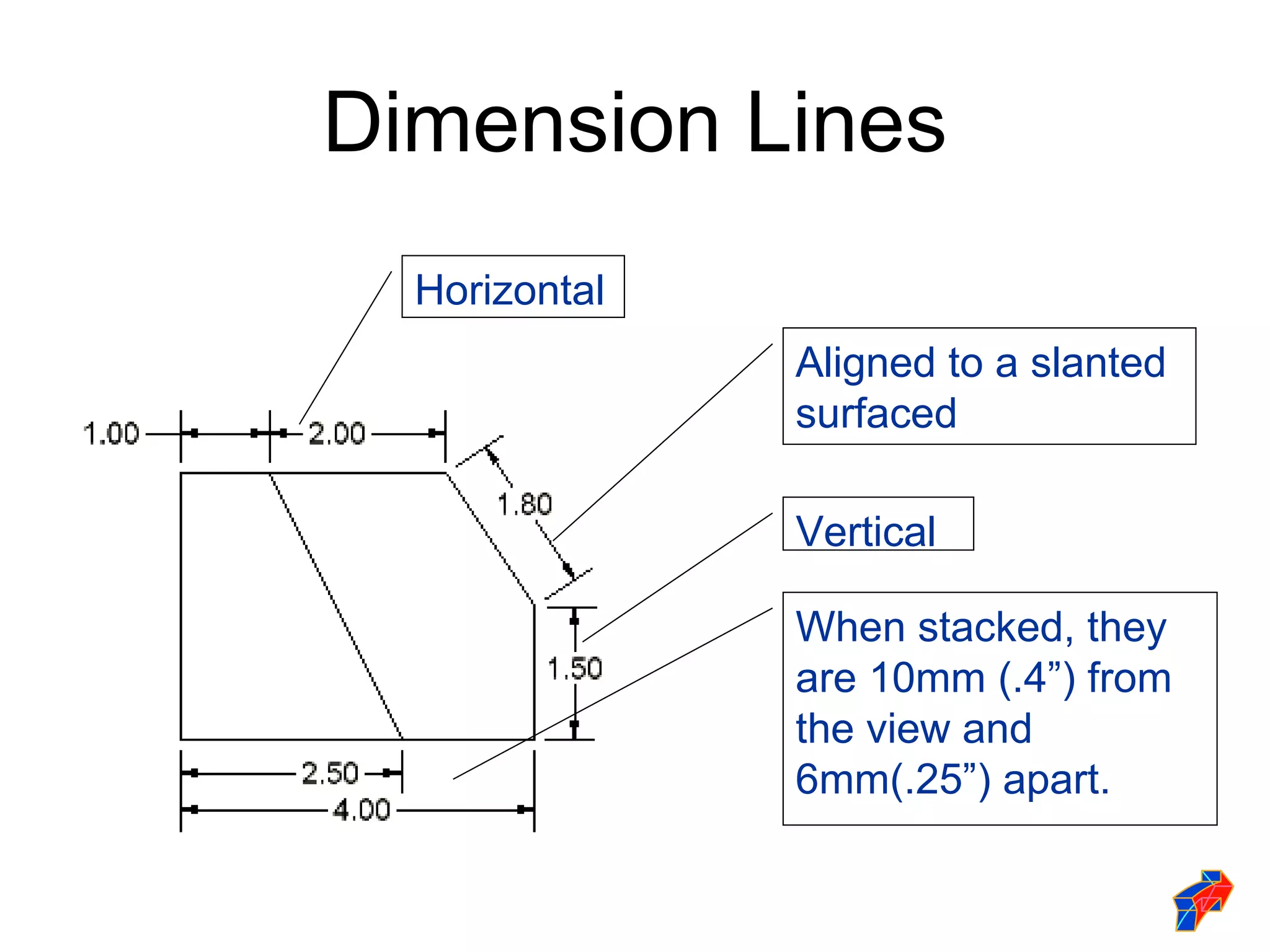
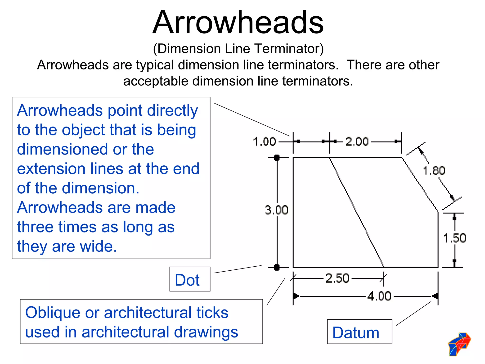
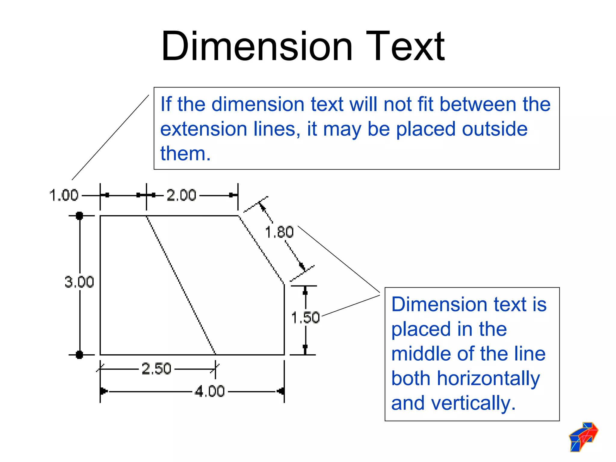
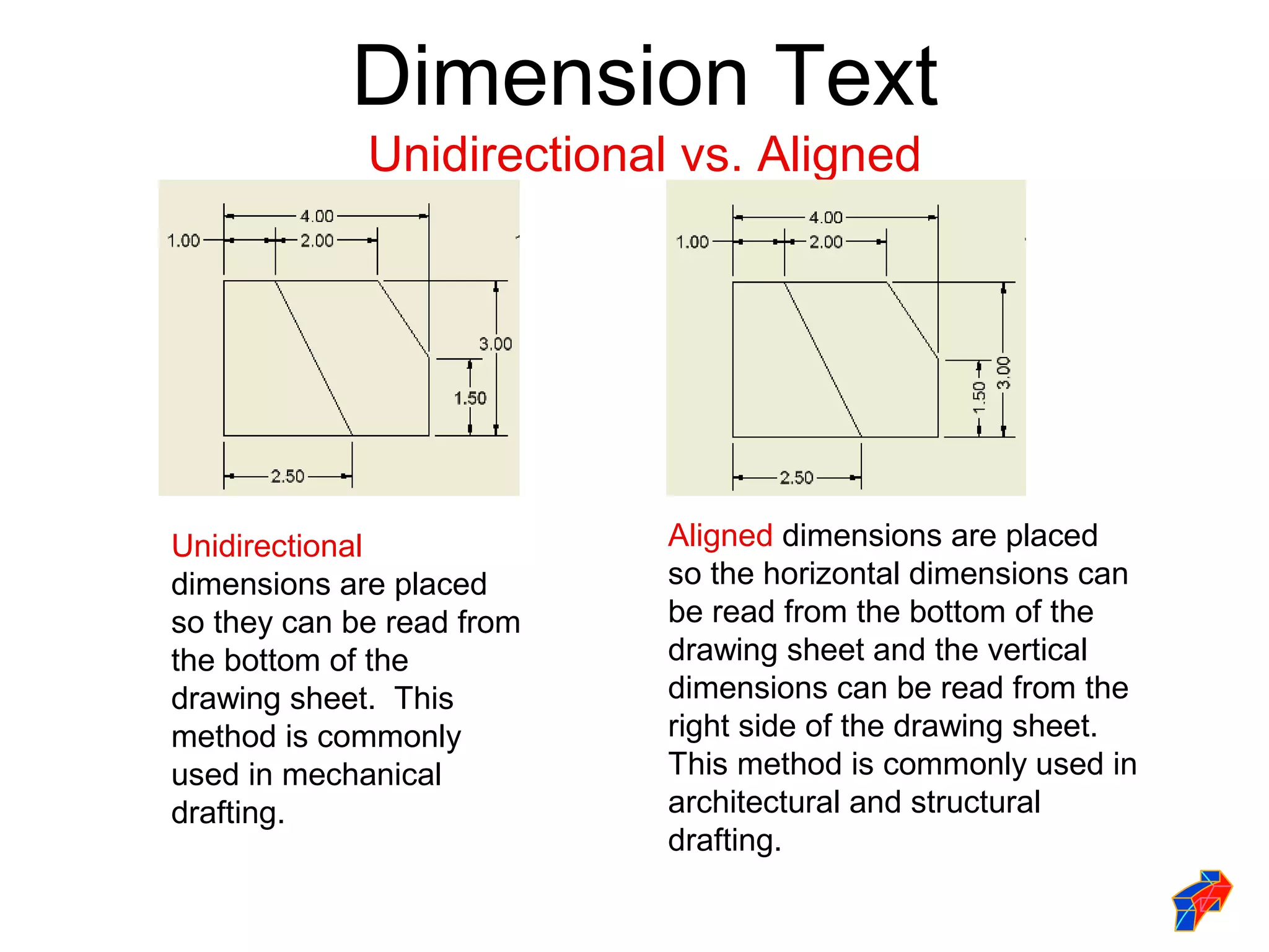
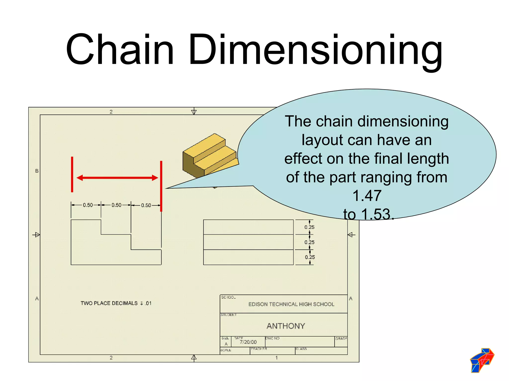
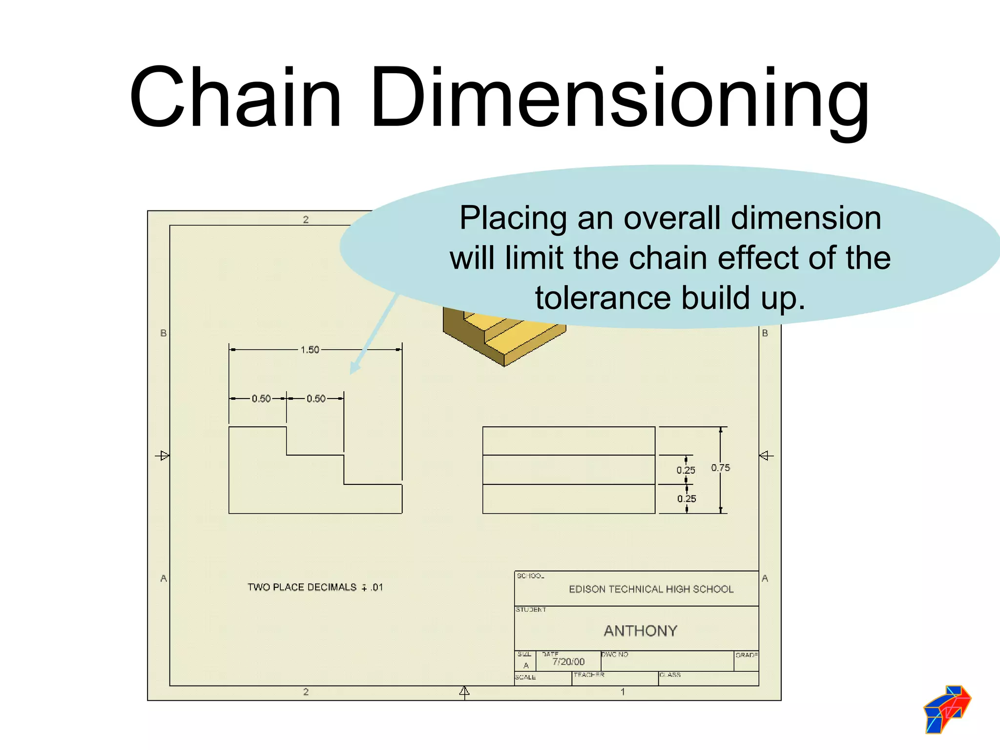
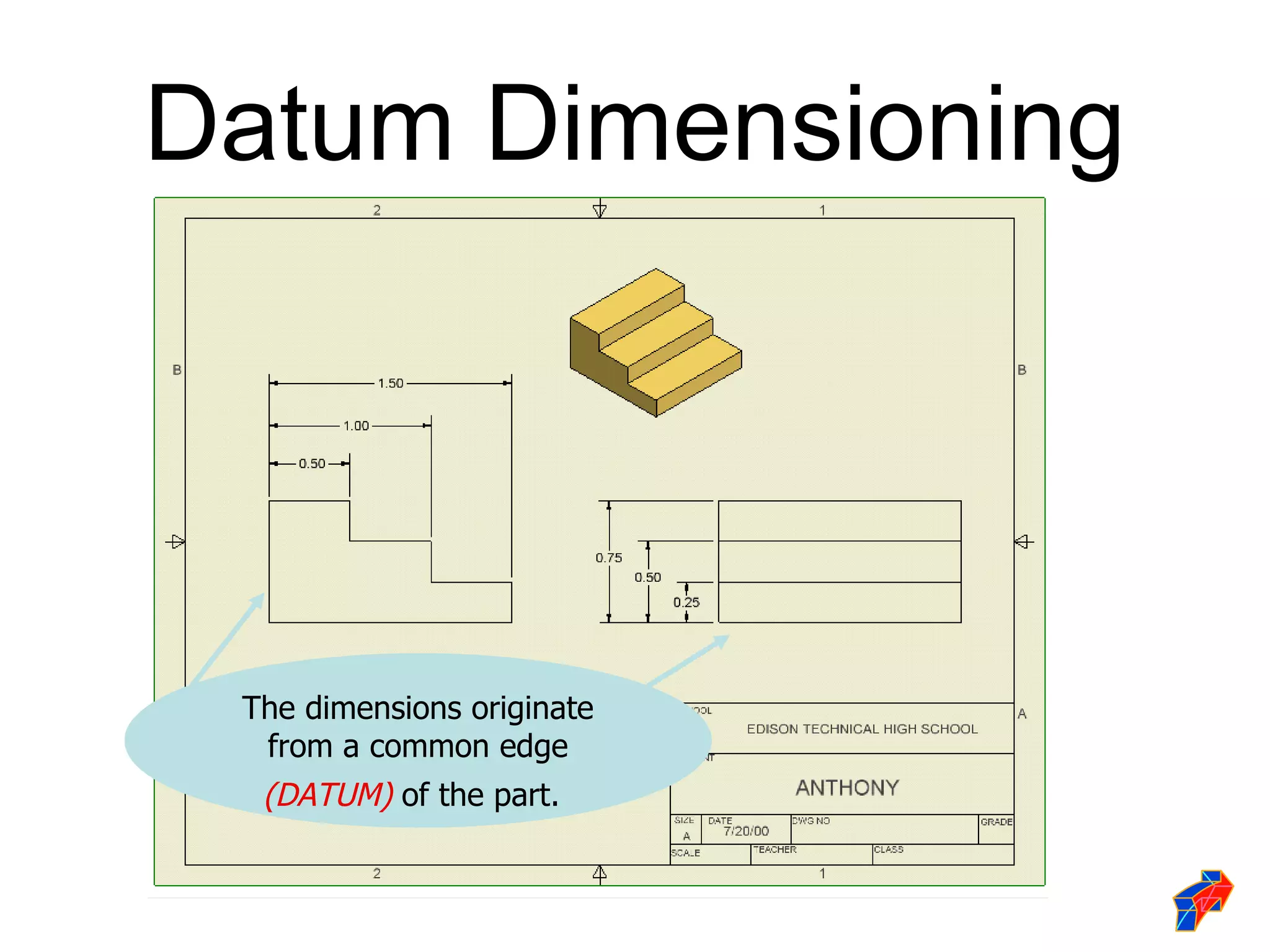
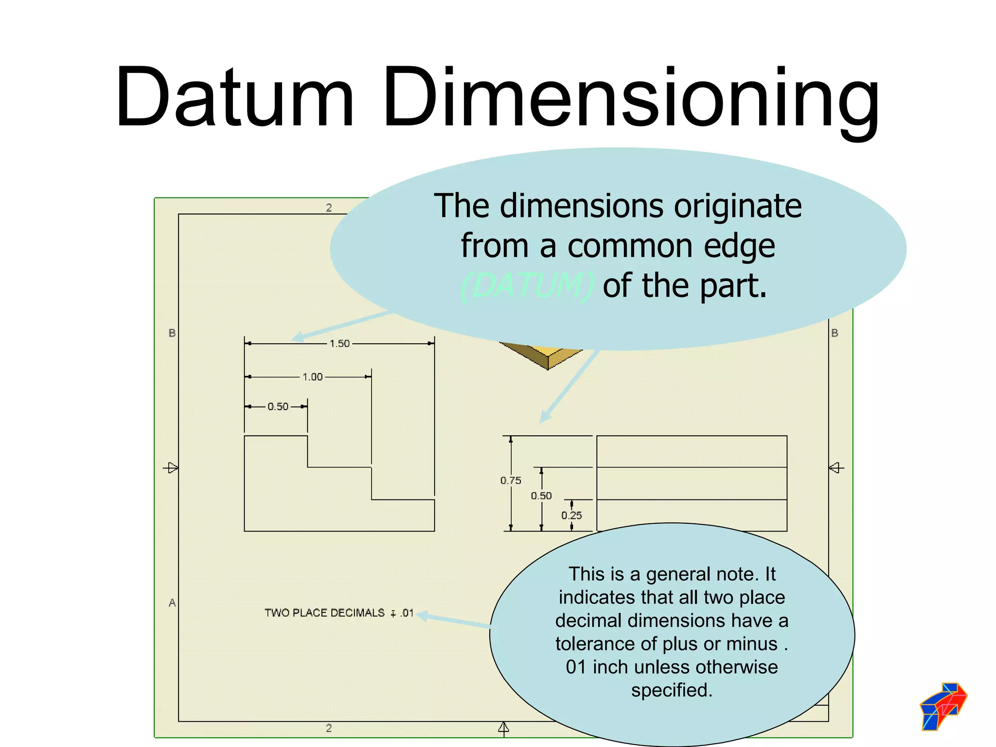
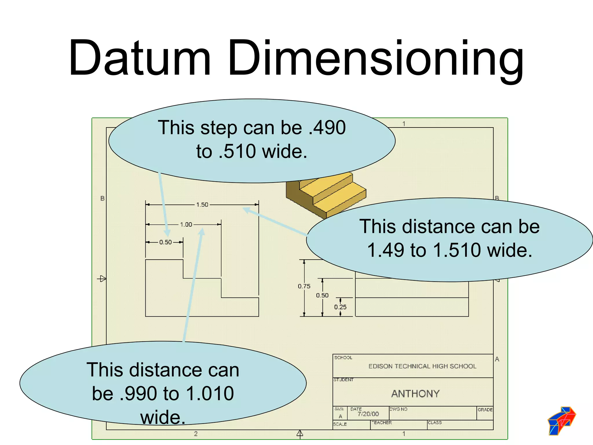
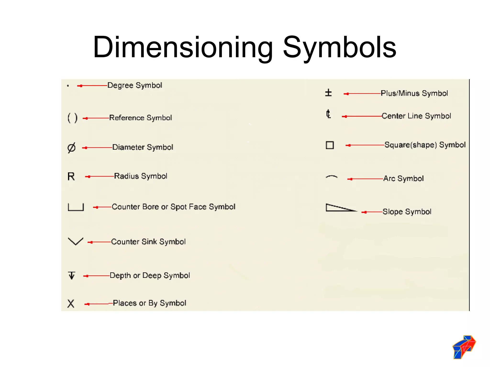
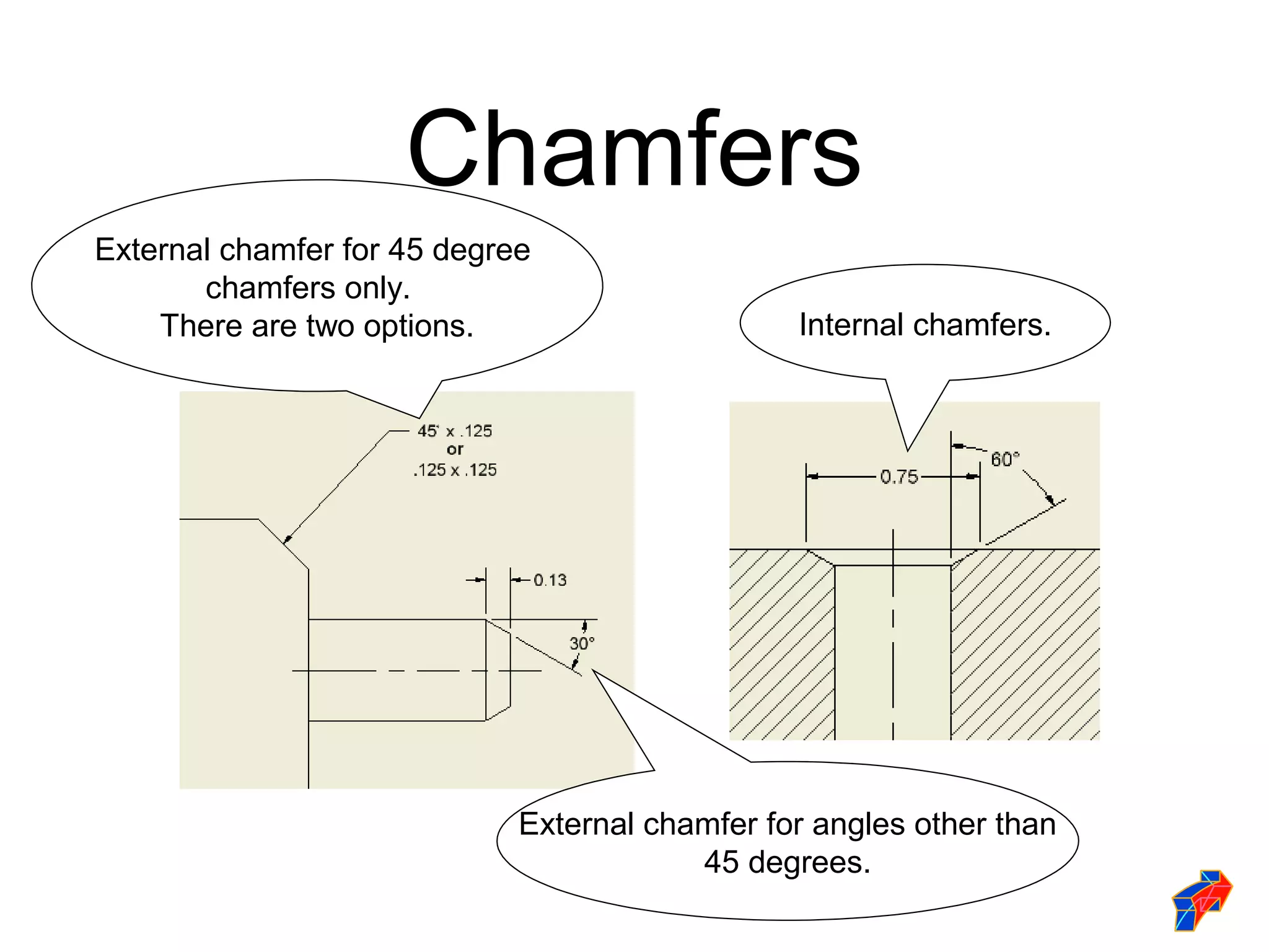
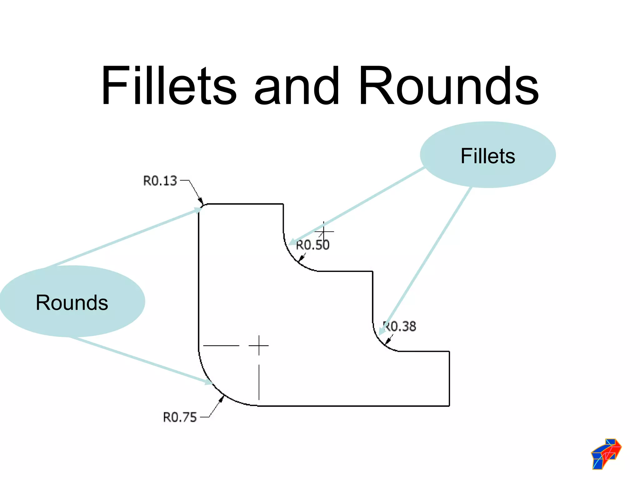
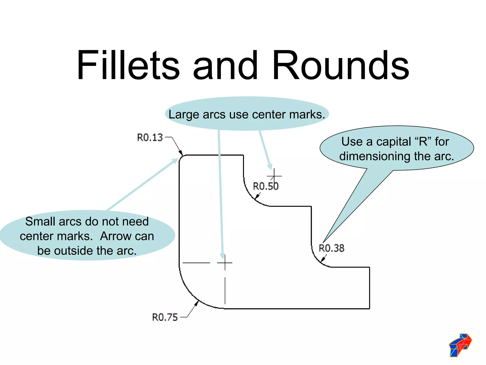
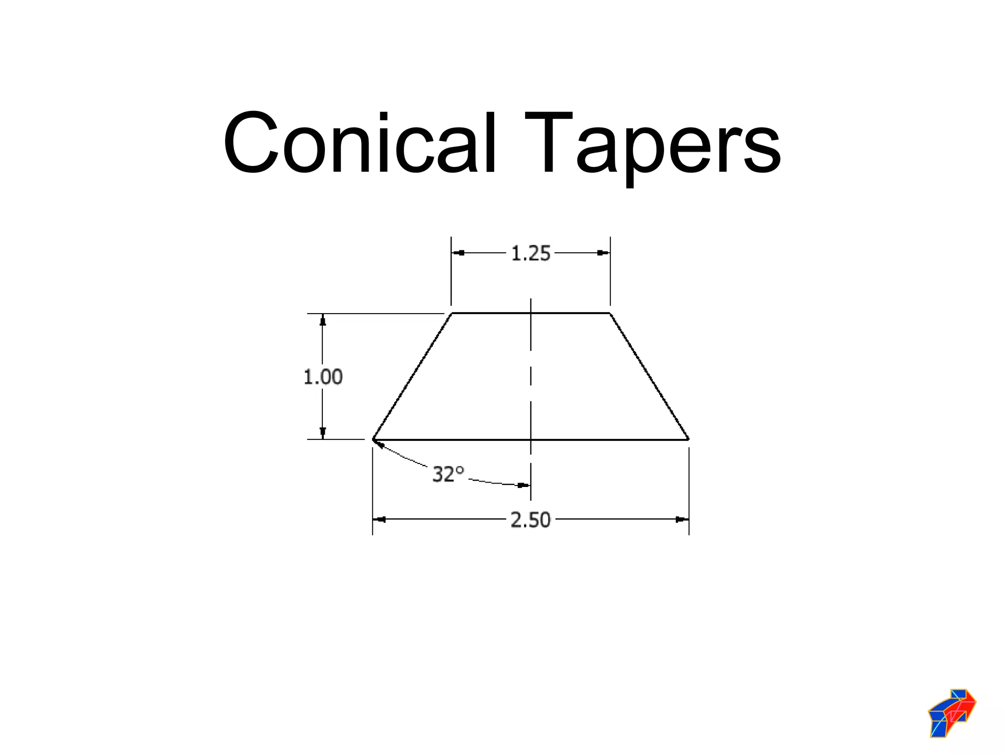
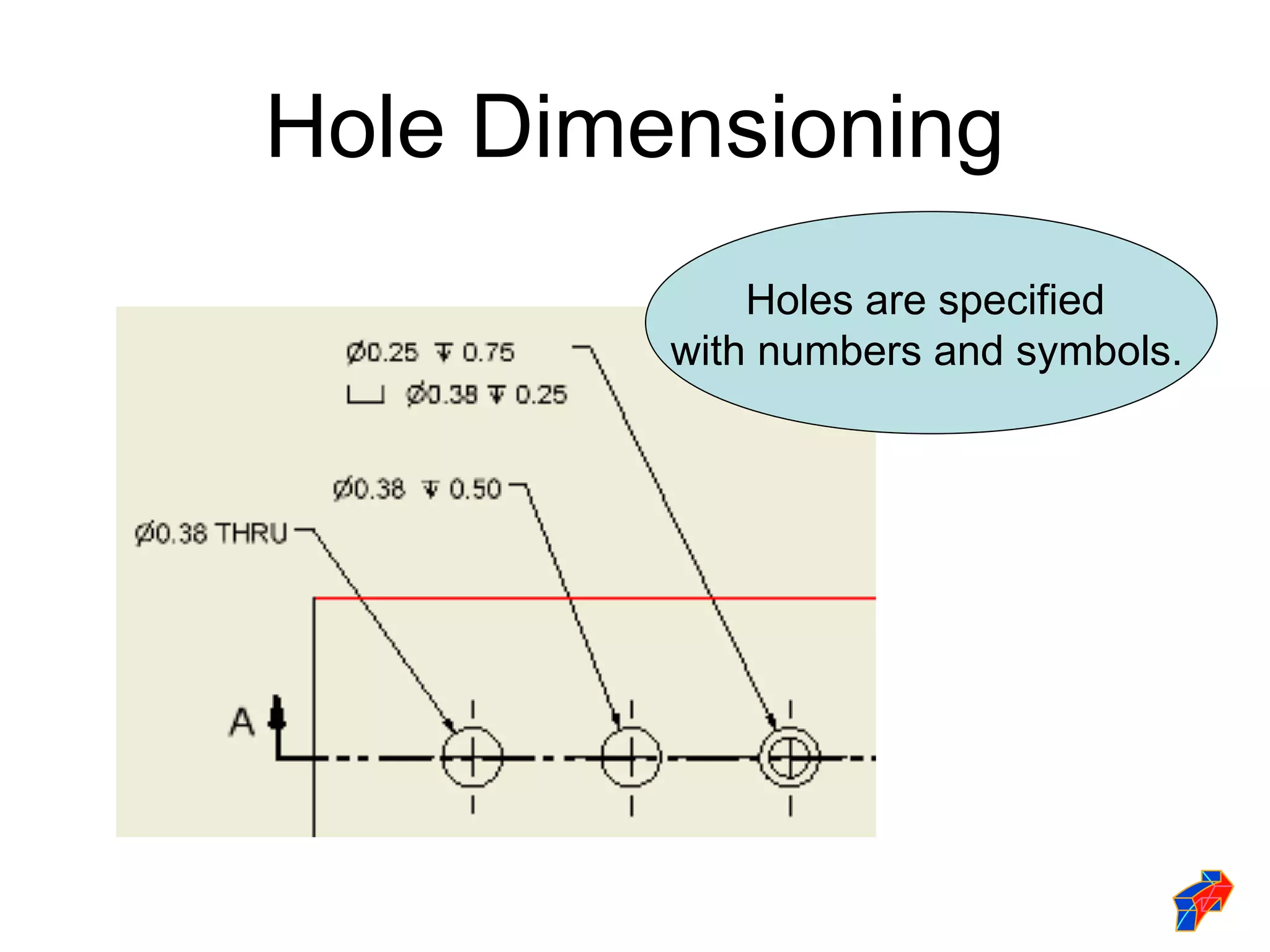
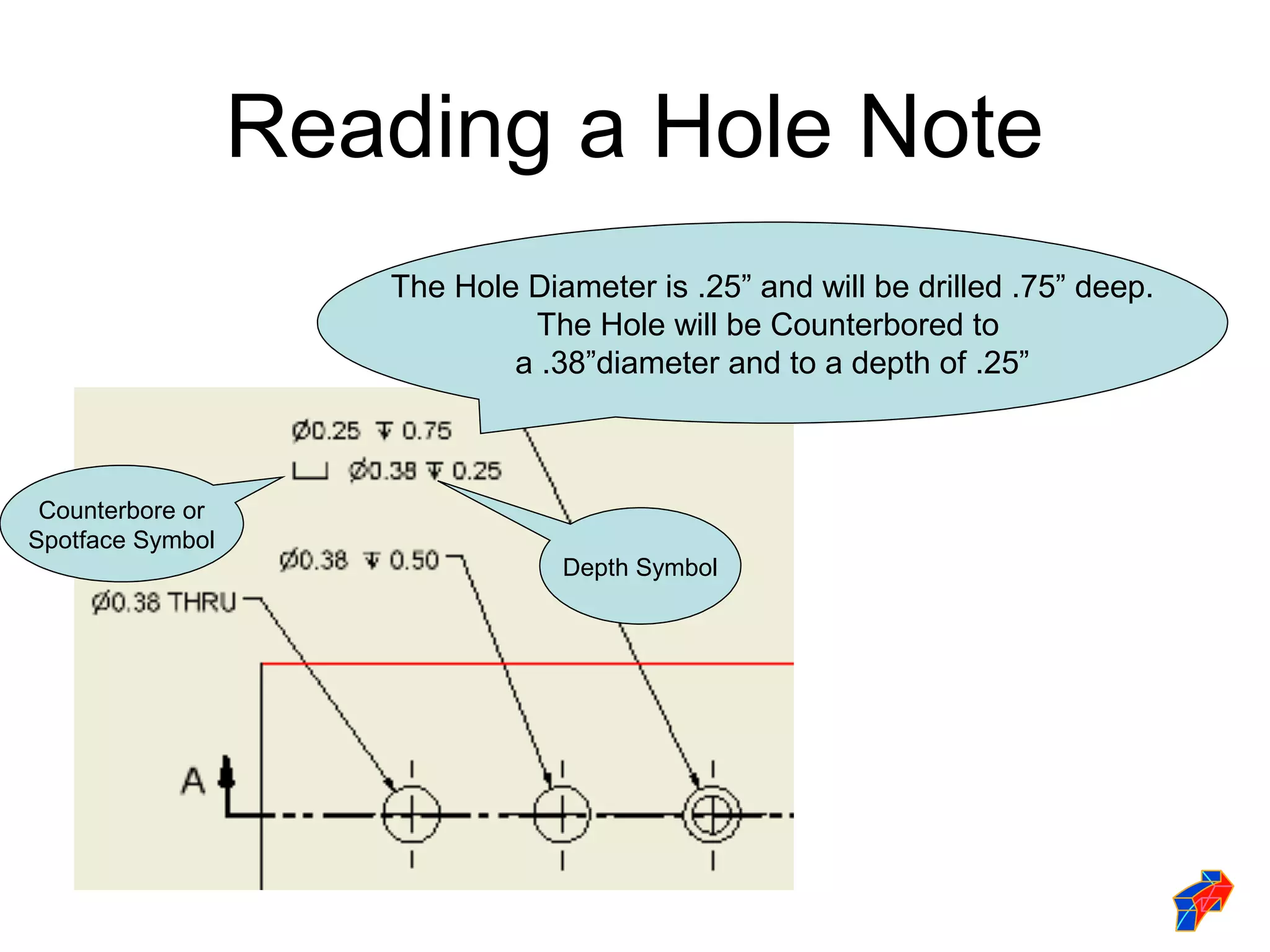
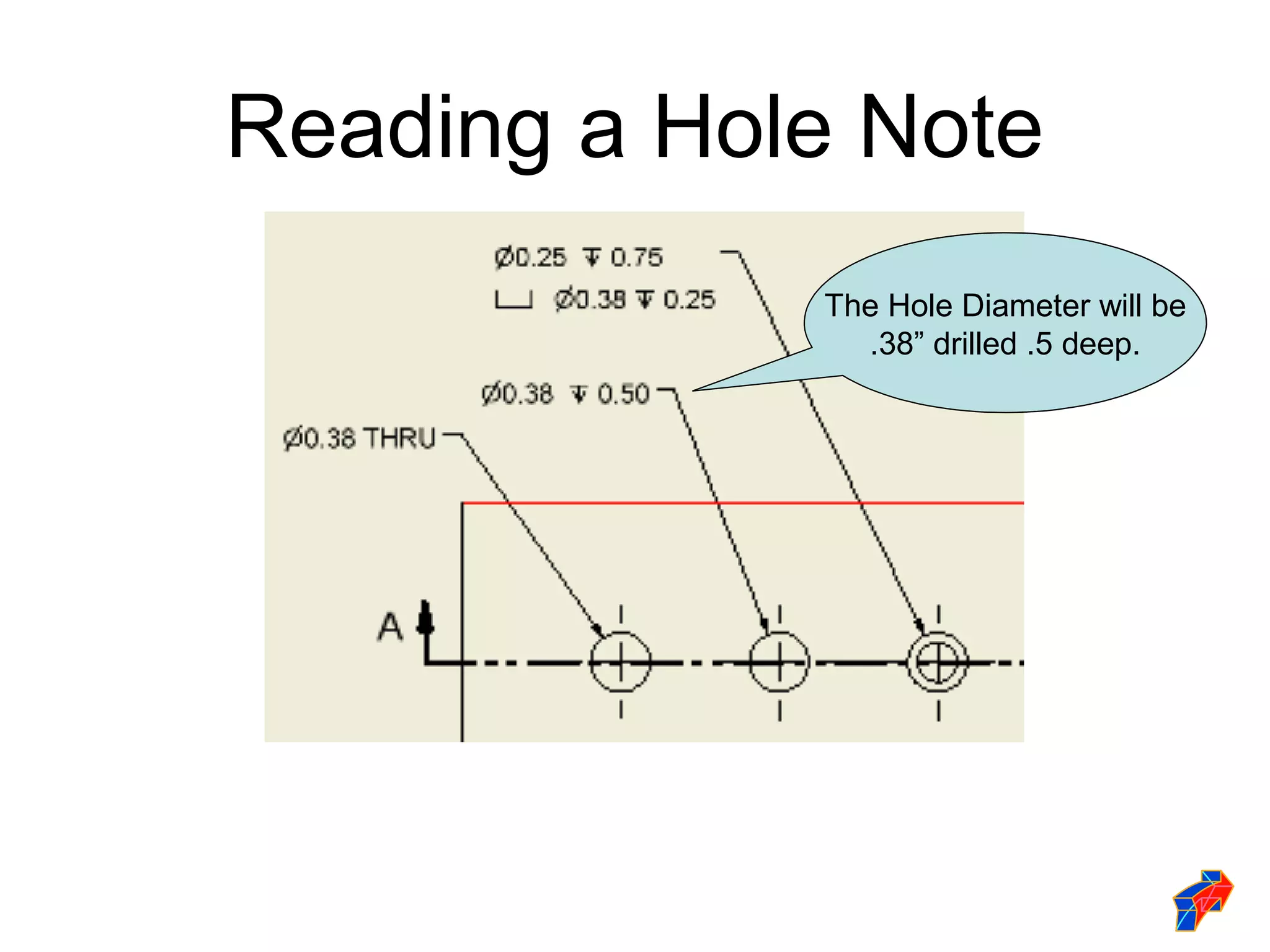
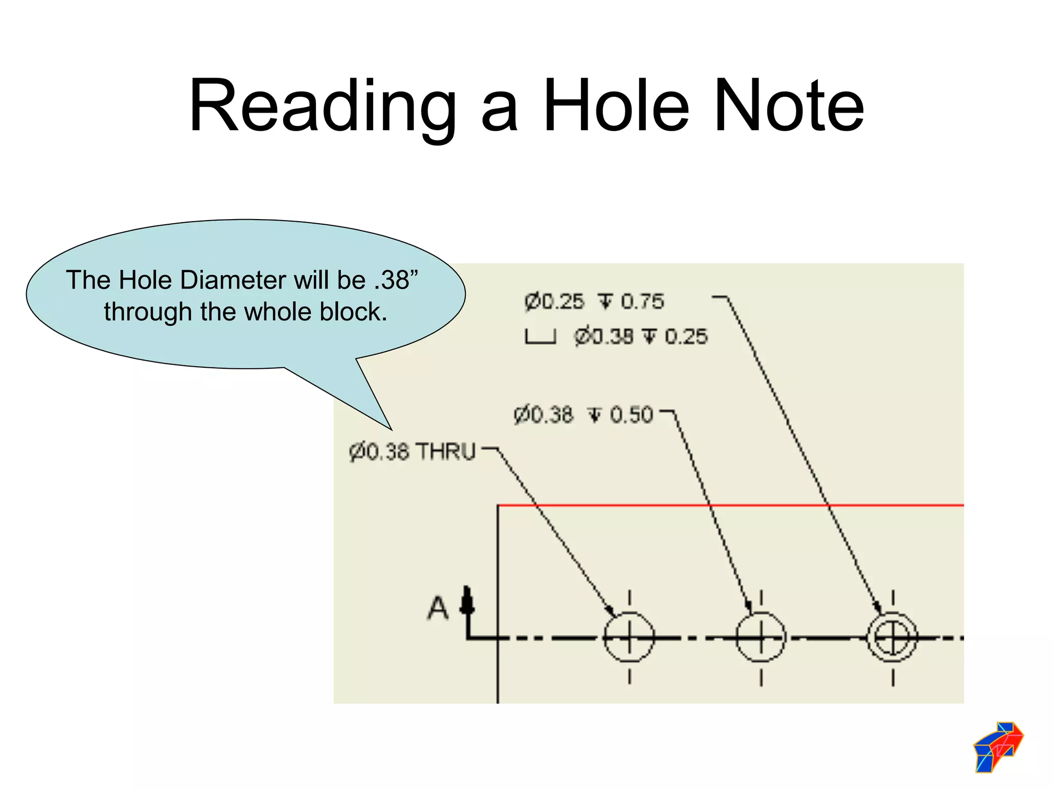
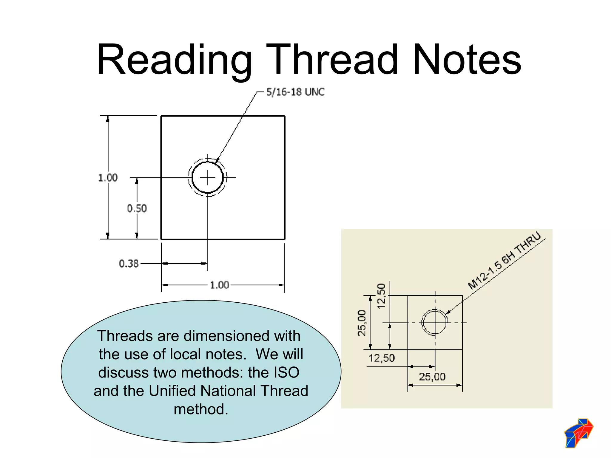
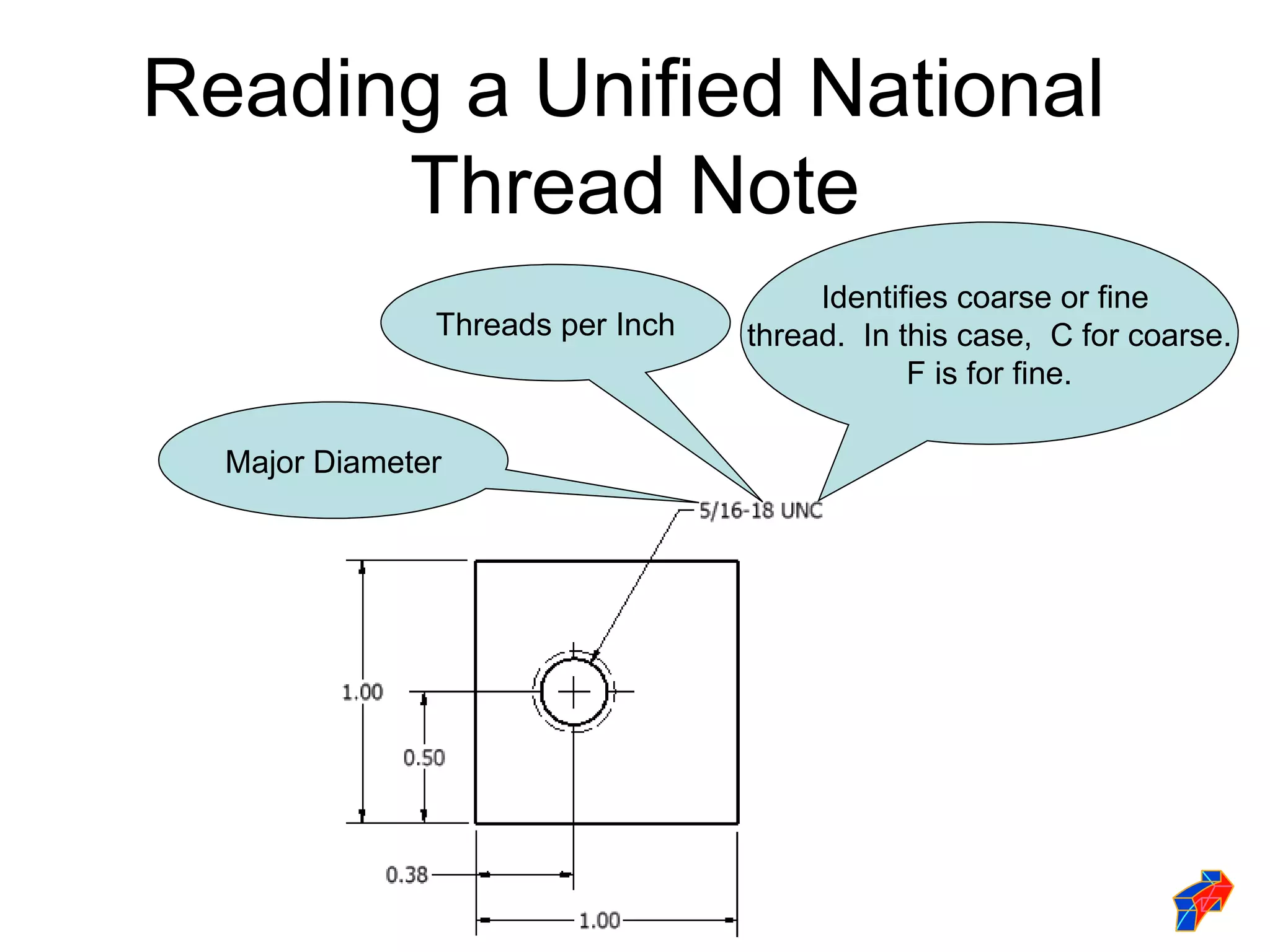
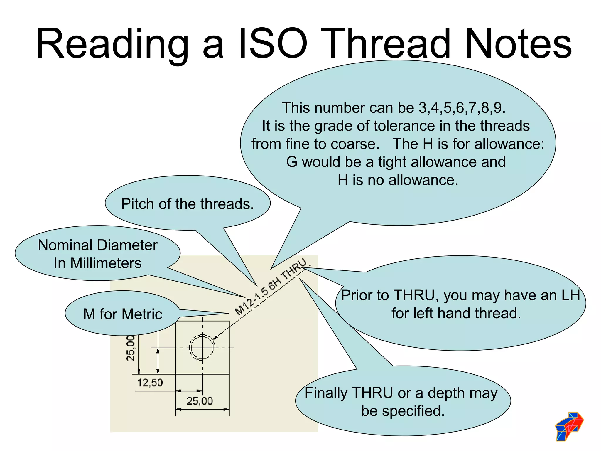
Forging new generations of engineers
Dimensioning
 Standards
Rules and Practices
 Accurate dimensioning is one of the most
  demanding undertakings when designing parts.

 Use the checklist to insure you have followed the
  basic dimensioning rules.

 Keep in mind there may be a case where the
  need to break a standard could occur to give
  clarity to the part and manufacturer.
Standards
 In order for the drawings to be dimensioned
  so that all people can understand them, we
  need to follow standards that every company
  in the world must follow. Standards are
  created by these organizations:
   -ANSI                -MIL
   -ISO                 -DOD
   -DIN                 -CEN
   -JIS
Standards Institutions
 ANSI - American National Standards Institute
  - This institute creates the engineering
  standards for North America.

 ISO - International Organization for
  Standardization - This is a world wide
  organization that creates engineering
  standards with approximately 100
  participating countries.
Standards Institutions
 DIN - Deutsches Institut für Normung - The
  German Standards Institute created many
  standards used world wide such as the
  standards for camera film.

 JIS - Japanese Industrial Standard - Created
  after WWII for Japanese standards.

 CEN - European Standards Organization
Standards Institutions
 The United States military has two organizations
  that develop standards.

   DOD - Department Of Defense
   MIL - Military Standard
Linear dimensions are comprised of
             four components:
    Dimension Text    Dimension Lines


                                   Arrow Heads


Extension
  Lines
Extension Lines
Continue 1/8” past
the dimension line
                           Extended from the
                           view to indicate the
                           edges referenced
                           and hold the
                           dimension line


                       1/16” gap from the
                       view so they are not
                       confused with the
                       visible lines
Dimension Lines
  Horizontal
               Aligned to a slanted
               surfaced

               Vertical

               When stacked, they
               are 10mm (.4”) from
               the view and
               6mm(.25”) apart.
Arrowheads
                    (Dimension Line Terminator)
  Arrowheads are typical dimension line terminators. There are other
               acceptable dimension line terminators.

Arrowheads point directly
to the object that is being
dimensioned or the
extension lines at the end
of the dimension.
Arrowheads are made
three times as long as
they are wide.

                        Dot

 Oblique or architectural ticks
 used in architectural drawings                   Datum
Dimension Text
If the dimension text will not fit between the
extension lines, it may be placed outside
them.


                           Dimension text is
                           placed in the
                           middle of the line
                           both horizontally
                           and vertically.
Dimensioning Methods
 Dimensions are represented on a drawing using
  one of two systems, unidirectional or aligned.
 The unidirectional method means all dimensions
  are read in the same direction.
 The aligned method means the dimensions are
  read in alignment with the dimension lines or
  side of the part, some read horizontally and
  others read vertically.
Dimension Text
             Unidirectional vs. Aligned


Unidirectional             Aligned dimensions are placed
dimensions are placed      so the horizontal dimensions can
so they can be read from   be read from the bottom of the
the bottom of the          drawing sheet and the vertical
drawing sheet. This        dimensions can be read from the
method is commonly         right side of the drawing sheet.
used in mechanical         This method is commonly used in
drafting.                  architectural and structural
                           drafting.
Types of Dimensions
 There are two classifications of dimensions: size
  and location.

 Size dimensions are placed in direct
  relationship to a feature to identify the specific
  size.
 Location dimensions are used to identify the
  relationship of a feature to another feature within
  an object.
Dimensioning Checklist
 Each dimension should be written clearly
  with only one way to be interpreted.
 A feature should be dimensioned only once.
 Dimension and extension lines should not
  cross.
 Each feature should be dimensioned.
 Dimension features or surfaces should be
  done to a logical reference point.
Dimension Checklist
 Dimension circles should have
  diameters and arcs with a radius.
 A center line should be extended and
  used as an extension line.
 Dimension features on a view should
  clearly show its true shape.
 Enough space should be provided to
  avoid crowding and misinterpretation.
Dimension Checklist
 Extension lines and object lines
  should not overlap.
 Dimensions should be placed outside
  the part.
 Center lines or marks should be used
  on all circles and holes.
Linear Dimensioning
 Dimensioning from feature to feature
  is known as Chain Dimensioning.. It
  is commonly used and easy to lay
  out. It does have possible
  consequences in the manufacturing
  of a part. Tolerances can
  accumulate, making the end product
  larger or smaller than expected.
Chain Dimensioning

             This is a general note. It
              indicates that all two
                   place decimal
               dimensions have a
               tolerance of plus or
              minus .01 inch unless
               otherwise specified.
Chain Dimensioning
Each of these steps
can range between .
       490”
  and .510” wide.
Chain Dimensioning
          The chain dimensioning
             layout can have an
          effect on the final length
          of the part ranging from
                     1.47
                   to 1.53.
Chain Dimensioning
       Placing an overall dimension
       will limit the chain effect of the
               tolerance build up.
Linear Dimensioning
 The accuracy of the final product is
  determined by the dimensions on the
  drawing. If all the dimensions originate
  from a common corner of the part, the
  object will be more accurate. This is
  referred to as Datum Dimensioning.
  Datums insure the tolerance or errors in
  manufacturing do not accumulate.
Datum Dimensioning


 The dimensions originate
  from a common edge
  (DATUM) of the part.
Datum Dimensioning
       The dimensions originate
        from a common edge
        (DATUM) of the part.


                 This is a general note. It
               indicates that all two place
              decimal dimensions have a
              tolerance of plus or minus .
                01 inch unless otherwise
                         specified.
Datum Dimensioning
       This step can be .490
           to .510 wide.


                               This distance can be
                                1.49 to 1.510 wide.


This distance can
be .990 to 1.010
      wide.
Dimensioning Symbols
Dimensioning Angles
 Angled surface may be dimensioned
  using coordinate method to specify
  the two location distances of the
  angle.
 Angled surfaces may also be
  dimensioned using the angular
  method by specifying one location
  distance and the angle.
Dimensioning Angles

Coordinate Method   Angular Method
Dimensioning Arcs and
           Circles
 Arcs and circles are dimensioned in views
  that show the arc or circle.
 Arcs are dimensioned with a leader to
  identify the radius; in some cases, a center
  mark is included.
 Circles should have a center mark and are
  dimensioned with a leader to identify the
  diameter.
Dimensioning Curved Features
          and Arcs
The arrow can be inside
     for small arcs.


                              Use a capital “R” for
                               dimensioning arcs.

  Small arcs do not need
 center marks. Arrow can
        be outside.


                           Large Arcs use center
                                  marks.
Diameters
A full circular object should be dimensioned
 using its diameter. Holes should use hole
                     notes.


                                                This specification
                                               calls for a hole with
                                                   a .5 diameter
                                                 and 1.00 deep.
Diameters
Cylindrical parts may show their diameters in this
 manner. Dimensioning on the right side view
             could be too crowded.


Note that the diameter symbol is used so it
 is not confused with a linear dimension.
Chords
    Chords may be dimensioned in one of
            the following ways.
Dimensioning Curved Features
 Points are placed along the contour
and are dimensioned from the datum.


                                       Datum
Reference Dimensions
 Designates more than one of the same feature.
      In this case, it is identifying there are
                two identical holes.
Chamfers
External chamfer for 45 degree
       chamfers only.
    There are two options.                      Internal chamfers.


                             External chamfer for angles other than
                                         45 degrees.
Fillets and Rounds
                   Fillets


Rounds
Fillets and Rounds
                          Large arcs use center marks.

                                                         Use a capital “R” for
                                                         dimensioning the arc.


 Small arcs do not need
center marks. Arrow can
   be outside the arc.
Conical Tapers
Slot Dimensioning
           The two methods
            shown on the left
           are the acceptable
              methods for
          dimensioning slotted
                 holes.
Dimensioning Radial
     Patterns
               Angles and radius values
             are used to locate the centers
              of radial patterned features,
                  such as the holes on
                        this plate.
Keyway and Keyseat
    Keyway   Keyseat
Keyways
           Keyway Dimensions

Shaft
Hole Dimensioning
             Holes are specified
         with numbers and symbols.
Reading a Hole Note
                     The Hole Diameter is .25” and will be drilled .75” deep.
                              The Hole will be Counterbored to
                             a .38”diameter and to a depth of .25”


 Counterbore or
Spotface Symbol
                                 Depth Symbol
Reading a Hole Note
             The Hole Diameter will be
               .38” drilled .5 deep.
Reading a Hole Note

The Hole Diameter will be .38”
  through the whole block.
Reading Thread Notes


Threads are dimensioned with
 the use of local notes. We will
 discuss two methods: the ISO
and the Unified National Thread
             method.
Reading a Unified National
      Thread Note
                                       Identifies coarse or fine
               Threads per Inch   thread. In this case, C for coarse.
                                              F is for fine.

  Major Diameter
Reading a ISO Thread Notes
                                      This number can be 3,4,5,6,7,8,9.
                                 It is the grade of tolerance in the threads
                               from fine to coarse. The H is for allowance:
                                      G would be a tight allowance and
                                              H is no allowance.
           Pitch of the threads.

Nominal Diameter
  In Millimeters

                                            Prior to THRU, you may have an LH
      M for Metric                                   for left hand thread.


                                       Finally THRU or a depth may
                                                be specified.

Dimensioning standards

  • 1.
  • 2.
  • 3.
    Rules and Practices Accurate dimensioning is one of the most demanding undertakings when designing parts.  Use the checklist to insure you have followed the basic dimensioning rules.  Keep in mind there may be a case where the need to break a standard could occur to give clarity to the part and manufacturer.
  • 4.
    Standards  In orderfor the drawings to be dimensioned so that all people can understand them, we need to follow standards that every company in the world must follow. Standards are created by these organizations: -ANSI -MIL -ISO -DOD -DIN -CEN -JIS
  • 5.
    Standards Institutions  ANSI- American National Standards Institute - This institute creates the engineering standards for North America.  ISO - International Organization for Standardization - This is a world wide organization that creates engineering standards with approximately 100 participating countries.
  • 6.
    Standards Institutions  DIN- Deutsches Institut für Normung - The German Standards Institute created many standards used world wide such as the standards for camera film.  JIS - Japanese Industrial Standard - Created after WWII for Japanese standards.  CEN - European Standards Organization
  • 7.
    Standards Institutions  TheUnited States military has two organizations that develop standards.  DOD - Department Of Defense  MIL - Military Standard
  • 8.
    Linear dimensions arecomprised of four components: Dimension Text Dimension Lines Arrow Heads Extension Lines
  • 9.
    Extension Lines Continue 1/8”past the dimension line Extended from the view to indicate the edges referenced and hold the dimension line 1/16” gap from the view so they are not confused with the visible lines
  • 10.
    Dimension Lines Horizontal Aligned to a slanted surfaced Vertical When stacked, they are 10mm (.4”) from the view and 6mm(.25”) apart.
  • 11.
    Arrowheads (Dimension Line Terminator) Arrowheads are typical dimension line terminators. There are other acceptable dimension line terminators. Arrowheads point directly to the object that is being dimensioned or the extension lines at the end of the dimension. Arrowheads are made three times as long as they are wide. Dot Oblique or architectural ticks used in architectural drawings Datum
  • 12.
    Dimension Text If thedimension text will not fit between the extension lines, it may be placed outside them. Dimension text is placed in the middle of the line both horizontally and vertically.
  • 13.
    Dimensioning Methods  Dimensionsare represented on a drawing using one of two systems, unidirectional or aligned.  The unidirectional method means all dimensions are read in the same direction.  The aligned method means the dimensions are read in alignment with the dimension lines or side of the part, some read horizontally and others read vertically.
  • 14.
    Dimension Text Unidirectional vs. Aligned Unidirectional Aligned dimensions are placed dimensions are placed so the horizontal dimensions can so they can be read from be read from the bottom of the the bottom of the drawing sheet and the vertical drawing sheet. This dimensions can be read from the method is commonly right side of the drawing sheet. used in mechanical This method is commonly used in drafting. architectural and structural drafting.
  • 15.
    Types of Dimensions There are two classifications of dimensions: size and location.  Size dimensions are placed in direct relationship to a feature to identify the specific size.  Location dimensions are used to identify the relationship of a feature to another feature within an object.
  • 16.
    Dimensioning Checklist  Eachdimension should be written clearly with only one way to be interpreted.  A feature should be dimensioned only once.  Dimension and extension lines should not cross.  Each feature should be dimensioned.  Dimension features or surfaces should be done to a logical reference point.
  • 17.
    Dimension Checklist  Dimensioncircles should have diameters and arcs with a radius.  A center line should be extended and used as an extension line.  Dimension features on a view should clearly show its true shape.  Enough space should be provided to avoid crowding and misinterpretation.
  • 18.
    Dimension Checklist  Extensionlines and object lines should not overlap.  Dimensions should be placed outside the part.  Center lines or marks should be used on all circles and holes.
  • 19.
    Linear Dimensioning  Dimensioningfrom feature to feature is known as Chain Dimensioning.. It is commonly used and easy to lay out. It does have possible consequences in the manufacturing of a part. Tolerances can accumulate, making the end product larger or smaller than expected.
  • 20.
    Chain Dimensioning This is a general note. It indicates that all two place decimal dimensions have a tolerance of plus or minus .01 inch unless otherwise specified.
  • 21.
    Chain Dimensioning Each ofthese steps can range between . 490” and .510” wide.
  • 22.
    Chain Dimensioning The chain dimensioning layout can have an effect on the final length of the part ranging from 1.47 to 1.53.
  • 23.
    Chain Dimensioning Placing an overall dimension will limit the chain effect of the tolerance build up.
  • 24.
    Linear Dimensioning  Theaccuracy of the final product is determined by the dimensions on the drawing. If all the dimensions originate from a common corner of the part, the object will be more accurate. This is referred to as Datum Dimensioning. Datums insure the tolerance or errors in manufacturing do not accumulate.
  • 25.
    Datum Dimensioning Thedimensions originate from a common edge (DATUM) of the part.
  • 26.
    Datum Dimensioning The dimensions originate from a common edge (DATUM) of the part. This is a general note. It indicates that all two place decimal dimensions have a tolerance of plus or minus . 01 inch unless otherwise specified.
  • 27.
    Datum Dimensioning This step can be .490 to .510 wide. This distance can be 1.49 to 1.510 wide. This distance can be .990 to 1.010 wide.
  • 28.
  • 29.
    Dimensioning Angles  Angledsurface may be dimensioned using coordinate method to specify the two location distances of the angle.  Angled surfaces may also be dimensioned using the angular method by specifying one location distance and the angle.
  • 30.
  • 31.
    Dimensioning Arcs and Circles  Arcs and circles are dimensioned in views that show the arc or circle.  Arcs are dimensioned with a leader to identify the radius; in some cases, a center mark is included.  Circles should have a center mark and are dimensioned with a leader to identify the diameter.
  • 32.
    Dimensioning Curved Features and Arcs The arrow can be inside for small arcs. Use a capital “R” for dimensioning arcs. Small arcs do not need center marks. Arrow can be outside. Large Arcs use center marks.
  • 33.
    Diameters A full circularobject should be dimensioned using its diameter. Holes should use hole notes. This specification calls for a hole with a .5 diameter and 1.00 deep.
  • 34.
    Diameters Cylindrical parts mayshow their diameters in this manner. Dimensioning on the right side view could be too crowded. Note that the diameter symbol is used so it is not confused with a linear dimension.
  • 35.
    Chords Chords may be dimensioned in one of the following ways.
  • 36.
    Dimensioning Curved Features Points are placed along the contour and are dimensioned from the datum. Datum
  • 37.
    Reference Dimensions Designatesmore than one of the same feature. In this case, it is identifying there are two identical holes.
  • 38.
    Chamfers External chamfer for45 degree chamfers only. There are two options. Internal chamfers. External chamfer for angles other than 45 degrees.
  • 39.
    Fillets and Rounds Fillets Rounds
  • 40.
    Fillets and Rounds Large arcs use center marks. Use a capital “R” for dimensioning the arc. Small arcs do not need center marks. Arrow can be outside the arc.
  • 41.
  • 42.
    Slot Dimensioning The two methods shown on the left are the acceptable methods for dimensioning slotted holes.
  • 43.
    Dimensioning Radial Patterns Angles and radius values are used to locate the centers of radial patterned features, such as the holes on this plate.
  • 44.
    Keyway and Keyseat Keyway Keyseat
  • 45.
    Keyways Keyway Dimensions Shaft
  • 46.
    Hole Dimensioning Holes are specified with numbers and symbols.
  • 47.
    Reading a HoleNote The Hole Diameter is .25” and will be drilled .75” deep. The Hole will be Counterbored to a .38”diameter and to a depth of .25” Counterbore or Spotface Symbol Depth Symbol
  • 48.
    Reading a HoleNote The Hole Diameter will be .38” drilled .5 deep.
  • 49.
    Reading a HoleNote The Hole Diameter will be .38” through the whole block.
  • 50.
    Reading Thread Notes Threadsare dimensioned with the use of local notes. We will discuss two methods: the ISO and the Unified National Thread method.
  • 51.
    Reading a UnifiedNational Thread Note Identifies coarse or fine Threads per Inch thread. In this case, C for coarse. F is for fine. Major Diameter
  • 52.
    Reading a ISOThread Notes This number can be 3,4,5,6,7,8,9. It is the grade of tolerance in the threads from fine to coarse. The H is for allowance: G would be a tight allowance and H is no allowance. Pitch of the threads. Nominal Diameter In Millimeters Prior to THRU, you may have an LH M for Metric for left hand thread. Finally THRU or a depth may be specified.