Downloaded 639 times
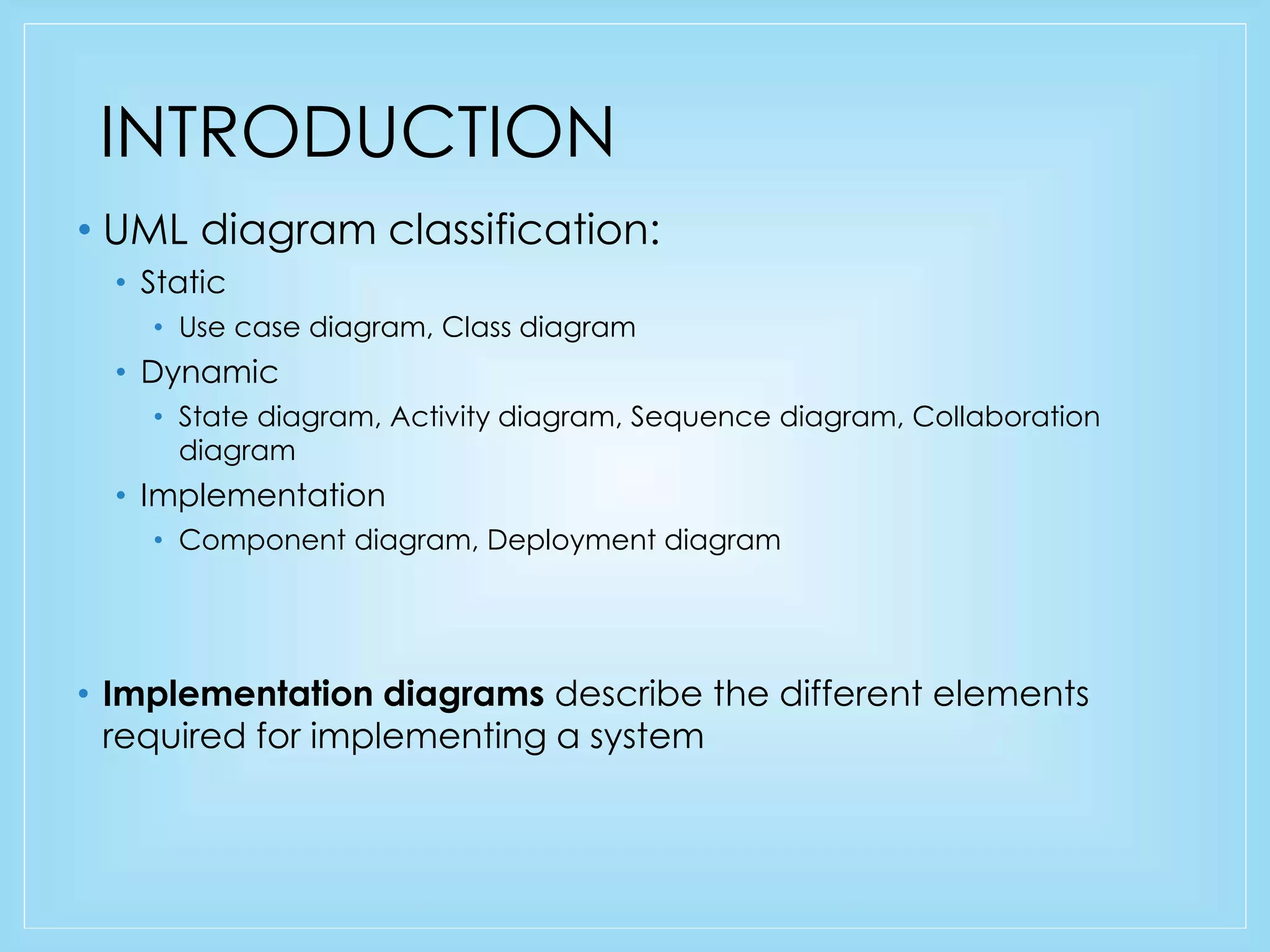


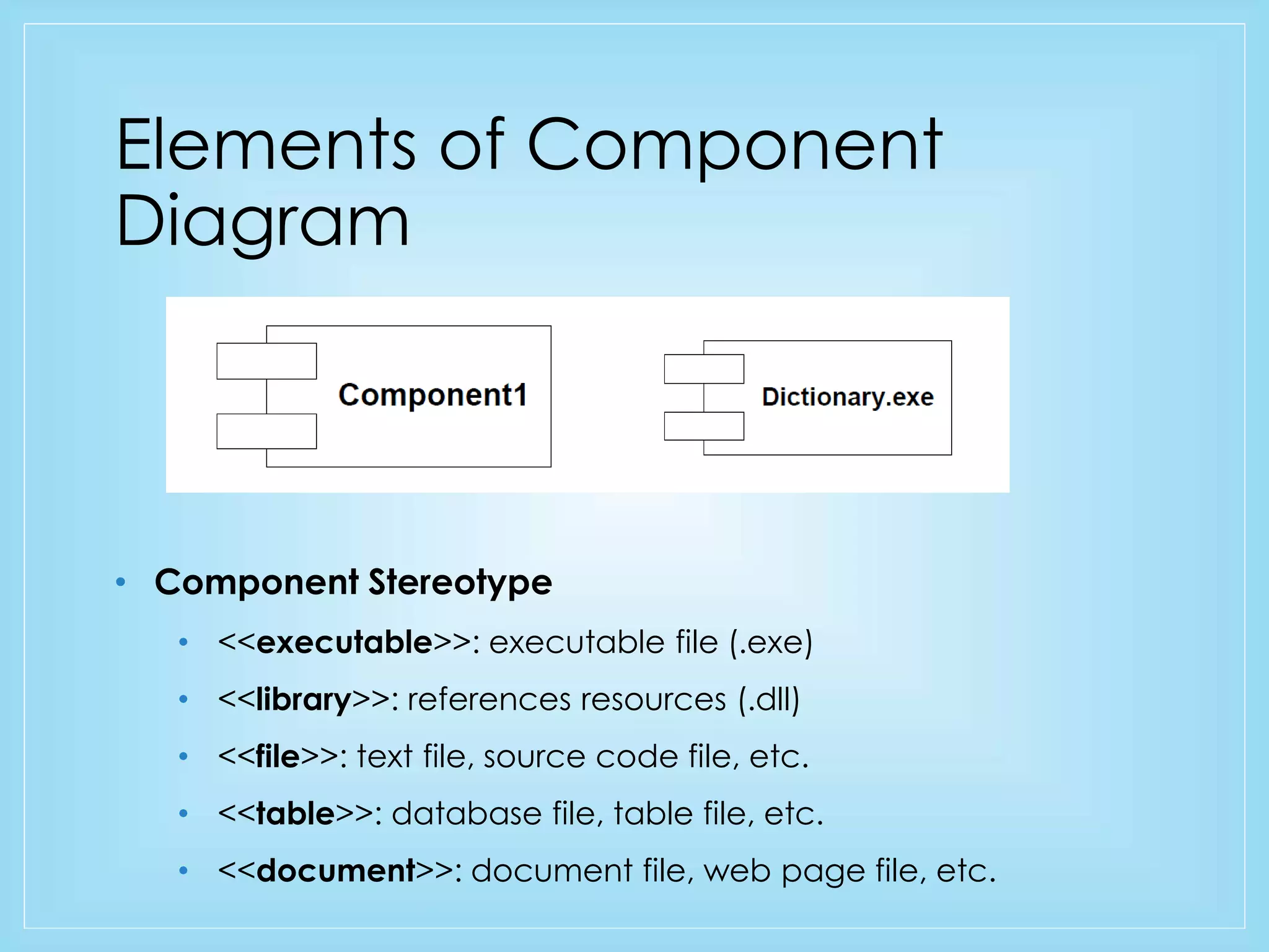

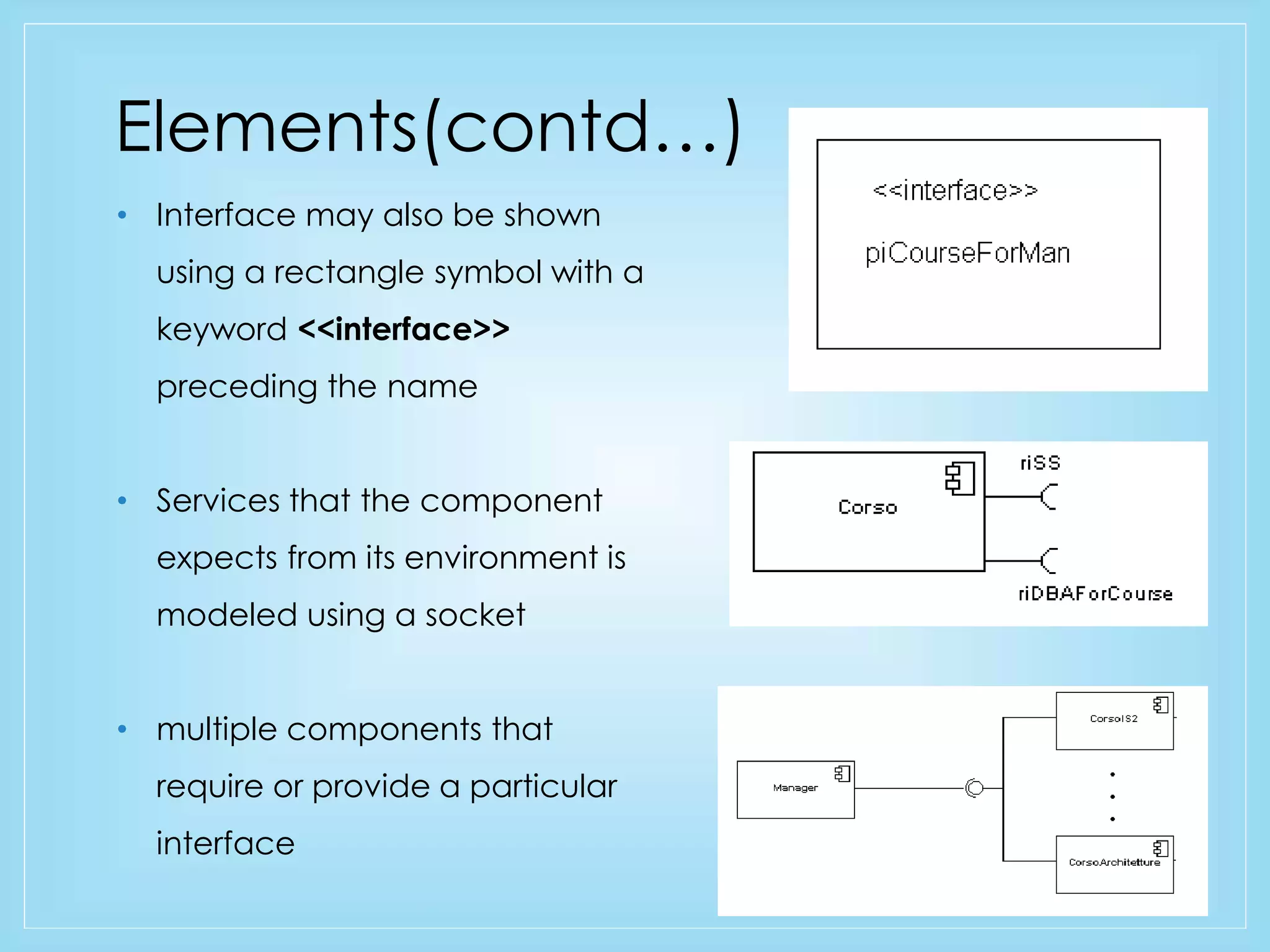

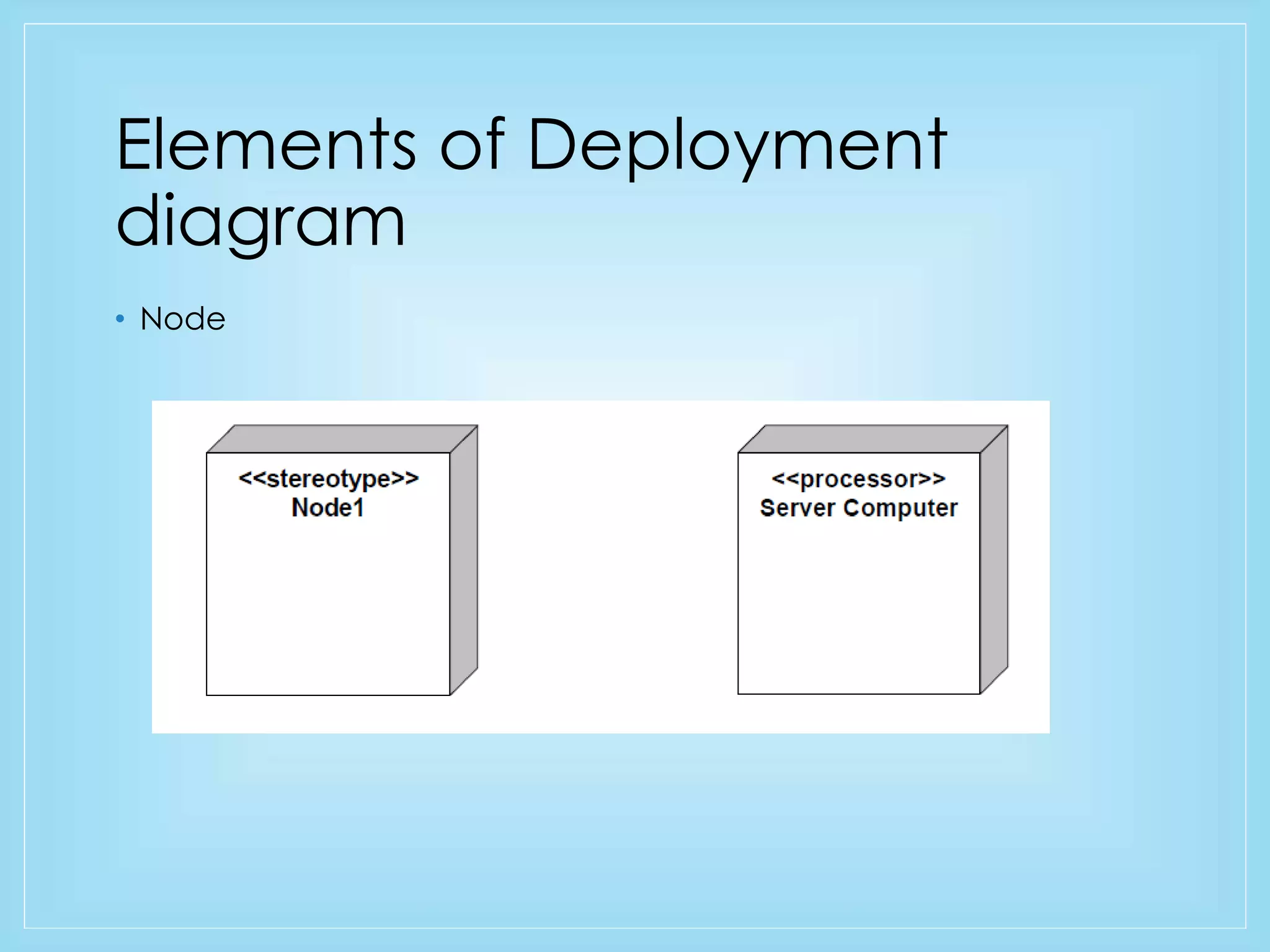

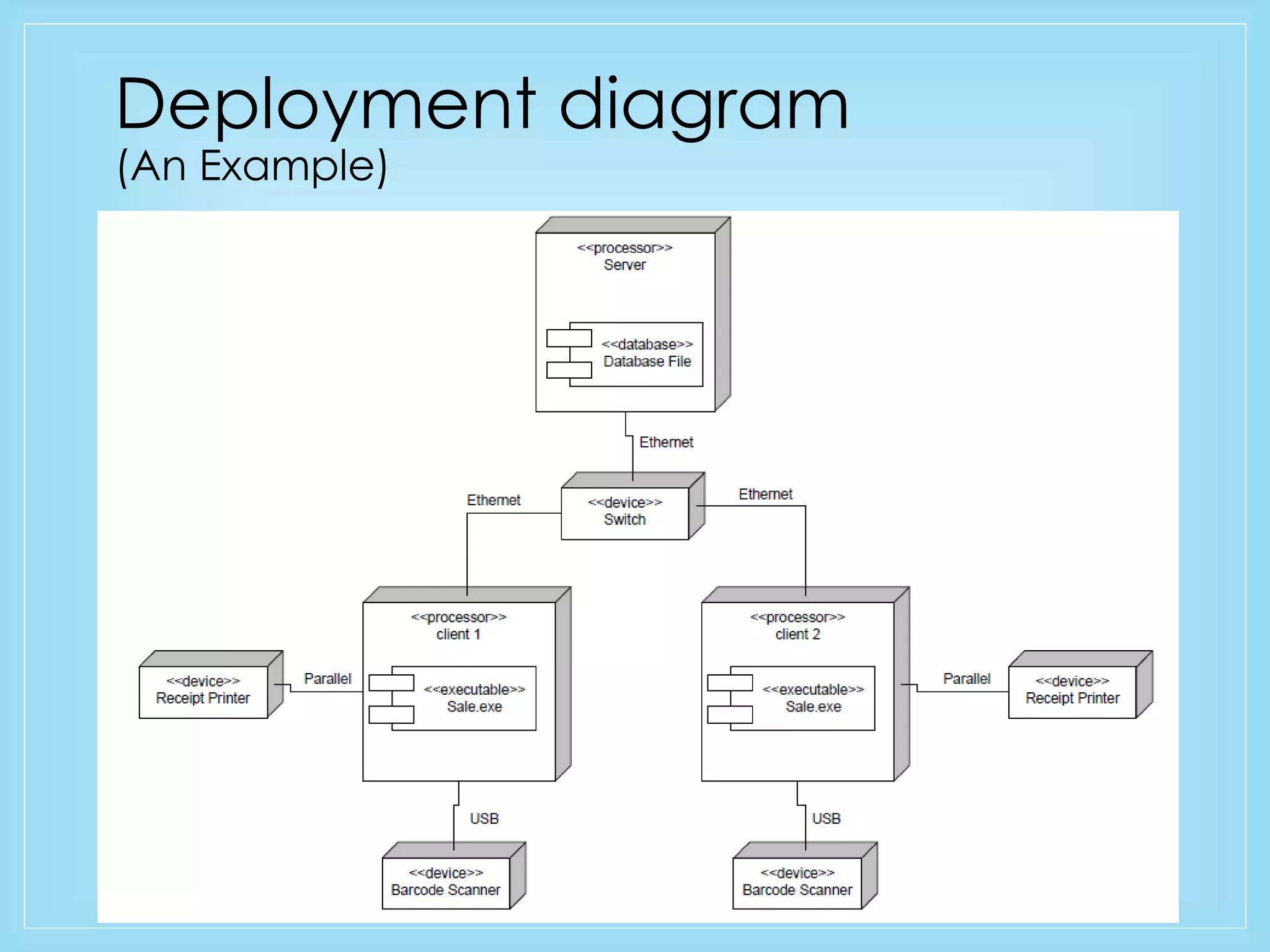
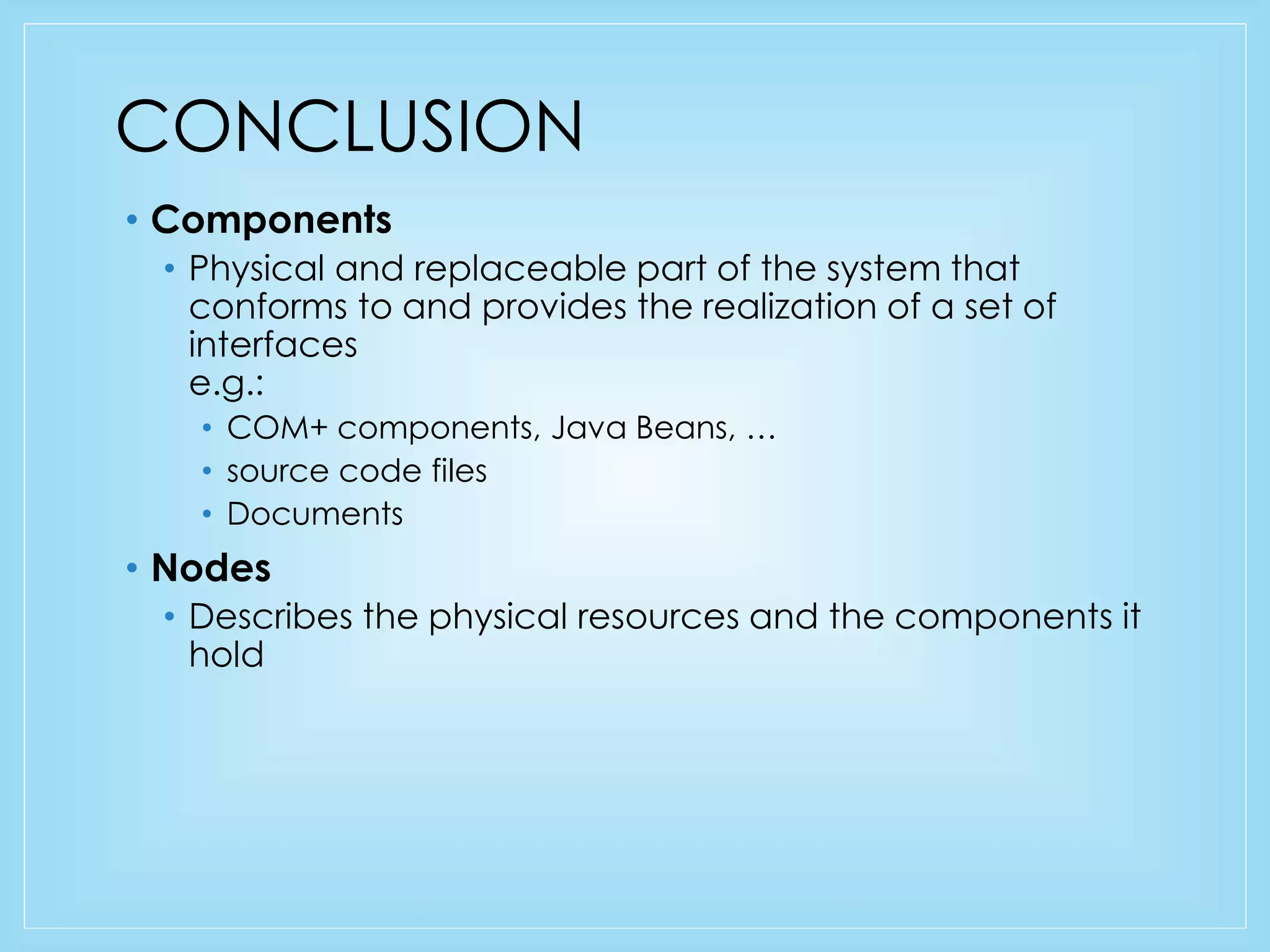


This document discusses component and deployment diagrams in UML. Component diagrams model the physical implementation of software by showing components, interfaces, and dependencies. They can include executable files, libraries, source code files, and data files. Deployment diagrams describe the physical hardware resources of a system, showing nodes like servers and PCs, and how software components are deployed on those nodes. Examples of both diagrams are also presented.