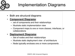
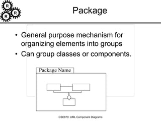
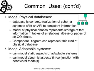
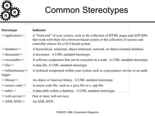
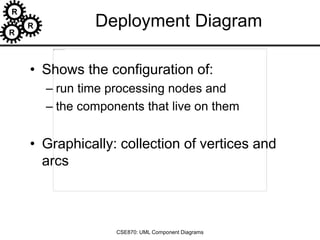
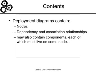
The document discusses UML component and deployment diagrams, which are structural diagrams illustrating the architecture of systems. Component diagrams represent components, their relationships, and dependencies, while deployment diagrams showcase the runtime configuration of nodes and their associated components. It also covers guidelines, common stereotypes, and modeling practices for both types of diagrams, emphasizing organization, naming conventions, and visual representation.

![R
R
R
CSE870: UML Component Diagrams
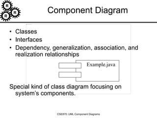
Interfaces
• Definition:
– Collection of operation signatures and/or attribute defns
– Defines a cohesive set of behaviors
• Realized by:
– Implemented by classes and components
– Implement operations/attributes defined by interface
• Relationships:
– A class can implement 0 or more interfaces
– An interface can be implemented by 1 or more classes
• Notation:
– Lollipop
– Dashed arrow
[Ambler, 2002-2005]](https://image.slidesharecdn.com/06-uml-component-220910212834-58c7fdb2/85/06-uml-component-ppt-5-320.jpg)
![R
R
R
CSE870: UML Component Diagrams
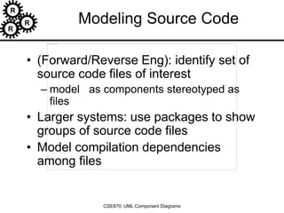
Sample interfaces
[Ambler, 2002-2005]](https://image.slidesharecdn.com/06-uml-component-220910212834-58c7fdb2/85/06-uml-component-ppt-6-320.jpg)
![R
R
R
CSE870: UML Component Diagrams
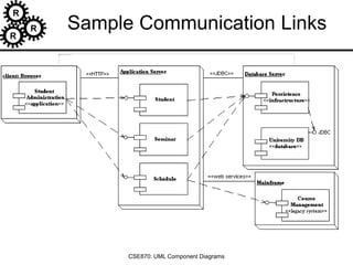
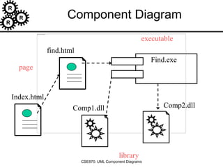
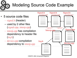
Example Component Diagram
[Ambler, 2002-2005]](https://image.slidesharecdn.com/06-uml-component-220910212834-58c7fdb2/85/06-uml-component-ppt-7-320.jpg)
![R
R
R
CSE870: UML Component Diagrams
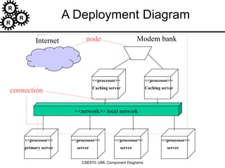
Guidelines for Deployment Diagrams
• General [Ambler 2002-2005]
– Indicate Software Components on Project-Specific
Diagrams
– Focus on Nodes and Communication Associations
on Enterprise-Level Diagrams
• Nodes and Components
– Name Nodes With Descriptive Terms
– Model Only Vital Software Components
– Apply Consistent Stereotypes to Components
– Apply Visual Stereotypes to Nodes
• Dependencies and Communication Associations
– Indicate Communication Protocols Via
Stereotypes
– Model Only Critical Dependencies Between
Components](https://image.slidesharecdn.com/06-uml-component-220910212834-58c7fdb2/85/06-uml-component-ppt-21-320.jpg)