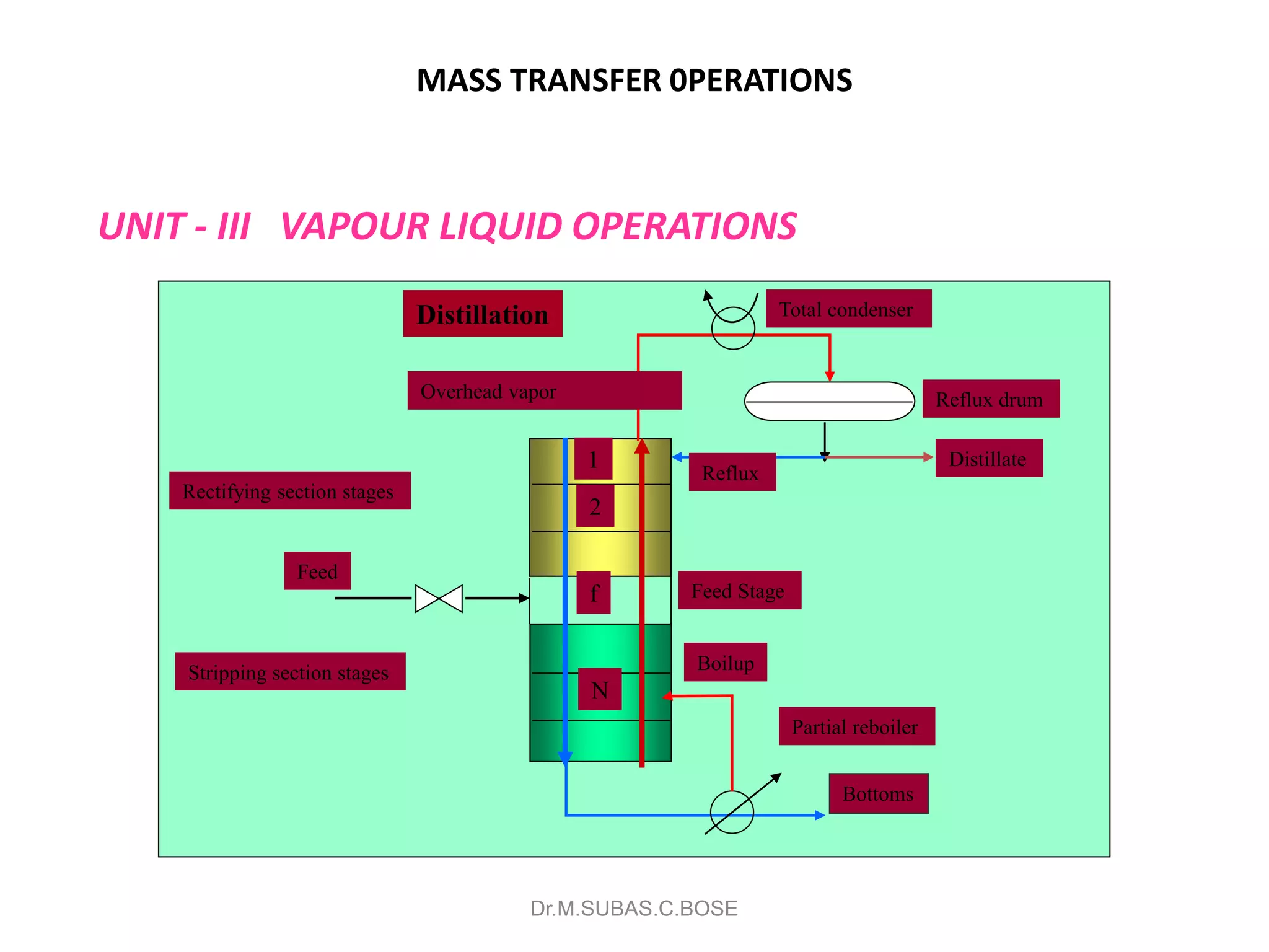
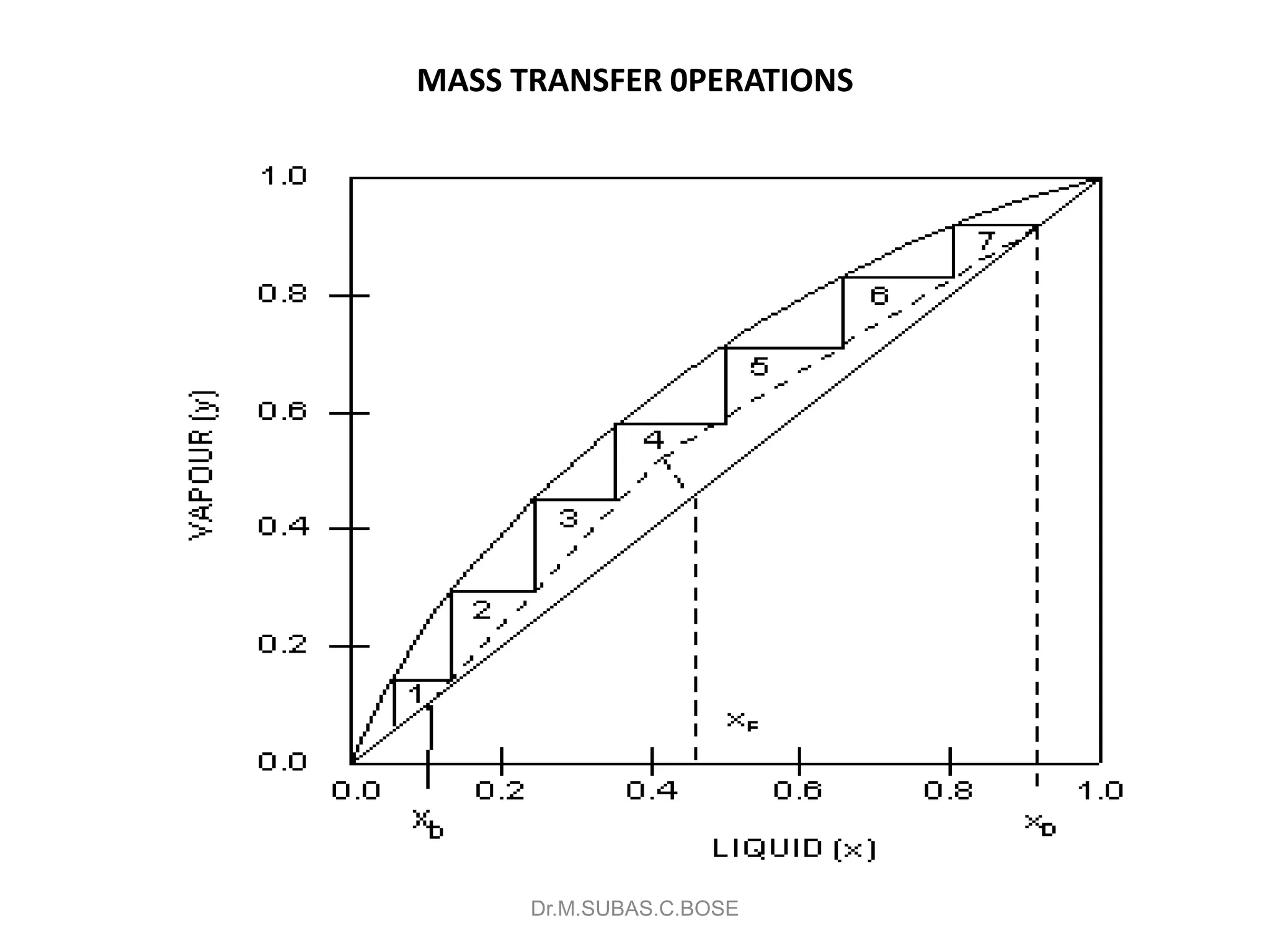
(V semester Sec A/B)
By
Dr.M.SUBAS CHANDRA BOSE(Assistant Prof)(BT34),
&
Mrs.SABARUNISHA BEGUM(Assistant Prof)(BT29)
Bio Technology, REC
Dr.M.SUBAS.C.BOSE
MASS TRANSFER 0PERATIONS
MASS TRANSFER
● Transfer of material from one homogeneous phase to
another. With or without phase change.
Dr.M.SUBAS.C.BOSE
MASS TRANSFER 0PERATIONS
UNIT - I DIFFUSION & MASS TRANSFER
Dr.M.SUBAS.C.BOSE
MASS TRANSFER 0PERATIONS
DIFFUSION
The term mass transfer Diffusion is used to denote the transference of a component in a
mixture
from a region where its concentration is high to a region where the concentration is lower.
Mass transfer process can take place in a gas or vapour or in a liquid, and it can result
from the random velocities of the molecules (molecular diffusion) or from the circulating
or eddy currents present in a turbulent fluid (eddy diffusion).
Dr.M.SUBAS.C.BOSE
MASS TRANSFER 0PERATIONS
A simple example of a mass transfer process is that occurring in a box consisting of
two compartments, each containing a different gas, initially separated by an impermeable
partition. When the partition is removed the gases start to mix and the mixing process
continues at a constantly decreasing rate until eventually (theoretically after the elapse of
an infinite time) the whole system acquires a uniform composition. The process is one
of molecular diffusion in which the mixing is attributable solely to the random motion
of the molecules. The rate of diffusion is governed by Pick's Law, first proposed by
FlCK(I) in 1855 which expresses the mass transfer rate as a linear function of the molar
concentration gradient. In a mixture of two gases A and B, assumed ideal, Pick's Law
for steady state diffusion may be written as:
Dr.M.SUBAS.C.BOSE
MASS TRANSFER 0PERATIONS
DIFFUSION IN BINARY GAS MIXTURES
10.2.1, Properties of binary mixtures
If A and B are ideal gases in a mixture, the ideal gas law, equation 2.15, may be applied
to each gas separately and to the mixture:
PAV = nART
PBV = nRRT
PV = nRT
where nA and HB are the number of moles of A and B and n is the total number of
moles in a volume V, and PA , PB and P are the respective partial pressures and the total
pressure.
Dr.M.SUBAS.C.BOSE
MASS TRANSFER 0PERATIONS
Equimolecular counterdiffusion
When the mass transfer rates of the two components are equal and opposite the process is
said to be one of equimolecular counterdiffusion. Such a process occurs in the case of the
box with a movable partition, referred to in Section 10.1. It occurs also in a distillation
column when the molar latent heats of the two components are the same. At any point
in the column a falling stream of liquid is brought into contact with a rising stream of
vapour with which it is not in equilibrium. The less volatile component is transferred from
the vapour to the liquid and the more volatile component is transferred in the opposite
direction. If the molar latent heats of the components are equal, the condensation of
a given amount of less volatile component releases exactly the amount of latent heat
required to volatilise the same molar quantity of the more volatile component. Thus at
the interface, and consequently throughout the liquid and vapour phases, equimolecular
counterdiffusion is taking place.
Dr.M.SUBAS.C.BOSE
MASS TRANSFER 0PERATIONS
Mass transfer through a stationary second component
In several important processes, one component in a gaseous mixture will be transported
relative to a fixed plane, such as a liquid interface, for example, and the other will undergo
no net movement. In gas absorption a soluble gas A is transferred to the liquid surface
where it dissolves, whereas the insoluble gas B undergoes no net movement with respect
to the interface. Similarly, in evaporation from a free surface, the vapour moves away
from the surface but the air has no net movement.
The concept of a stationary component may be envisaged by considering the effect of
moving the box, discussed in Section 10.1, in the opposite direction to that in which B is
diffusing, at a velocity equal to its diffusion velocity, so that to the external observer B
appears to be stationary. The total velocity at which A is transferred will then be increased
to its diffusion velocity plus the velocity of the box.
For the absorption of a soluble gas A from a mixture with an insoluble gas B, the
respective diffusion rates are given by:
NA = - D AB
Dr.M.SUBAS.C.BOSE
MASS TRANSFER 0PERATIONS
Mass transfer velocities
It is convenient to express mass transfer rates in terms of velocities for the species under
consideration where:
As a result of the diffusional process, there is no net overall molecular flux arising from
diffusion in a binary mixture, the two components being transferred at equal and opposite
rates. In the process of equimolecular counterdiffusion which occurs, for example, in a
distillation column when the two components have equal molar latent heats, the diffusional
velocities are the same as the velocities of the molecular species relative to the walls of
the equipment or the phase boundary.
Dr.M.SUBAS.C.BOSE
MASS TRANSFER 0PERATIONS
Thermal diffusion
If a temperature gradient is maintained in a binary gaseous mixture, a concentration
gradient is established with the light component collecting preferentially at the hot end
and the heavier one at the cold end. This phenomenon, known as the Soret effect, may be
used as the basis of a separation technique of commercial significance in the separation
of isotopes.
Conversely, when mass transfer is occurring as a result of a constant concentration
gradient, a temperature gradient may be generated; this is known as the Dufour effect.
In a binary mixture consisting of two gaseous components A and B subject to a temperature
gradient, the flux due to thermal diffusion is given by GREW and IBBS
Dr.M.SUBAS.C.BOSE
MASS TRANSFER 0PERATIONS
UNIT - II GAS LIQUID OPERATIONS
Dr.M.SUBAS.C.BOSE
MASS TRANSFER 0PERATIONS
Gas absorption principles
Liquid/Gas Absorption ops
includes absorption, stripping and desorption
soluble vapour absorbed from mixture with a liquid (solute), solute is
then regenerated  can also have gas absorption with reaction.
Dr.M.SUBAS.C.BOSE
MASS TRANSFER 0PERATIONS
The removal of one or more selected components from a mixture of gases
by absorption into a suitable liquid is the second major operation of
chemical engineering that is based on interphase mass transfer controlled
largely by rates of diffusion. Thus, acetone can be recovered from an
acetone–air mixture by passing the gas stream into water in which the
acetone dissolves while the air passes out. Similarly, ammonia may be
removed from an ammonia–air mixture by absorption in water. In each of
these examples the process of absorption of the gas in the liquid may be
treated as a physical process, the chemical reaction having no appreciable
effect
Dr.M.SUBAS.C.BOSE
MASS TRANSFER 0PERATIONS
The transfer unit
The group (dy/ye − y), which is used in Chapter 11, has been
defined by CHILTON and
COLBURN(52) as the number of overall gas transfer units NOG.
The concept of the transfer
unit is also introduced in Volume 1, Chapter 10. The application
of this group to the
countercurrent conditions in the absorption tower is now
considered.
Over a small height dZ, the partial pressure of the diffusing
component A will change
by an amount dPAG.
Dr.M.SUBAS.C.BOSE
MASS TRANSFER 0PERATIONS
UNIT - III VAPOUR LIQUID OPERATIONS
Dr.M.SUBAS.C.BOSE
Total condenser
Feed
Overhead vapor
Boilup
N
2
1
Distillation
f
Reflux drum
Rectifying section stages
Stripping section stages
Feed Stage
Bottoms
Partial reboiler
Reflux
Distillate
MASS TRANSFER 0PERATIONS
Distillation and V-L Equilibria
Types of Distillation
Action on an Ideal Plate
Mass Balance in a Distillation Column
Determination of Ideal Number of Plates – McCabe –
Thiele Analysis
Differential or batch distillation
Flash or equilibrium distillation
Continuous Rectification – Binary systems
Dr.M.SUBAS.C.BOSE
MASS TRANSFER 0PERATIONS
Differential distillation:
The simplest examples of batch distillation at a single stage.
Starting with a still pot, initially full, heated at a constant rate. In this
process the vapour formed on boiling the liquid is removed at once from
the system.
Since this vapour is richer in the more volatile component, with this result
the composition of the product progressively alters.
Thus, whilst the vapour formed over a short period is in equilibrium with
the liquid
At the end of the process the liquid, which has been vaporized, is removed
as the bottom product.
Dr.M.SUBAS.C.BOSE
MASS TRANSFER 0PERATIONS
Let S be the number of mols of material in the still and x be the mol fraction
of component A.
Suppose an amount dS, containing a mol fraction y of A, be vaporised.
Then a material balance on component A gives:
ydS = d (Sx)
= S dx + x Ds
The integral on then right-hand side can be solved graphically if the
equilibrium relationship between y and x is available.
Thus, if over the range concerned the equilibrium relationship is a straight
line of the form y= m x + c
Dr.M.SUBAS.C.BOSE
MASS TRANSFER 0PERATIONS
This process consists of only a single stage, a complete
separation is impossible unless the relatively volatility is
finite. Application is restricted to conditions where a
preliminary separation is to be followed by a more
rigorous distillation, where high purifies is not required, or
where the mixture is very easily separated
Dr.M.SUBAS.C.BOSE
MASS TRANSFER 0PERATIONS
Flash & continuous distillation
This method is frequently carried out as a continuous process.
Consist of vaporizing a definite fraction of liquid feed in such a way that the
vapour evolved is in equilibrium with the residual liquid.
The feed is usually pumped through a fired heater and enters the still through a
valve where the pressure is reduced.
The still is essentially a separator in which the liquid and vapour produced is
reduced by reduction in pressure with sufficient time to reach equilibrium. The
vapour is removed from the top of the separator and is then usually condensed,
while the liquid leaves from the bottom.
Dr.M.SUBAS.C.BOSE
MASS TRANSFER 0PERATIONS
Flash & continuous distillation
It is used in petroleum refining, in which petroleum fractions are heated in pipe stills
and the heated fluid flashed in to vapour and residual streams, each containing many
components.
Flash distillation is used most for separating components that boil at widely different
temperatures.
It is not effective separating components of comparable volatility, which requires the use
of distillation with reflux
By definition a vapour leaving a plate are brought into equilibrium.
Assume that the plates are numbered serially from top down and that the plate under
consideration is the nth plate from the bottom.
Then the immediately above plate n is plate n-1, and the immediately below is n+1.
Dr.M.SUBAS.C.BOSE
MASS TRANSFER 0PERATIONS
Material Balance diagram for plate n:
Dr.M.SUBAS.C.BOSE
Plate n
Vn,yn
Ln-1,Xn-1
Vn-1,yn-1
Ln-2,Xn-2
Plate n+1
Plate n -1
Vn+1,yn+1
Ln ,xn
MASS TRANSFER 0PERATIONS
For example if two fluid enter plate n and two leave it, the liquid, Ln-1 mol/h, from plate
n-1 and the stream of vapour, Vn+1 mol/h, from plate n+1 are brought into intimate
contact.
A stream of vapour, Vn mol/h, rises to plate n-1 and a stream of liquid, Ln mol/h,
descends to plate n+1.
Since the vapour streams are the V phase, their considerations are denoted by y; the
liquid streams are the L phase and their concentrations are denoted by x. Then the
concentrations of the streams entering and leaving the nth plate are as follows:
Vapour leaving plate, yn
Liquid leaving plate, xn
Vapour entering plate, yn+1
Liquid entering plate, xn-1
Dr.M.SUBAS.C.BOSE
MASS TRANSFER 0PERATIONS
Boiling-Point Diagram showing rectification on ideal plate:
Dr.M.SUBAS.C.BOSE
MASS TRANSFER 0PERATIONS
Number of Plates Required in a Distillation Column:
To develop a method for the design of distillation units to give the desired
fractionation, it is necessary to determine the numbers of trays.
Before that the heat and material flows over the trays, the condenser and
the reboiler must be established
Thermodynamic data is required to establish how much mass transfer is
needed to establish equilibrium between the stream leaving each tray.
The diameter of the column will be dictated by the necessity to
accommodate the desired flow rates, to operate within the available drop
in pressure, while at the same time affecting the desired degree of mixing
of the stream on each tray.
Dr.M.SUBAS.C.BOSE
MASS TRANSFER 0PERATIONS
Summary of the material balances for two components systems:
Let the process be analysed simply for a binary mixture of A and B as follows:
Let F be the number of mols per unit of feed of mol fraction xf of A.
D be the number of mols per unit time of vapour formed with y the mol fraction of A and
B be the number of mols per unit time of liquid with x the mol fraction of A. Then an
overall mass balance gives:
F = D + B
Component A balance
FxF = D xD + B xB
Dr.M.SUBAS.C.BOSE
MASS TRANSFER 0PERATIONS
Eliminating B and D from these equations give the follow:
Net flow rates. Quantity D is the difference between the flow rates of the streams
entering and leaving the top of the column. A material balance around the condenser
and accumulator in the gives:
Dr.M.SUBAS.C.BOSE
BD
FD
BD
BF
xx
xx
F
B
xx
xx
F
D






D V La a 
MASS TRANSFER 0PERATIONS
Eliminating B and D from these equations gives the following:
The difference between the flow rates of vapour and liquid anywhere in the upper
section of the column is also equal to D. This surface includes the condenser and all
plates above n+1. A total material balance around this control surface gives:
Similar material balances for A give the following equations:
Quantity D xD is the net flows rate of the component A upward in the upper section of
the column. It too is constant throughout this part of the equipment. In the lower
section of the column the net flow rates are also constant but, are in a downward
direction.
Dr.M.SUBAS.C.BOSE
D V Ln n 1
Dx V Y L x V y L xD a a a a n n n n    1 1
MASS TRANSFER 0PERATIONS
The net flow of total material equals B; that of the component A is BxB. The following
equations apply:
Operating lines:
There are two sections in the column; there are also two operating lines, one for the
rectifying section and other for the stripping section.
For the first section (rectifying section) the operation line is represented by:
Dr.M.SUBAS.C.BOSE
B L L L V
Bx L x V y L x V y
b b m m
B b b b b m m m m
   
   

 
1
1 1
11
1




n
aaaa
n
n
n
n
V
xLyV
x
V
L
y
DL
Dx
x
DL
L
y
n
D
n
n
n
n



1
MASS TRANSFER 0PERATIONS
Substituting for DxD in the equation above and eliminating Vn+1
For the section below the feed plate, a material balance over control surface II gives
Rearranging this equation and taking into account that the slope is the ratio of liquid
flow to the vapour flow, and also eliminating Vm+1
Dr.M.SUBAS.C.BOSE
Bmmmm BxxLyV  11
DL
Dx
x
DL
L
y
n
D
n
n
n
n



1
BL
Bx
x
BL
L
y
m
B
m
m
m
m



1
MASS TRANSFER 0PERATIONS
Feed Line:
The conditions of the vapour rate or the liquid rate may change depending of the thermal
condition of the feed.
It is related to the heat to vaporize one mole of feed divided by molar latent
heat (q)
Various type of feed conditions:
Cold feed, q>1
Feed at bubble point (saturated liquid), q=1
Feed partially vapour, 0<q<1
Feed at dew point (saturated vapour), q=0
Feed superheated vapour q<0
Dr.M.SUBAS.C.BOSE
MASS TRANSFER 0PERATIONS
Feed Line - Diagram:
Dr.M.SUBAS.C.BOSE
MASS TRANSFER 0PERATIONS
Feed Line:
Cold feed : It is assumed that the entire feed stream adds to the liquid flowing down the
column.
Feed at bubble point: no condensation is required to heat the feed.
Feed partial vapour: the liquid portion of the feed becomes part of the L and the vapour
portion becomes part of V
Feed saturated vapour the entire feed becomes part of the V
Feed superheated: part of the liquid from the rectifying column is vaporized to cool the
feed to a state of saturated vapour.
Feed Line Equation:
If xq = xF, and yq =xF then;
The point of intersection of the two operating lines lies on the straight line of slope
(q/q -1) and intercept (xF, yF)
Dr.M.SUBAS.C.BOSE
11 



q
x
x
q
q
y F
qq
MASS TRANSFER 0PERATIONS
Reflux Ratio:
The analysis of fractionating columns is facilitated by the use of a quantity called reflux
ratio.
Two ratios are used, one is the ratio of the reflux to the overhead product and the other
is the ratio of the reflux to the vapour.
Both ratios refer to quantities in the rectifying section. The equations for those ratios are
If the operation lines equations are divided D, the result is, for constant molar overflow,
This equation is an operation line of the rectifying section
Dr.M.SUBAS.C.BOSE
DL
L
V
L
Rand
D
DV
D
L
R VD




11
1




D
D
n
D
D
n
R
x
x
R
R
y
MASS TRANSFER 0PERATIONS
Reflux Ratio:
The y intercept of this line is xD/(RD+1).
The concentration xD is set by the conditions of the design.
RD, the reflux ratio, is an operating variable that can be controlled at will by adjusting the
split between reflux and overhead product or by changing the amount of vapour formed
in the reboiler for a given flow rate of the overhead product.
A point at the upper end of the operating line can be obtained by setting xn equal to xD in
the equation above.
A point at the upper end of the operating line can be obtained by setting xn equal to xD in
the previous equation.
The operating line for the rectifying section then intersects the diagonal at point (xD, xD).
Dr.M.SUBAS.C.BOSE
 
Dn
D
DD
D
D
D
D
D
n xyor
R
Rx
R
x
x
R
R
y 






  11
1
1
11
MASS TRANSFER 0PERATIONS
The operation lines represented by those two equations are plotted with the equilibrium
curve on the x-y diagram.Those equations also show that unless Ln and Lm are constant,
the operating lines are curved.The lines can be plotted only if the change in these
internal streams with concentration is known.
Dr.M.SUBAS.C.BOSE
a
e
b
xF
Minimum
Reflux
Total
(Maximum)
Reflux
MASS TRANSFER 0PERATIONS
Influence of the Number of Reflux Ratio:
Any change in R will therefore modify the slope of the operation line as can be seen from
the Figure
Dr.M.SUBAS.C.BOSE
a
e
b
xF
Minimum
Reflux
MASS TRANSFER 0PERATIONS
If no product is withdrawn from the still (D=0), the column is said to operate under
conditions of total reflux and, as seen from equation , the top operating line has its
maximum slope of unity, and coincides with the line x=y.
The step become very close to the plate above, these conditions are known as minimum
reflux and Rm denotes the reflux ratio.
Any small increase in R beyond Rm will give a workable system, though a large numbers
of plate will be required.
The minimum number of plates is required for a given separation at conditions of total
reflux
There is a minimum reflux ratio below which it is impossible to obtain the desired
enrichment, however many plates are used.
Dr.M.SUBAS.C.BOSE
a
e
b
xF
Minimum
Reflux
MASS TRANSFER 0PERATIONS
Calculation of Minimum Reflux Ratio Rm
Based on the previous figure, the slope of the line ad is given by
Dr.M.SUBAS.C.BOSE
a
e
b
xF
Minimum
Reflux
1
m D F D F
m
m D F F F
R x x x y
or R
R x x y x
 

  
MASS TRANSFER 0PERATIONS
McCabe -Thiele principles
Construction the operation lines:
Locate the feed line Calculate the y-axis intercept xD/(RD + 1) of
the rectifying line and plot that line through the intercept and
the point (xD, xD)
Draw the stripping line through point (xB,xB) and the
intersection of the rectifying line with the feed line.
Dr.M.SUBAS.C.BOSE
MASS TRANSFER 0PERATIONS
Effect the feed condition on feed line:
If the feed is a cold liquid, the feed line slopes will be
upward and to the right;
if the feed is a saturated liquid, the line is vertical;
if the feed is a mixture of liquid and vapour, the lines
slopes upward and to the left and the slope is the negative of
the ratio of the liquid to the vapour;
if the feed is saturated vapour the line is horizontal and
if the feed is superheated vapour. The lines slope
downward and to the left.
Dr.M.SUBAS.C.BOSE
MASS TRANSFER 0PERATIONS
Feed Plate location
After the location of the feed plate the construction of the
number of ideal trays is found by the usual step-by step
construction. The process can begin at the top and also a total
condenser is used.
Dr.M.SUBAS.C.BOSE
MASS TRANSFER 0PERATIONS
Dr.M.SUBAS.C.BOSE
MASS TRANSFER 0PERATIONS
UNIT - IV EXTRACTION OPERATIONS
Dr.M.SUBAS.C.BOSE
MASS TRANSFER 0PERATIONS
Liquid–Liquid Extraction
13.1. INTRODUCTION
The separation of the components of a liquid mixture by treatment with a solvent in
which one or more of the desired components is preferentially soluble is known as
liquid–liquid extraction—an operation which is used, for example, in the processing
of coal tar liquids and in the production of fuels in the nuclear industry, and which
has been applied extensively to the separation of hydrocarbons in the petroleum
industry. In this operation, it is essential that the liquid-mixture feed and solvent are
at least partially if not completely immiscible and, in essence, three stages are
involved:
(a) Bringing the feed mixture and the solvent into intimate contact,
(b) Separation of the resulting two phases, and
(c) Removal and recovery of the solvent from each phase.
Dr.M.SUBAS.C.BOSE
MASS TRANSFER 0PERATIONS
Stage wise Extraction
Dr.M.SUBAS.C.BOSE
MASS TRANSFER 0PERATIONS
Continuous Extraction
Dr.M.SUBAS.C.BOSE
MASS TRANSFER 0PERATIONS
Dr.M.SUBAS.C.BOSE
MASS TRANSFER 0PERATIONS
General principles of Leaching
Leaching is concerned with the extraction of a soluble constituent from a
solid by means
of a solvent. The process may be used either for the production of a
concentrated solution
of a valuable solid material, or in order to remove an insoluble solid, such
as a pigment,
from a soluble material with which it is contaminated. The method used for
the extraction
is determined by the proportion of soluble constituent present, its
distribution throughout
the solid, the nature of the solid and the particle size.
Dr.M.SUBAS.C.BOSE
MASS TRANSFER 0PERATIONS
Factors influencing the rate of extraction
The selection of the equipment for an extraction process is influenced by
the factors which
are responsible for limiting the extraction rate. Thus, if the diffusion of the
solute through
the porous structure of the residual solids is the controlling factor, the
material should be
of small size so that the distance the solute has to travel is small. On the
other hand, if
diffusion of the solute from the surface of the particles to the bulk of the
solution is the
controlling factor, a high degree of agitation of the fluid is required.
Dr.M.SUBAS.C.BOSE
MASS TRANSFER 0PERATIONS
EQUIPMENT FOR LEACHING
Processes involved
Three distinct processes are usually involved in leaching operations:
(a) Dissolving the soluble constituent.
(b) Separating the solution, so formed, from the insoluble solid residue.
(c) Washing the solid residue in order to free it of unwanted soluble matter or to obtain
as much of the soluble material as possible as the product.
Leaching has in the past been carried out mainly as a batch process although many
continuous plants have also been developed. The type of equipment employed depends on
the nature of the solid—whether it is granular or cellular and whether it is coarse or fine.
The normal distinction between coarse and fine solids is that the former have sufficiently
large settling velocities for them to be readily separable from the liquid, whereas the
latter can be maintained in suspension with the aid of only a small amount of agitation.
Dr.M.SUBAS.C.BOSE
MASS TRANSFER 0PERATIONS
UNIT - V SOLID FLUID OPERATIONS
Dr.M.SUBAS.C.BOSE
MASS TRANSFER 0PERATIONS
INTRODUCTION - ADSORPTION
Although adsorption has been used as a physical-chemical process for many years, it is
only over the last four decades that the process has developed to a stage where it is now
a major industrial separation technique. In adsorption, molecules distribute themselves
between two phases, one of which is a solid whilst the other may be a liquid or a gas.
The only exception is in adsorption on to foams, a topic which is not considered in this
chapter.
Unlike absorption, in which solute molecules diffuse from the bulk of a gas phase to
the bulk of a liquid phase, in adsorption, molecules diffuse from the bulk of the fluid to
the surface of the solid adsorbent forming a distinct adsorbed phase.
Dr.M.SUBAS.C.BOSE
MASS TRANSFER 0PERATIONS
The adsorption which results from the influence of van der Waals forces is
essentially
physical in nature. Because the forces are not strong, the adsorption may be easily
reversed.
In some systems, additional forces bind absorbed molecules to the solid surface.
These are chemical in nature involving the exchange or sharing of electrons, or
possibly molecules
forming atoms or radicals. In such cases the term chemisorption is used to describe
the phenomenon. This is less easily reversed than physical adsorption, and
regeneration may be a problem. Chemisorption is restricted to just one layer of
molecules on the surface, although it may be followed by additional layers of
physically adsorbed molecules.
Dr.M.SUBAS.C.BOSE
MASS TRANSFER 0PERATIONS
MOISTURE CONTENT RELATIONSHIPS:
MOISTURE/SOLID EQUILIBRIUM RELATIONSHIPS DEFINED ON THE BASIS OF
RELATIVE HUMIDITY AT A SPECIFIC TEMPERATURE EQUILIBRIUM AMOUNT
OF MOISTURE TENDS TO DECREASE WITH INCREASING TEMPERATURE.
Dr.M.SUBAS.C.BOSE
MASS TRANSFER 0PERATIONS
MOISTURE CONTENT VARIABLES BASED ON THE MASS OF MOISTURE
RELATIVE TO THE MASS BONE DRY SOLID
Dr.M.SUBAS.C.BOSE
MASS TRANSFER 0PERATIONS
DRYING RATE CURVES:
DEPEND ON WHETHER HEAT ORMASS TRANSFER CONTROLS FREE MOISTURE VS.
TIME DRYING RATE VS. MOISTURE CONTENT
Dr.M.SUBAS.C.BOSE
MASS TRANSFER 0PERATIONS
DRYING REGIMES CONSTANT RATE - NO LIMIT TO MASS TRANSFER IN SOLID PHASE
SURFACE MOISTURE TRANSFER NEAR SURFACE FALLING RATE – MOISTURE FLUX
THROUGH THE SOLID IS HINDERED CRITICAL POINTS OCCUR BETWEEN CONSTANT
RATE AND FALLING RATE WITH A CHANGE IN THE FALLING RATE DRYING
MECHANISM.
Dr.M.SUBAS.C.BOSE
MASS TRANSFER 0PERATIONS
FALLING RATE EXAMPLE:
Dr.M.SUBAS.C.BOSE
MASS TRANSFER 0PERATIONS
FALLING RATE EXAMPLE:
Dr.M.SUBAS.C.BOSE
MASS TRANSFER 0PERATIONS
Dr.M.SUBAS.C.BOSE

Iso 8859-1 -mass transfer operations

  • 1.
    (V semester SecA/B) By Dr.M.SUBAS CHANDRA BOSE(Assistant Prof)(BT34), & Mrs.SABARUNISHA BEGUM(Assistant Prof)(BT29) Bio Technology, REC Dr.M.SUBAS.C.BOSE
  • 2.
    MASS TRANSFER 0PERATIONS MASSTRANSFER ● Transfer of material from one homogeneous phase to another. With or without phase change. Dr.M.SUBAS.C.BOSE
  • 3.
    MASS TRANSFER 0PERATIONS UNIT- I DIFFUSION & MASS TRANSFER Dr.M.SUBAS.C.BOSE
  • 4.
    MASS TRANSFER 0PERATIONS DIFFUSION Theterm mass transfer Diffusion is used to denote the transference of a component in a mixture from a region where its concentration is high to a region where the concentration is lower. Mass transfer process can take place in a gas or vapour or in a liquid, and it can result from the random velocities of the molecules (molecular diffusion) or from the circulating or eddy currents present in a turbulent fluid (eddy diffusion). Dr.M.SUBAS.C.BOSE
  • 5.
    MASS TRANSFER 0PERATIONS Asimple example of a mass transfer process is that occurring in a box consisting of two compartments, each containing a different gas, initially separated by an impermeable partition. When the partition is removed the gases start to mix and the mixing process continues at a constantly decreasing rate until eventually (theoretically after the elapse of an infinite time) the whole system acquires a uniform composition. The process is one of molecular diffusion in which the mixing is attributable solely to the random motion of the molecules. The rate of diffusion is governed by Pick's Law, first proposed by FlCK(I) in 1855 which expresses the mass transfer rate as a linear function of the molar concentration gradient. In a mixture of two gases A and B, assumed ideal, Pick's Law for steady state diffusion may be written as: Dr.M.SUBAS.C.BOSE
  • 6.
    MASS TRANSFER 0PERATIONS DIFFUSIONIN BINARY GAS MIXTURES 10.2.1, Properties of binary mixtures If A and B are ideal gases in a mixture, the ideal gas law, equation 2.15, may be applied to each gas separately and to the mixture: PAV = nART PBV = nRRT PV = nRT where nA and HB are the number of moles of A and B and n is the total number of moles in a volume V, and PA , PB and P are the respective partial pressures and the total pressure. Dr.M.SUBAS.C.BOSE
  • 7.
    MASS TRANSFER 0PERATIONS Equimolecularcounterdiffusion When the mass transfer rates of the two components are equal and opposite the process is said to be one of equimolecular counterdiffusion. Such a process occurs in the case of the box with a movable partition, referred to in Section 10.1. It occurs also in a distillation column when the molar latent heats of the two components are the same. At any point in the column a falling stream of liquid is brought into contact with a rising stream of vapour with which it is not in equilibrium. The less volatile component is transferred from the vapour to the liquid and the more volatile component is transferred in the opposite direction. If the molar latent heats of the components are equal, the condensation of a given amount of less volatile component releases exactly the amount of latent heat required to volatilise the same molar quantity of the more volatile component. Thus at the interface, and consequently throughout the liquid and vapour phases, equimolecular counterdiffusion is taking place. Dr.M.SUBAS.C.BOSE
  • 8.
    MASS TRANSFER 0PERATIONS Masstransfer through a stationary second component In several important processes, one component in a gaseous mixture will be transported relative to a fixed plane, such as a liquid interface, for example, and the other will undergo no net movement. In gas absorption a soluble gas A is transferred to the liquid surface where it dissolves, whereas the insoluble gas B undergoes no net movement with respect to the interface. Similarly, in evaporation from a free surface, the vapour moves away from the surface but the air has no net movement. The concept of a stationary component may be envisaged by considering the effect of moving the box, discussed in Section 10.1, in the opposite direction to that in which B is diffusing, at a velocity equal to its diffusion velocity, so that to the external observer B appears to be stationary. The total velocity at which A is transferred will then be increased to its diffusion velocity plus the velocity of the box. For the absorption of a soluble gas A from a mixture with an insoluble gas B, the respective diffusion rates are given by: NA = - D AB Dr.M.SUBAS.C.BOSE
  • 9.
    MASS TRANSFER 0PERATIONS Masstransfer velocities It is convenient to express mass transfer rates in terms of velocities for the species under consideration where: As a result of the diffusional process, there is no net overall molecular flux arising from diffusion in a binary mixture, the two components being transferred at equal and opposite rates. In the process of equimolecular counterdiffusion which occurs, for example, in a distillation column when the two components have equal molar latent heats, the diffusional velocities are the same as the velocities of the molecular species relative to the walls of the equipment or the phase boundary. Dr.M.SUBAS.C.BOSE
  • 10.
    MASS TRANSFER 0PERATIONS Thermaldiffusion If a temperature gradient is maintained in a binary gaseous mixture, a concentration gradient is established with the light component collecting preferentially at the hot end and the heavier one at the cold end. This phenomenon, known as the Soret effect, may be used as the basis of a separation technique of commercial significance in the separation of isotopes. Conversely, when mass transfer is occurring as a result of a constant concentration gradient, a temperature gradient may be generated; this is known as the Dufour effect. In a binary mixture consisting of two gaseous components A and B subject to a temperature gradient, the flux due to thermal diffusion is given by GREW and IBBS Dr.M.SUBAS.C.BOSE
  • 11.
    MASS TRANSFER 0PERATIONS UNIT- II GAS LIQUID OPERATIONS Dr.M.SUBAS.C.BOSE
  • 12.
    MASS TRANSFER 0PERATIONS Gasabsorption principles Liquid/Gas Absorption ops includes absorption, stripping and desorption soluble vapour absorbed from mixture with a liquid (solute), solute is then regenerated  can also have gas absorption with reaction. Dr.M.SUBAS.C.BOSE
  • 13.
    MASS TRANSFER 0PERATIONS Theremoval of one or more selected components from a mixture of gases by absorption into a suitable liquid is the second major operation of chemical engineering that is based on interphase mass transfer controlled largely by rates of diffusion. Thus, acetone can be recovered from an acetone–air mixture by passing the gas stream into water in which the acetone dissolves while the air passes out. Similarly, ammonia may be removed from an ammonia–air mixture by absorption in water. In each of these examples the process of absorption of the gas in the liquid may be treated as a physical process, the chemical reaction having no appreciable effect Dr.M.SUBAS.C.BOSE
  • 14.
    MASS TRANSFER 0PERATIONS Thetransfer unit The group (dy/ye − y), which is used in Chapter 11, has been defined by CHILTON and COLBURN(52) as the number of overall gas transfer units NOG. The concept of the transfer unit is also introduced in Volume 1, Chapter 10. The application of this group to the countercurrent conditions in the absorption tower is now considered. Over a small height dZ, the partial pressure of the diffusing component A will change by an amount dPAG. Dr.M.SUBAS.C.BOSE
  • 15.
    MASS TRANSFER 0PERATIONS UNIT- III VAPOUR LIQUID OPERATIONS Dr.M.SUBAS.C.BOSE Total condenser Feed Overhead vapor Boilup N 2 1 Distillation f Reflux drum Rectifying section stages Stripping section stages Feed Stage Bottoms Partial reboiler Reflux Distillate
  • 16.
    MASS TRANSFER 0PERATIONS Distillationand V-L Equilibria Types of Distillation Action on an Ideal Plate Mass Balance in a Distillation Column Determination of Ideal Number of Plates – McCabe – Thiele Analysis Differential or batch distillation Flash or equilibrium distillation Continuous Rectification – Binary systems Dr.M.SUBAS.C.BOSE
  • 17.
    MASS TRANSFER 0PERATIONS Differentialdistillation: The simplest examples of batch distillation at a single stage. Starting with a still pot, initially full, heated at a constant rate. In this process the vapour formed on boiling the liquid is removed at once from the system. Since this vapour is richer in the more volatile component, with this result the composition of the product progressively alters. Thus, whilst the vapour formed over a short period is in equilibrium with the liquid At the end of the process the liquid, which has been vaporized, is removed as the bottom product. Dr.M.SUBAS.C.BOSE
  • 18.
    MASS TRANSFER 0PERATIONS LetS be the number of mols of material in the still and x be the mol fraction of component A. Suppose an amount dS, containing a mol fraction y of A, be vaporised. Then a material balance on component A gives: ydS = d (Sx) = S dx + x Ds The integral on then right-hand side can be solved graphically if the equilibrium relationship between y and x is available. Thus, if over the range concerned the equilibrium relationship is a straight line of the form y= m x + c Dr.M.SUBAS.C.BOSE
  • 19.
    MASS TRANSFER 0PERATIONS Thisprocess consists of only a single stage, a complete separation is impossible unless the relatively volatility is finite. Application is restricted to conditions where a preliminary separation is to be followed by a more rigorous distillation, where high purifies is not required, or where the mixture is very easily separated Dr.M.SUBAS.C.BOSE
  • 20.
    MASS TRANSFER 0PERATIONS Flash& continuous distillation This method is frequently carried out as a continuous process. Consist of vaporizing a definite fraction of liquid feed in such a way that the vapour evolved is in equilibrium with the residual liquid. The feed is usually pumped through a fired heater and enters the still through a valve where the pressure is reduced. The still is essentially a separator in which the liquid and vapour produced is reduced by reduction in pressure with sufficient time to reach equilibrium. The vapour is removed from the top of the separator and is then usually condensed, while the liquid leaves from the bottom. Dr.M.SUBAS.C.BOSE
  • 21.
    MASS TRANSFER 0PERATIONS Flash& continuous distillation It is used in petroleum refining, in which petroleum fractions are heated in pipe stills and the heated fluid flashed in to vapour and residual streams, each containing many components. Flash distillation is used most for separating components that boil at widely different temperatures. It is not effective separating components of comparable volatility, which requires the use of distillation with reflux By definition a vapour leaving a plate are brought into equilibrium. Assume that the plates are numbered serially from top down and that the plate under consideration is the nth plate from the bottom. Then the immediately above plate n is plate n-1, and the immediately below is n+1. Dr.M.SUBAS.C.BOSE
  • 22.
    MASS TRANSFER 0PERATIONS MaterialBalance diagram for plate n: Dr.M.SUBAS.C.BOSE Plate n Vn,yn Ln-1,Xn-1 Vn-1,yn-1 Ln-2,Xn-2 Plate n+1 Plate n -1 Vn+1,yn+1 Ln ,xn
  • 23.
    MASS TRANSFER 0PERATIONS Forexample if two fluid enter plate n and two leave it, the liquid, Ln-1 mol/h, from plate n-1 and the stream of vapour, Vn+1 mol/h, from plate n+1 are brought into intimate contact. A stream of vapour, Vn mol/h, rises to plate n-1 and a stream of liquid, Ln mol/h, descends to plate n+1. Since the vapour streams are the V phase, their considerations are denoted by y; the liquid streams are the L phase and their concentrations are denoted by x. Then the concentrations of the streams entering and leaving the nth plate are as follows: Vapour leaving plate, yn Liquid leaving plate, xn Vapour entering plate, yn+1 Liquid entering plate, xn-1 Dr.M.SUBAS.C.BOSE
  • 24.
    MASS TRANSFER 0PERATIONS Boiling-PointDiagram showing rectification on ideal plate: Dr.M.SUBAS.C.BOSE
  • 25.
    MASS TRANSFER 0PERATIONS Numberof Plates Required in a Distillation Column: To develop a method for the design of distillation units to give the desired fractionation, it is necessary to determine the numbers of trays. Before that the heat and material flows over the trays, the condenser and the reboiler must be established Thermodynamic data is required to establish how much mass transfer is needed to establish equilibrium between the stream leaving each tray. The diameter of the column will be dictated by the necessity to accommodate the desired flow rates, to operate within the available drop in pressure, while at the same time affecting the desired degree of mixing of the stream on each tray. Dr.M.SUBAS.C.BOSE
  • 26.
    MASS TRANSFER 0PERATIONS Summaryof the material balances for two components systems: Let the process be analysed simply for a binary mixture of A and B as follows: Let F be the number of mols per unit of feed of mol fraction xf of A. D be the number of mols per unit time of vapour formed with y the mol fraction of A and B be the number of mols per unit time of liquid with x the mol fraction of A. Then an overall mass balance gives: F = D + B Component A balance FxF = D xD + B xB Dr.M.SUBAS.C.BOSE
  • 27.
    MASS TRANSFER 0PERATIONS EliminatingB and D from these equations give the follow: Net flow rates. Quantity D is the difference between the flow rates of the streams entering and leaving the top of the column. A material balance around the condenser and accumulator in the gives: Dr.M.SUBAS.C.BOSE BD FD BD BF xx xx F B xx xx F D       D V La a 
  • 28.
    MASS TRANSFER 0PERATIONS EliminatingB and D from these equations gives the following: The difference between the flow rates of vapour and liquid anywhere in the upper section of the column is also equal to D. This surface includes the condenser and all plates above n+1. A total material balance around this control surface gives: Similar material balances for A give the following equations: Quantity D xD is the net flows rate of the component A upward in the upper section of the column. It too is constant throughout this part of the equipment. In the lower section of the column the net flow rates are also constant but, are in a downward direction. Dr.M.SUBAS.C.BOSE D V Ln n 1 Dx V Y L x V y L xD a a a a n n n n    1 1
  • 29.
    MASS TRANSFER 0PERATIONS Thenet flow of total material equals B; that of the component A is BxB. The following equations apply: Operating lines: There are two sections in the column; there are also two operating lines, one for the rectifying section and other for the stripping section. For the first section (rectifying section) the operation line is represented by: Dr.M.SUBAS.C.BOSE B L L L V Bx L x V y L x V y b b m m B b b b b m m m m            1 1 1 11 1     n aaaa n n n n V xLyV x V L y DL Dx x DL L y n D n n n n    1
  • 30.
    MASS TRANSFER 0PERATIONS Substitutingfor DxD in the equation above and eliminating Vn+1 For the section below the feed plate, a material balance over control surface II gives Rearranging this equation and taking into account that the slope is the ratio of liquid flow to the vapour flow, and also eliminating Vm+1 Dr.M.SUBAS.C.BOSE Bmmmm BxxLyV  11 DL Dx x DL L y n D n n n n    1 BL Bx x BL L y m B m m m m    1
  • 31.
    MASS TRANSFER 0PERATIONS FeedLine: The conditions of the vapour rate or the liquid rate may change depending of the thermal condition of the feed. It is related to the heat to vaporize one mole of feed divided by molar latent heat (q) Various type of feed conditions: Cold feed, q>1 Feed at bubble point (saturated liquid), q=1 Feed partially vapour, 0<q<1 Feed at dew point (saturated vapour), q=0 Feed superheated vapour q<0 Dr.M.SUBAS.C.BOSE
  • 32.
    MASS TRANSFER 0PERATIONS FeedLine - Diagram: Dr.M.SUBAS.C.BOSE
  • 33.
    MASS TRANSFER 0PERATIONS FeedLine: Cold feed : It is assumed that the entire feed stream adds to the liquid flowing down the column. Feed at bubble point: no condensation is required to heat the feed. Feed partial vapour: the liquid portion of the feed becomes part of the L and the vapour portion becomes part of V Feed saturated vapour the entire feed becomes part of the V Feed superheated: part of the liquid from the rectifying column is vaporized to cool the feed to a state of saturated vapour. Feed Line Equation: If xq = xF, and yq =xF then; The point of intersection of the two operating lines lies on the straight line of slope (q/q -1) and intercept (xF, yF) Dr.M.SUBAS.C.BOSE 11     q x x q q y F qq
  • 34.
    MASS TRANSFER 0PERATIONS RefluxRatio: The analysis of fractionating columns is facilitated by the use of a quantity called reflux ratio. Two ratios are used, one is the ratio of the reflux to the overhead product and the other is the ratio of the reflux to the vapour. Both ratios refer to quantities in the rectifying section. The equations for those ratios are If the operation lines equations are divided D, the result is, for constant molar overflow, This equation is an operation line of the rectifying section Dr.M.SUBAS.C.BOSE DL L V L Rand D DV D L R VD     11 1     D D n D D n R x x R R y
  • 35.
    MASS TRANSFER 0PERATIONS RefluxRatio: The y intercept of this line is xD/(RD+1). The concentration xD is set by the conditions of the design. RD, the reflux ratio, is an operating variable that can be controlled at will by adjusting the split between reflux and overhead product or by changing the amount of vapour formed in the reboiler for a given flow rate of the overhead product. A point at the upper end of the operating line can be obtained by setting xn equal to xD in the equation above. A point at the upper end of the operating line can be obtained by setting xn equal to xD in the previous equation. The operating line for the rectifying section then intersects the diagonal at point (xD, xD). Dr.M.SUBAS.C.BOSE   Dn D DD D D D D D n xyor R Rx R x x R R y          11 1 1 11
  • 36.
    MASS TRANSFER 0PERATIONS Theoperation lines represented by those two equations are plotted with the equilibrium curve on the x-y diagram.Those equations also show that unless Ln and Lm are constant, the operating lines are curved.The lines can be plotted only if the change in these internal streams with concentration is known. Dr.M.SUBAS.C.BOSE a e b xF Minimum Reflux Total (Maximum) Reflux
  • 37.
    MASS TRANSFER 0PERATIONS Influenceof the Number of Reflux Ratio: Any change in R will therefore modify the slope of the operation line as can be seen from the Figure Dr.M.SUBAS.C.BOSE a e b xF Minimum Reflux
  • 38.
    MASS TRANSFER 0PERATIONS Ifno product is withdrawn from the still (D=0), the column is said to operate under conditions of total reflux and, as seen from equation , the top operating line has its maximum slope of unity, and coincides with the line x=y. The step become very close to the plate above, these conditions are known as minimum reflux and Rm denotes the reflux ratio. Any small increase in R beyond Rm will give a workable system, though a large numbers of plate will be required. The minimum number of plates is required for a given separation at conditions of total reflux There is a minimum reflux ratio below which it is impossible to obtain the desired enrichment, however many plates are used. Dr.M.SUBAS.C.BOSE a e b xF Minimum Reflux
  • 39.
    MASS TRANSFER 0PERATIONS Calculationof Minimum Reflux Ratio Rm Based on the previous figure, the slope of the line ad is given by Dr.M.SUBAS.C.BOSE a e b xF Minimum Reflux 1 m D F D F m m D F F F R x x x y or R R x x y x      
  • 40.
    MASS TRANSFER 0PERATIONS McCabe-Thiele principles Construction the operation lines: Locate the feed line Calculate the y-axis intercept xD/(RD + 1) of the rectifying line and plot that line through the intercept and the point (xD, xD) Draw the stripping line through point (xB,xB) and the intersection of the rectifying line with the feed line. Dr.M.SUBAS.C.BOSE
  • 41.
    MASS TRANSFER 0PERATIONS Effectthe feed condition on feed line: If the feed is a cold liquid, the feed line slopes will be upward and to the right; if the feed is a saturated liquid, the line is vertical; if the feed is a mixture of liquid and vapour, the lines slopes upward and to the left and the slope is the negative of the ratio of the liquid to the vapour; if the feed is saturated vapour the line is horizontal and if the feed is superheated vapour. The lines slope downward and to the left. Dr.M.SUBAS.C.BOSE
  • 42.
    MASS TRANSFER 0PERATIONS FeedPlate location After the location of the feed plate the construction of the number of ideal trays is found by the usual step-by step construction. The process can begin at the top and also a total condenser is used. Dr.M.SUBAS.C.BOSE
  • 43.
  • 44.
    MASS TRANSFER 0PERATIONS UNIT- IV EXTRACTION OPERATIONS Dr.M.SUBAS.C.BOSE
  • 45.
    MASS TRANSFER 0PERATIONS Liquid–LiquidExtraction 13.1. INTRODUCTION The separation of the components of a liquid mixture by treatment with a solvent in which one or more of the desired components is preferentially soluble is known as liquid–liquid extraction—an operation which is used, for example, in the processing of coal tar liquids and in the production of fuels in the nuclear industry, and which has been applied extensively to the separation of hydrocarbons in the petroleum industry. In this operation, it is essential that the liquid-mixture feed and solvent are at least partially if not completely immiscible and, in essence, three stages are involved: (a) Bringing the feed mixture and the solvent into intimate contact, (b) Separation of the resulting two phases, and (c) Removal and recovery of the solvent from each phase. Dr.M.SUBAS.C.BOSE
  • 46.
    MASS TRANSFER 0PERATIONS Stagewise Extraction Dr.M.SUBAS.C.BOSE
  • 47.
    MASS TRANSFER 0PERATIONS ContinuousExtraction Dr.M.SUBAS.C.BOSE
  • 48.
  • 49.
    MASS TRANSFER 0PERATIONS Generalprinciples of Leaching Leaching is concerned with the extraction of a soluble constituent from a solid by means of a solvent. The process may be used either for the production of a concentrated solution of a valuable solid material, or in order to remove an insoluble solid, such as a pigment, from a soluble material with which it is contaminated. The method used for the extraction is determined by the proportion of soluble constituent present, its distribution throughout the solid, the nature of the solid and the particle size. Dr.M.SUBAS.C.BOSE
  • 50.
    MASS TRANSFER 0PERATIONS Factorsinfluencing the rate of extraction The selection of the equipment for an extraction process is influenced by the factors which are responsible for limiting the extraction rate. Thus, if the diffusion of the solute through the porous structure of the residual solids is the controlling factor, the material should be of small size so that the distance the solute has to travel is small. On the other hand, if diffusion of the solute from the surface of the particles to the bulk of the solution is the controlling factor, a high degree of agitation of the fluid is required. Dr.M.SUBAS.C.BOSE
  • 51.
    MASS TRANSFER 0PERATIONS EQUIPMENTFOR LEACHING Processes involved Three distinct processes are usually involved in leaching operations: (a) Dissolving the soluble constituent. (b) Separating the solution, so formed, from the insoluble solid residue. (c) Washing the solid residue in order to free it of unwanted soluble matter or to obtain as much of the soluble material as possible as the product. Leaching has in the past been carried out mainly as a batch process although many continuous plants have also been developed. The type of equipment employed depends on the nature of the solid—whether it is granular or cellular and whether it is coarse or fine. The normal distinction between coarse and fine solids is that the former have sufficiently large settling velocities for them to be readily separable from the liquid, whereas the latter can be maintained in suspension with the aid of only a small amount of agitation. Dr.M.SUBAS.C.BOSE
  • 52.
    MASS TRANSFER 0PERATIONS UNIT- V SOLID FLUID OPERATIONS Dr.M.SUBAS.C.BOSE
  • 53.
    MASS TRANSFER 0PERATIONS INTRODUCTION- ADSORPTION Although adsorption has been used as a physical-chemical process for many years, it is only over the last four decades that the process has developed to a stage where it is now a major industrial separation technique. In adsorption, molecules distribute themselves between two phases, one of which is a solid whilst the other may be a liquid or a gas. The only exception is in adsorption on to foams, a topic which is not considered in this chapter. Unlike absorption, in which solute molecules diffuse from the bulk of a gas phase to the bulk of a liquid phase, in adsorption, molecules diffuse from the bulk of the fluid to the surface of the solid adsorbent forming a distinct adsorbed phase. Dr.M.SUBAS.C.BOSE
  • 54.
    MASS TRANSFER 0PERATIONS Theadsorption which results from the influence of van der Waals forces is essentially physical in nature. Because the forces are not strong, the adsorption may be easily reversed. In some systems, additional forces bind absorbed molecules to the solid surface. These are chemical in nature involving the exchange or sharing of electrons, or possibly molecules forming atoms or radicals. In such cases the term chemisorption is used to describe the phenomenon. This is less easily reversed than physical adsorption, and regeneration may be a problem. Chemisorption is restricted to just one layer of molecules on the surface, although it may be followed by additional layers of physically adsorbed molecules. Dr.M.SUBAS.C.BOSE
  • 55.
    MASS TRANSFER 0PERATIONS MOISTURECONTENT RELATIONSHIPS: MOISTURE/SOLID EQUILIBRIUM RELATIONSHIPS DEFINED ON THE BASIS OF RELATIVE HUMIDITY AT A SPECIFIC TEMPERATURE EQUILIBRIUM AMOUNT OF MOISTURE TENDS TO DECREASE WITH INCREASING TEMPERATURE. Dr.M.SUBAS.C.BOSE
  • 56.
    MASS TRANSFER 0PERATIONS MOISTURECONTENT VARIABLES BASED ON THE MASS OF MOISTURE RELATIVE TO THE MASS BONE DRY SOLID Dr.M.SUBAS.C.BOSE
  • 57.
    MASS TRANSFER 0PERATIONS DRYINGRATE CURVES: DEPEND ON WHETHER HEAT ORMASS TRANSFER CONTROLS FREE MOISTURE VS. TIME DRYING RATE VS. MOISTURE CONTENT Dr.M.SUBAS.C.BOSE
  • 58.
    MASS TRANSFER 0PERATIONS DRYINGREGIMES CONSTANT RATE - NO LIMIT TO MASS TRANSFER IN SOLID PHASE SURFACE MOISTURE TRANSFER NEAR SURFACE FALLING RATE – MOISTURE FLUX THROUGH THE SOLID IS HINDERED CRITICAL POINTS OCCUR BETWEEN CONSTANT RATE AND FALLING RATE WITH A CHANGE IN THE FALLING RATE DRYING MECHANISM. Dr.M.SUBAS.C.BOSE
  • 59.
    MASS TRANSFER 0PERATIONS FALLINGRATE EXAMPLE: Dr.M.SUBAS.C.BOSE
  • 60.
    MASS TRANSFER 0PERATIONS FALLINGRATE EXAMPLE: Dr.M.SUBAS.C.BOSE
  • 61.