
Recommended
More Related Content
Similar to FPGA Structure and Design Flow Guide
Similar to FPGA Structure and Design Flow Guide (20)
More from wafawafa52
More from wafawafa52 (20)
Recently uploaded
Recently uploaded (20)
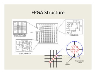
FPGA Structure and Design Flow Guide
- 3. Design Flow • Synthesis: HDL to FPGA primitives • Translate: FPGA Primitives to FPGA Slice components • Map: Packing of Slice components into Slices, placement of Slices on fabric • Route: connecting Slices • Bitstream generation: generating the required configuration bits to load into the FPGA
- 5. Slice LUTs • 1 CLB = 2 Slices • 1 Slice = 4 “LUT Modules”, 2 MUXF7, 1 MUXF8 • A LUT Module contains: 1 LUT6, 1 MUXCY, 1 XORCY, 2 FFs
- 6. Slice LUTs • 1 CLB = 2 Slices • 1 Slice = 4 “LUT Modules”, 2 MUXF7, 1 MUXF8 • A LUT Module contrains: 1 LUT6, 1 MUXCY, 1 XORCY, 2 FFs
- 7. Slice LUTs • LUTs = Multiplexers – Data Inputs from the FPGA configuration bits – Selection inputs from user logic – For N-input LUT, 2N configuration bits A B A|B 0 0 0 0 1 0 1 0 0 1 1 1 MUX 4:1 1 0 0 0 A B A|B
- 8. Slice LUTs • Number of LUT inputs is architecture dependent: – Xilinx Virtex 4 and earlier: 4-input LUTs (LUT4), 2 LUTs per Slice – Xilinx Virtex 5 and later: 6-input LUTs (LUT6), 4 LUTs per Slice – Xilinx Virtex 6 and 7-Series: 6-input LUTs, configurable as two shared-input 5-input LUTs – Altera: 8-input LUTs (ALM), configurable as combinations of smaller LUTs
- 9. Area and Delay vs. LUT Size • LUTs have constant delay, regardless of implemented function • Example: – LUT4 architecture (Virtex4) – O = I1 & I2 & I3 & I4 => 1 LUT, 0.43 ns – O = I1 & I2 & I3 & I4 & I5 & I6 => 2 LUTs, 0.93 ns • As a general rule: LUT delays are small, routing delays can be large
- 10. Exercise: Multiplexers • Implementation of 2:1, 4:1, 8:1 multiplexers on Virtex-4 architecture • Advanced multiplexing techniques: XAPP522
- 11. Slice Multiplexer Resources • A slice contains multiplexers that mux between LUT outputs (MUXFx) • Virtex-4: MUXF5 • Virtex-5 and later: MUXF7, MUXF8
- 12. Logic optimization using MUXFx • Example: – LUT4 architecture (Virtex4) – O = I1 & I2 & I3 & I4 & I5 => 1 LUT, 1 MUXF5, 0.72ns • Use of MUXFx reduces LUT usage and routing requirements • Local (in-Slice) routing -> more predictable performance
- 13. Logic optimization using MUXFx
- 14. Multiplexers vs First Index Decoders • Example code: always @* if(A) Out = E | F; else if(B) Out = E & F; else if(C) Out = E ^ F; else if(D) Out = ~E | F; else Out = 1'bx;
- 15. Multiplexers vs First Index Decoders
- 16. Multiplexers vs. First Index Decoders • The synthesis tool cannot always detect properties of the inputs of logic functions – Inputs are from pins – Inputs are from memories (Block or Distributed) • Unconstrained version, for when we know {A,B,C,D} is one-hot: assign sel1 = ~(A | B); assign sel0 = B | D; always @* case({sel1,sel0}) 2'b00: Out = E | F; 2'b01: Out = E & F; 2'b10: Out = E ^ F; 2'b11: Out = ~E | F; endcase
- 17. Multiplexers vs. First Index Decoders
- 18. Exercise: Adder • LUT6 Architecture (7-Series) • Implement 4-bit adder optimally (carry-chain versus carry look-ahead)
- 19. Slice Arithmetic Resources • Carry-chain adder implementation
- 20. Slice Arithmetic Resources • Slice primitives: MUXCY, XORCY
- 21. Selecting Adder Type • Analysis of various adder types (Design and Performance Analysis of Various Adders using Verilog; M. SaiKumar, P. Samundiswary) • Ripple-carry (RCA) has hardware support in FPGA • Carry-save (CSA) / Carry-look-ahead (CLA) are first choice for VLSI • Assignment: compare RCA/CSA based Popcount – Implement Verilog for 16b input – Synthesize/Map – Record delay and LUT/Slice counts
- 22. Adder Inference • Synthesis tools will infer RCA • Multi-input adder implementation may be controlled through parentheses: – E = (A+B)+(C+D) results in tree – E= (A+(B+(C+D))) results in cascade
- 23. Optimization Example • Implementing an “increment” instruction in a processor ALU in Virtex-4 • Behavioral description in ISE 14.2 yields bad results for the following code: always @* if(sel) sum = a+b+carry_in; else sum = a+4'd1+carry_in; • 12 Slices, 1.5ns delay. Can we do better?
- 24. Optimization Results • Using LUT3s instead of LUT2s in the adder structure, we can hardcode a multiplexer that selects between operand b and constant “1” before XOR-ing with operand a • The rest of the structure is identical (MUXCY, XORCY) and built with primitive instantiation • Results: 2 Slices, 1ns delay
- 25. Slice Registers • Latch/FlipFlop primitives available within the Slice • Available control signals: Set/Reset, Clock Enable, Clock • Asynchronous/Synchronous Set/Reset – Set/Reset typically refers to synchronous – Clear/Preset refers to asynchronous • Primitives: FD{R/S/RS/C/P}{E}
- 26. Slice Registers Synchronous Asynchronous Set always @(posedge clock) if(set) q<=1; else q<=d; always @(posedge clock or posedge set) if(set) q<=1; else q<=d; Reset always @(posedge clock) if(reset) q<=0; else q<=d; always @(posedge clock or negedge reset) if(set) q<=0; else q<=d;
- 27. Using Clock Enables • Control signal priority determines implementation of the Flip-Flop primitive Example 1: Set before CE Example 2: CE before Set always @(posedge clk) if(set) q<=1; else if(ce) q<=d; always @(posedge clk) if(ce) if(set) q<=1; else q<=d;
- 28. Using Clock Enables • Example 1 Results: FDSE • Example 2 Results: FDE + LUT
- 29. Using Clock Enables • Flip-Flop primitives are architecture dependent • Example: always @(posedge clk) if(reset) q<=0; else if(set) q<=1; else if(ce) q <= d;
- 30. Using Clock Enables • Spartan-3: FDRSE • Virtex-6: LUT+FDR
- 31. Using Clock Enables • Another example: always @(posedge clk) if(set) q<=1; else if(reset) q<=0; else if(ce) q <= d;
- 33. Async vs Sync Resets • Asynchronous resets – Act immediately – Are clock-independent – Induce timing hazards • Synchronous resets – Ports can be used to minimize logic – Predictable
- 34. Global Resets • We use global resets to: – Get the circuit into a known state at power-up – Initialize simulations properly (!) • Global resets have to be routed to S/R pins of the Flip-Flop • FPGAs include a dedicated global set-reset net for post-configuration initialization (GSR)
- 35. Using the GSR STARTUP_VIRTEX6 #( .PROG_USR("FALSE") // Activate program event security feature ) STARTUP_VIRTEX6_inst ( .CFGCLK(CFGCLK), // 1-bit Configuration main clock output .CFGMCLK(CFGMCLK), // 1-bit Configuration internal oscillator clock output .DINSPI(DINSPI), // 1-bit DIN SPI PROM access output .EOS(EOS), // 1-bit Active high output signal indicating the End Of Configuration. .PREQ(PREQ), // 1-bit PROGRAM request to fabric output .TCKSPI(TCKSPI), // 1-bit TCK configuration pin access output .CLK(CLK), // 1-bit User start-up clock input .GSR(GSR), // 1-bit Global Set/Reset input (GSR cannot be used for the port name) .GTS(GTS), // 1-bit Global 3-state input (GTS cannot be used for the port name) .KEYCLEARB(KEYCLEARB), // 1-bit Clear AES Decrypter Key input from Battery-Backed RAM (BBRAM) .PACK(PACK), // 1-bit PROGRAM acknowledge input .USRCCLKO(USRCCLKO), // 1-bit User CCLK input .USRCCLKTS(USRCCLKTS), // 1-bit User CCLK 3-state enable input .USRDONEO(USRDONEO), // 1-bit User DONE pin output control .USRDONETS(USRDONETS) // 1-bit User DONE 3-state enable output );
- 36. Avoid Latches! • Latches are most commonly generated by unterminated control sequences – Missing “else” statements in “if” clauses – Missing “default” statements in “case” clauses • To avoid over-constraining the logic, use “x” values in your “else” and “default” statements