(RIA) Call Girls Bhosari ( 7001035870 ) HI-Fi Pune Escorts Service
Adm
1. DIGITAL COMMUNICATION
T.R.K.N-SVEC Page 1
Unit – 2
2.1 DELTA MODULATION:
Delta Modulation is a special case of DPCM. In DPCM scheme if the base band signal is
sampled at a rate much higher than the Nyquist rate purposely to increase the correlation
between adjacent samples of the signal, so as to permit the use of a simple quantizing strategy
for constructing the encoded signal, Delta modulation (DM) is precisely such as scheme. Delta
Modulation is the one-bit (or two-level) versions of DPCM.
DM provides a staircase approximation to the over sampled version of an input base band signal.
The difference between the input and the approximation is quantized into only two levels,
namely, ± δ corresponding to positive and negative differences, respectively, Thus, if the
approximation falls below the signal at any sampling epoch, it is increased by δ. Provided that
the signal does not change too rapidly from sample to sample, we find that the stair case
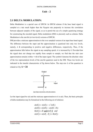
approximation remains within •± δ of the input signal. The symbol δ denotes the absolute value
of the two representation levels of the one-bit quantizer used in the DM. These two levels are
indicated in the transfer characteristic of fig shown below. The step size Δ of the quantizer is
related to δ by Δ = 2δ
Let the input signal be x(t) and the staircase approximation to it is u(t). Then, the basic principle
of delta modulation may be formalized in the following set of relations:
2. DIGITAL COMMUNICATION
T.R.K.N-SVEC Page 2
where Ts is the sampling period; e(nTs) is a prediction error representing the difference between
the present sample value x(nTs) of the input signal and the latest approximation to it, namely
̂(nTS)=u(nTs-Ts).The binary quantity, b(nTs) is the one-bit word transmitted by the DM
system.
The transmitter of DM system is shown in the figure. It consists of a summer, a two level
quantizer, and an accumulator. At each sampling instant, the accumulator increments the
approximation to the input signal by •± δ, depending on the binary output of the modulator.
In the receiver, shown in fig, the stair case approximation u(t) is reconstructed by passing the
incoming sequence of positive and negative pulses through an accumulator in a manner similar
to that used in the transmitter. The out-of –band quantization noise in the high frequency
staircase waveform u(t) is rejected by passing it through a low-pass filter with a band-width
equal to the original signal bandwidth.
3. DIGITAL COMMUNICATION
T.R.K.N-SVEC Page 3
Delta modulation systems are subject to two types of quantization error:
Slope –overload distortion, and
Granular noise.
If we consider the maximum slope of the original input waveform x(t), it is clear that in
order for the sequence of samples{u(nTs)} to increase as fast as the input sequence of samples
{x(nTs)} in a region of maximum slope of x(t), we require that the condition shown in equation
be satisfied.
Otherwise, we find that the step size Δ = 2δ is too small for the stair case approximation
u(t) to follow a steep segment of the input waveform x(t), with the result that u(t) falls behind
x(t). This condition is called slope-overload, and the resulting quantization error is called slope-
overload distortion (noise). Since the maximum slope of the staircase approximation u(t) is fixed
by the step size Δ , increases and decreases in u(t) tend to occur along straight lines. For this
reason, a delta modulator using a fixed step size is often referred as linear delta modulation
(LDM).
The granular noise occurs when the step size is too large relative to the local slope
characteristics of the input wave form x(t), thereby causing the staircase approximation u(t) to
hunt around a relatively flat segment of the input waveform; The granular noise is analogous to
quantization noise in a PCM system. The choice of the optimum step size that minimizes the
mean-square value of the quantizing error in a linear delta modulator will be the result of a
compromise between slope overload distortion and granular noise.
4. DIGITAL COMMUNICATION
T.R.K.N-SVEC Page 4
Conditions for slope over distortion: Consider the sinusoidal signal, x(t) = Am cos(2Лfmt)
It may be noted that slope of the signal x(t) will be maximum when derivative of x(t) w.r.t ‘t’
will be maximum.
The slope of DM may be given as,
We know that slope over load takes place if slope of sine wave is greater than slope of DM.
Note:
1. Slope over load takes place
2. No slope overload error occur for this condition
5. DIGITAL COMMUNICATION
T.R.K.N-SVEC Page 5
2.2 ADAPTIVE DELTA MODULATION:
The performance of a delta modulator can be improved significantly by making the step size of
the modulator assume a time-varying form. In particular, during a steep segment of the input
signal the step size is increased. Conversely, when the input signal is varying slowly, the step
size is reduced. In this way, the size is adapted to the level of the input signal. The resulting
method is called adaptive delta modulation (ADM).
There are several types of ADM, depending on the type of scheme used for adjusting the step
size. In this ADM, a discrete set of values is provided for the step size.
6. DIGITAL COMMUNICATION
T.R.K.N-SVEC Page 6
In practical implementations of the system, the step size Δ(nTs) or 2δ(nTs) is constrained to lie
between minimum and maximum values. The upper limit, δ max controls the amount of slope-
overload distortion. The lower limit, δ min, controls the amount of idle channel noise.
The upper limit, δ max controls the amount of slope-overload distortion. The lower limit, δ min
controls the amount of idle channel noise. Inside these limits, the adaptation rule for δ(nTs) is
expressed in the general form δ(nTs) = g(nTs). δ(nTs – Ts)
where the time-varying multiplier g(nTs) depends on the present binary output b(nTs) of the
delta modulator and the M previous values b(nTs-Ts), b(nTs-2Ts),………. b(nTs-MTs).
2.3 Comparison of Digital Pulse Modulation
Sl.
No.
Parameter PCM DPCM DM ADM
1. No of bits
per sample
4 or 8 or 16
bits used per
sample
More than one
bit but less
than pcm
Only one bit
per sample
Only one bit
per sample
2. Step size Depends on
the number
of bits
fixed Fixed can’t
be varied
Adaptive i.e.,
variable
depending up
on the signal
variation
3. Band width High Less than pcm Low Low
4. Generation Complex Simple Simple Simple
5. SNR Good 12db greater
than pcm
Poor Better
6. Quantization
noise or
distortion
Depends on
number of
levels used
Both
quantization
& Slope over
load occurs
Slope over
load &
granular
noise occurs
Only
quantization
error occurs
7. Sampling
rate
8Khz 8Khz 64-128Khz 48-64Khz
8. Bit rate 7-8,thus high
bit rate pcm
is superior
4-6 1, so it is
suitable for
low bit rate
1, so it is
suitable for low
bit rate
9. Application Telephony Audio and
speech
processing
Audio and
speech
processing
Audio and
speech
processing