Iaetsd modelling of one link flexible arm manipulator using
Control Bus Suspension Using PI and PID Controllers
1. CONTROL OF VEHICLE SUSPENSION SYSTEM USING
PI AND PID CONTROLLER
VENKATA SIRISH KUMAR.A NITHYA SANNAREDDY
Electrical Engineering Electrical Engineering
Gannon University Gannon University
Erie, Pennsylvania Erie, Pennsylvania
alahari001@knights.gannon.edu sannared001@knights.gannon.edu
Abstract— this paper presents the application of
PI and PID controller to control the shaking
occurred in the bus suspension system. When the
suspension system is designed, a one-fourth model
of bus is used to simplify the problem to a one
dimensional mass Spring- damper system. Its
open-loop performance on the basis of time
response is observed which shows that the bus
suspension has oscillations with large settling time.
To prevent this problem, closed-loop system is
used. Despite continuous advancement in control
theory, Proportional –Integral (PI) and
Proportional-Integral-Derivative (PID)
Controllers are used to control the shakings to
give smooth response of the bus suspension system
and carry-out their comparison on the basis of
time and frequency using MATLAB environment.
The simulation and implementation of the
controller is done using MATLAB/SIMULINK.
Keywords- Bus suspension system, dynamic
modeling, Proportional-Integral controller and
Proportional-Integral-Derivative controller.
I. INTRODUCTION
Increasing progress in automobile industry
demands for better riding capabilities and passenger
comfort, to produce highly developed model. The
aim of the advanced bus suspension system is to
provide smooth ride and maintain the control of the
vehicle over cracks, uneven pavement of the road.
Moreover, suspension system modeling has an
important role for realistic control design of
suspension
In passive suspension system, spring and
diminishing element is placed between the wheel and
the bus body. They allow the forward compensation
between the suspension stroke deviation and the
driving comfort. According to the bus structural
feature, suspension stroke is limited for some
specified values. Riding comfort reduces as
suspension deviation reached these limited specified
values. In active suspension system, a hydraulic
system which is controlled by feedback controller is
placed between the wheel and the bus body.
Controlled suspension system allows forward
compensation between the performance criteria of
suspension deviation and the riding comfort
Nowadays, different types of controllers are used
to control the bus suspension systemsuch as adaptive
control, LQG, nonlinear control, H infinity, P, PI and
PID. In this paper, PI and PID controllers are
designed to control the vibration occurred in bus
suspension systemusing SIMULINK/MATLAB
This paper is organized as follows: Firstly
Devoted to the bus suspension system.
The simulation implementation of open loop
systemand modeling is also presented in this section.
And also gives the introduction of PI and PID
Controllers, applies the PI and PID Controllers to the
bus suspension system.
II.THE BUS SUSPENSION SYSTEM
Bus Suspension is the systemof springs,shock
absorbers and linkages that connects a bus to its
wheels and allows relative motion between the two.
Suspension systemserves a dual purpose-
contributing to the vehicle's road holding/handling
and braking for safety purpose and pleasure driving,
and keeping vehicle occupants comfortable and
isolated from road noise, bumps, and vibrations, etc.
A. Modeling and System Analysis
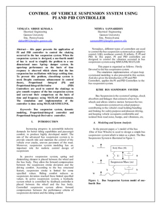
In the present paper, a ¼ model of the bus
(One of four Wheels) is used to design a simple bus
suspension systemwhich is taken as a plant. The Bus
Suspension Systemis illustrated in Figure 1.
Figure 1. Bus Suspension System model of one-
fourth Bus
2. From the bus suspension system model, we can
directly get the dynamic equation by using the
Newton’s law.
where M is the mass of body, m is the mass of
suspension system, K is the spring constant of
suspension system, k is the spring constant of wheel
and tyro, B is the damping constant of suspension
system, b is the damping constant of wheel and tyre,
U is the force from the controller which is to be
controlled .
Equations of Motion of quarter-bus model, given
in equations (1) and (2) has been transformed in
state-space model, shown in equations (3) and (4)
including variable vector, disturbance vector and the
input vector by applying some algebraic operations
on them.
In this paper, the distance X1-X2 instead of X1-W
is used as output as the distance X1-W is very
difficult to measure and the deformation of tire
(X2-W) is negligible.
B. Controllability and Observability
Open loop systemusing state space representation
can be described by state equation and output
equation given as
Where X is state vector of the system, U is control
signal, Y is output signal, A is n×n state matrix (n is
the number of states or order of system), B is n×1
input matrix, C is 1×n output matrix, D is direct
transmission matrix (scalar).
1) Controllability
A systemis said to be controllable if it is
possible by means of input vectorU(t), to take a
systemfrom any initial state X(ti) to any final state
X(to) in a finite time (t0 - ti) where ti ≤t≤t0. For a
completely controllable systemevery state must be
controllable.
Based on controllability matrix Ct, a system
given by equations (5) and (6) is said to be
completely controllable if and only if the rank of
controllability matrix Ct is equals to the order of
system.
A systemis said to be stabilizable if matrices A and
B are controllable. In the present paper, the rank of
controllability matrix is 4, the order of the system,
and hence systemis completely state controllable.
2) Observability
An unforced system(input vector U (t) = 0)
is said to be completely observable if any initial state
X (ti) can be determined by the observation of output
Y (t) over a finite interval ti ≤ t ≤ t1.Sometimes all
state variables are not accessible for direct
measurement, in such situations the concept of
observability is very useful to reconstruct
immeasurable state variables form the measurable
variables in a very short period of time.
Based upon observability matrix Ot, a system
described by state space equations (3) and (4) is said
to be completely observable if and only if the rank of
observability test matrix Ot is equals to the order of
system.
A systemis detectable if matrices A and C are
observable.For the systemgiven, the rank of
observability matrix is 4which is equal to the order of
systemhence from the observability test theorem the
systemis completely observable.
3. III.CONTROLLER
A controller is a device, may be in the form of
analogue circuit, chip or computer that monitors and
physically alters the operating conditions of a given
dynamical system.
From the past decades,the importance of the control
systemhas been increased due to the increment in
complexity of the systemunder control and to
achieve optimum performance of the system. The
block diagram of closed-loop Bus Suspension System
is shown in Figure 2.
In this paper, two controllers, Proportional-
Integral (PI) Controller and Proportional-Integral-
Derivative (PID) Controller are used to improve the
response ofthe system.
Figure2. step response of Bus Suspension System
A. Proportional-Integral Controller
The combination of proportional and integral
terms is important to increase the speed of the
response and also to eliminate the steady state error.
C(s) the transfer function of PI controller has the
form of
The PID controller block is reduced to P and I
blocks only as shown in figure 3.
Figure 3. Block Diagram of PI controller
Where, KP is proportional gain and KI is an
Integral gain. The proportional term (sometimes
called gain) makes a Change to the output that is
proportional to the current Error value. The
proportional response can be adjusted by multiplying
the error by a constant Kp, called the proportional
gain.
The contributes from the integral term
Sometimes cal led reset is proportional to both the
Magnitude of the error and the duration of the error.
Summing the instantaneous errorover time gives the
accumulated offset that should have been corrected
previously. The accumulated error is then multiplied
by the integral gain and added to the controller
output.
B. Proportional-Integral-Derivative Controller
A proportional-integral-derivative controller
(PID controller) is a generic control loop feedback
mechanism widely used in industrial control systems
- a PID is the most commonly used feedback
controller. A PID controller calculates an "error"
value as the difference between a measured process
variable and a desired set point. The controller
attempts to minimize the error by adjusting the
process controlinputs.
In this section, the method to obtain the controller
for the bus suspension systemis described when a
PID scheme is used to perform control actions and
C(s) the transfer function of PID controller has a
form.
The block diagram of the PID controller is shown in
Figure 4
Figure 4. Block Diagram of PID controller
The PID controller calculation involves three
separate parameters, and is accordingly sometimes
called three-term control: the proportional, the
integral and derivative values, denoted P, I, and D.
The proportional value determines the reaction to the
current error, the integral value determines the
reaction based on the sum of recent errors, and the
derivative value determines the reaction based on the
rate at which the error has been changing.The
weighted sum of these three actions is used to adjust
the process via a control element such as the
disturbances ofa bus suspension system.
4. IV.CONCLUSION
In this paper, PI and PID Controllers have been
outlined and utilized for controlling a suspension
arrangement of a ¼ transport model. The proposed
model is planned to created and convey the reaction
of framework utilizing PID controller up to a superior
level.
REFERENCES
[1] K. Matsumoto, K. Yamashita and M. Suzuki,
“Robust H∞ -output feedback control of decoupled
automobile active suspension system”,IEEE
Transaction on Automatic Controller, vol. 44,
pp.392-396, 1999.
[2] Elmadany, M., “Integral and state variable
feedback controllers for improved Performance in
automotive vehicles”, Computer Structure.,
vol. 42, no. 2, pp. 237-244, 1992.
[3] Isobe,T. and O. Watanabe,“New semi-active
suspension controllerdesign using quasilinearlization
and frequency shaping”,Control Eng.Pract., vol. 6,
pp. 1183-1191, 1998.
[4] D’Amato, F.J. and D.E. Viassolo, “Fuzzy control
for active suspension”,Mechatronics,vol. 10, pp.897-
920, 2000.
[5] Kim H.J, H.S. Yaug and Y.P. Park, “Improving
the vehicle performance with active suspension using
road-sensing algorithm”, Computers and Structure;
vol. 80, pp. 1569-1577, 2002.
[6] Spentzas K. and A.K. Stratis “Design of a non-
linear hybrid car suspension systemusing neural
network”, Mathematics and Computers in
Simulation, vol. 60, pp. 369- 378, 2002.
[7] Yao, G. Z., F. F. Yap, G. Chen, W. H. Li and S.
H. Yeo, “MR damper and its application for semi-
active control of vehicle suspension system”,
Mechatronics,vol. 12, pp.963-973, 2002.
[8] Gordon, T. J., Marsh, C., and Milsted, M. G., "A
Comparison of Adaptive LQG and Nonlinear
Controllers for Vehicle Suspension Systems”,
Vehicle SystemDynamics, pp. 321-340, 1991.
[9] Kuo Y. P. and T. H. S. Li, “GA-Based Fuzzy
PI/PID Controller for Automotive Active Suspension
System”, IEEE Transactions on Industrial
Electronics, vol. 46, pp. 1051–1056, December 1999.
[10] Zhuang,M. and D. P. Atherton, “Automatic
tuning of optimum PID controllers,” IEEE
Proceeding Part D, vol. 140, pp. 216-224, 1993.