Downloaded 20 times
![International Journal of Research in Engineering and Science (IJRES)
ISSN (Online): 2320-9364, ISSN (Print): 2320-9356
www.ijres.org Volume 3 Issue 7 ǁ July. 2015 ǁ PP.40-47
www.ijres.org 40 | Page
Study of Pneumatic Speed Control System with Friction Force
Compensation
Ye Yizhou1
, Wang Wenjin 2
, Chen Xing1
1
(College of Mechanical Engineering, Shanghai University of Engineering Science, Shanghai, China)
2
(Shanghai Jiaoyun Auto Power Components Co., Ltd, Shanghai, China)
ABSTRACT: In this paper, the mathematical model of pneumatic speed control system was established and
simulated through Matlab/Simulink. The conclusion that cylinder friction force must be compensated was
provided after analyzing the simulation results. Some performance of the system could be improved in low cost
through adding chatter signal to control signal to compensate cylinder friction force and combining with PID
control.
Keywords - chatter signal, friction force compensation, mathematical model, speed control, simulation
I. INTRODUCTION
Pneumatic technology is a low cost automation. It has the characteristics about simple structure, clean,
working reliably, easy to control and convenient maintenance. At present, pneumatic technology has been
widely used in manufacture [1]
. Due to the factors of gas compressibility, cylinder friction force and the flow-
pressure characteristics of control valve, precise pneumatic speed control is difficult to achieve. Among them,
cylinder friction force is the most important factor [2]
. At present, almost all of the research on pneumatic speed
control is utilizing control strategy to compensate cylinder friction force [3]
. These are too complex and high-cost
to make them widely used. This paper shows a method to improve the performance of the system through
adding chatter signal to compensate cylinder friction force and combining with PID control.
II. MATHEMATICAL MODEL OF THE PNEUMATIC SPEED CONTROL SYSTEM
This system adopts electric-pneumatic proportional valve, the model of system is shown in Fig.1.
Fig.1 The Model Diagram of System
The gas is assumed as ideal gas, and its flow process is isentropic [4]
. The structure of valve spool is slide
valve. All of valve spool and piston move to right. The gas flows into the chamber “a” of the cylinder and flows](https://image.slidesharecdn.com/h374047-150822070344-lva1-app6891/75/Study-of-Pneumatic-Speed-Control-System-with-Friction-Force-Compensation-1-2048.jpg)
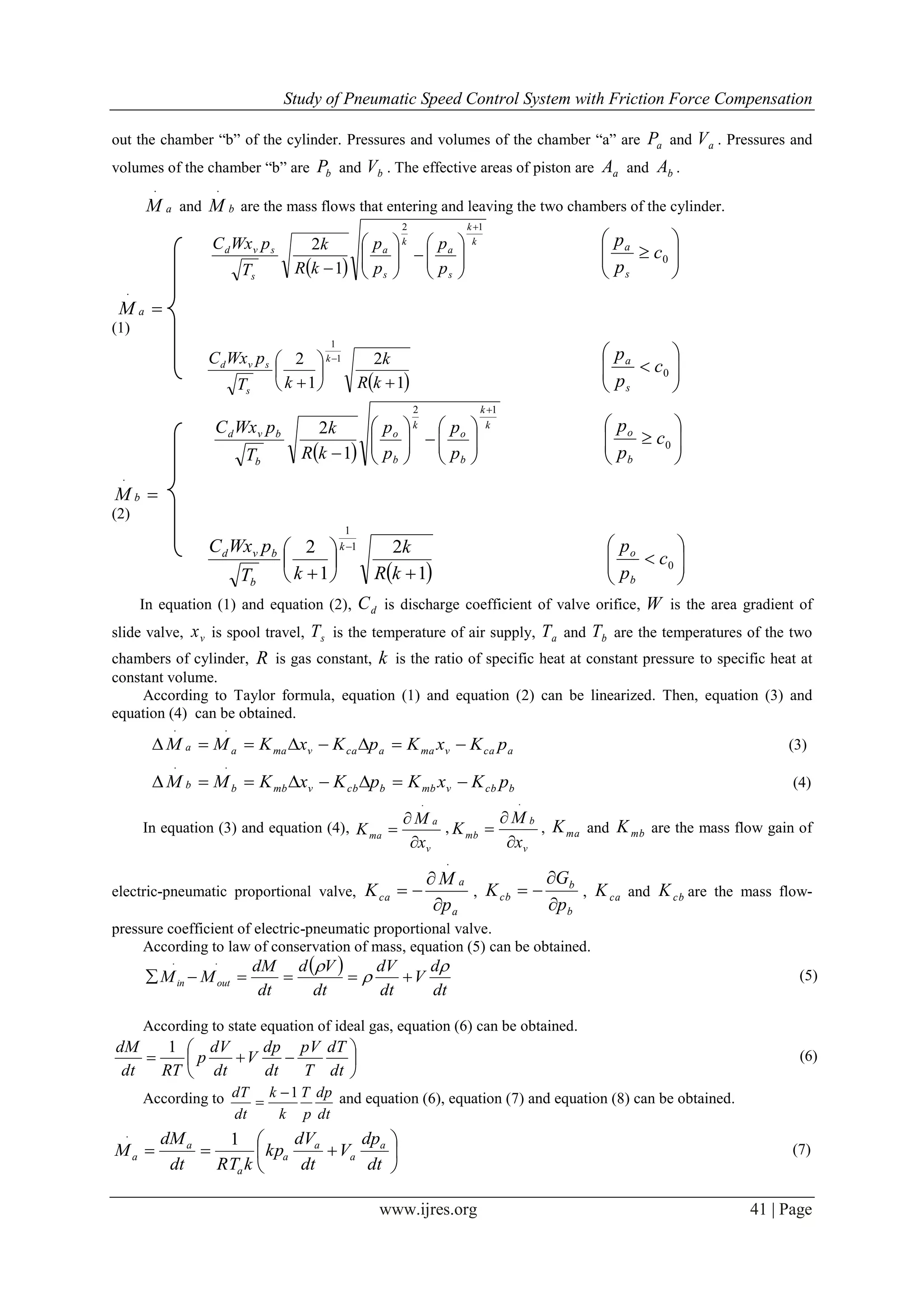
![Study of Pneumatic Speed Control System with Friction Force Compensation
www.ijres.org 42 | Page
dt
dp
V
dt
dV
kp
kRTdt
dM
M b
b
b
b
b
b
b
1
(8)
It is generally believed that the performance of pneumatic system is worst when the initial position of
piston is middle of cylinder stroke [5]
.
This paper assumes that
aa MM 0 , aaaia yAVV ,
bb MM 0 , yAVV bbib ,
bibaia pApA ,
a
b
A
A
n , aibi p
n
p
1
, aa VV 0 , bb VV 0 ,
a
b
V
V
m
0
0
, sbiai TTT . According to
equation (7) and equation (8), equation (9) and equation (10) can be obtained.
dt
dp
V
dt
dy
Akp
kRT
m a
aaai
s
a 0
1
(9)
dt
dp
mV
dt
dy
nAp
n
k
kRTdt
dp
V
dt
dy
Akp
kRT
m b
aaai
s
b
bbbi
s
b 00
111
(10)
The force balance equation of cylinder is equation (11).
nppAFyK
dt
dy
k
dt
yd
MApAp baaLLLbbaa 2
2
(11)
In equation (11), LM is the total mass of piston and load, k is viscous damping coefficient, LK is load
spring stiffness, 0LK , LF is disturbing force, 0 sPsF bL .
Through equation (3), equation (4), equation (9) and equation (10), equation (12) can be obtained.
dt
dy
Akp
m
n
dt
dp
V
kRT
pnKK
m
n
pKxK
m
n
K aai
La
a
s
bcacbLacavmbma 1
1
0
(12)
In equation (12), baLa nppp . Through Laplace transform, equation (12) and equation (11) can be
respectively transformed into equation (13) and equation (14).
ssYAp
m
n
RT
sPnKK
m
n
sXK
m
n
KsP
kRT
sV
K aai
s
bcacbvmbmaLa
s
a
ca
1
10
(13)
sFsYKsksMsPA LLLLaa
2
(14)
Through equation (13) and equation (14), the block diagram of system can be obtained, it is shown in
Fig.2.
Fig.2 The Block Diagram of System
From Fig.2, the transfer function that spool travel as input and piston displacement as output can be
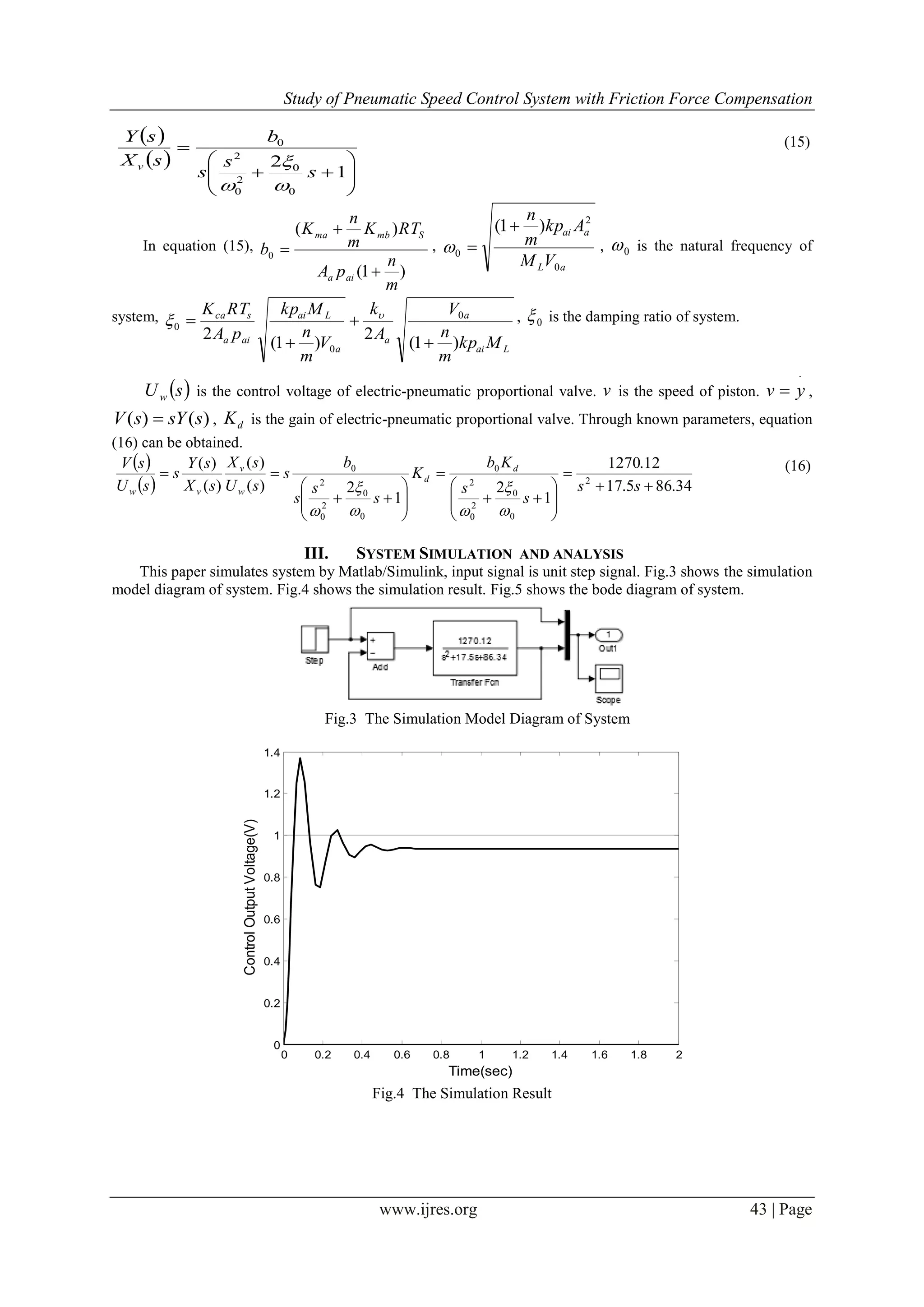
obtained. sX v is spool travel, sY is piston displacement. The transfer function is equation (15).](https://image.slidesharecdn.com/h374047-150822070344-lva1-app6891/75/Study-of-Pneumatic-Speed-Control-System-with-Friction-Force-Compensation-3-2048.jpg)
![Study of Pneumatic Speed Control System with Friction Force Compensation
www.ijres.org 44 | Page
-60
-40
-20
0
20
40
Magnitude(dB)
10
-1
10
0
10
1
10
2
10
3
-180
-135
-90
-45
0
Phase(deg)
Bode Diagram
Gm = Inf dB (at Inf rad/s) , Pm = 28.5 deg (at 34.7 rad/s)
Frequency (rad/s)
Fig.5 Bode Diagram
From Fig.4, it can be known that the system transient response is not perfect. The overshoot of system is
36.98%, it is excessive. The steady-state error of system is 6.3%. The time that system reaches stable state is
0.777s.
From Fig.5, it can be known that the stability margin of system is 1inf . The phase stability margin of
system is 05.28
. It is easy to know that the system is stable in open-loop condition, so the system is stable.
The overshoot of system is mainly caused by the friction force mutation of cylinder [5]
. Especially, when
system is operating at low speed, the friction force mutation of cylinder will cause the crawling phenomenon of
cylinder [6-7]
. This crawling phenomenon will cause speed fluctuation and reduce the performance of system [8]
.
The friction force mutation of cylinder is caused by the difference between the coefficient of static friction
and the coefficient of kinetic friction. If this difference had been reduced or eliminated, the generation of this
crawling phenomenon would be reduced or disappeared.
Through adding chatter signal to control signal, some or all of the static friction force of cylinder will
become the kinetic friction force of cylinder [9]
. Then, the difference between the coefficient of static friction
and the coefficient of kinetic friction will be reduced or eliminated, so the generation of the crawling
phenomenon of cylinder will be reduced or disappeared.
The chatter signal is sine signal with high frequency and low amplitude, it is tA sin and
2
00 21 .
In this paper, there are two different chatter signals that be respectively added to control signal. These two
control strategies are respectively called “1#” and “2#”. Fig.5 shows the simulation model diagram of system
with cylinder friction force compensation. Fig.6 shows the simulation results of system with cylinder friction
force compensation. From Fig.6, simulation results table can be obtained, it is Table.1. In Table.1, Ts is the
time that system reaches stable state.](https://image.slidesharecdn.com/h374047-150822070344-lva1-app6891/75/Study-of-Pneumatic-Speed-Control-System-with-Friction-Force-Compensation-5-2048.jpg)
![Study of Pneumatic Speed Control System with Friction Force Compensation
www.ijres.org 45 | Page
Fig.5 The Simulation Model Diagram of System with Cylinder Friction Force Compensation
0 0.2 0.4 0.6 0.8 1 1.2 1.4 1.6 1.8 2
0
0.2
0.4
0.6
0.8
1
1.2
1.4
Time(sec)
ControlOutputVoltage(V)
1#
2#
1#: be added with 0.001sin1000t
2#: be added with 0.001sin1000t-0.15
Fig.6 The Simulation Results of System with Cylinder Friction Force Compensation
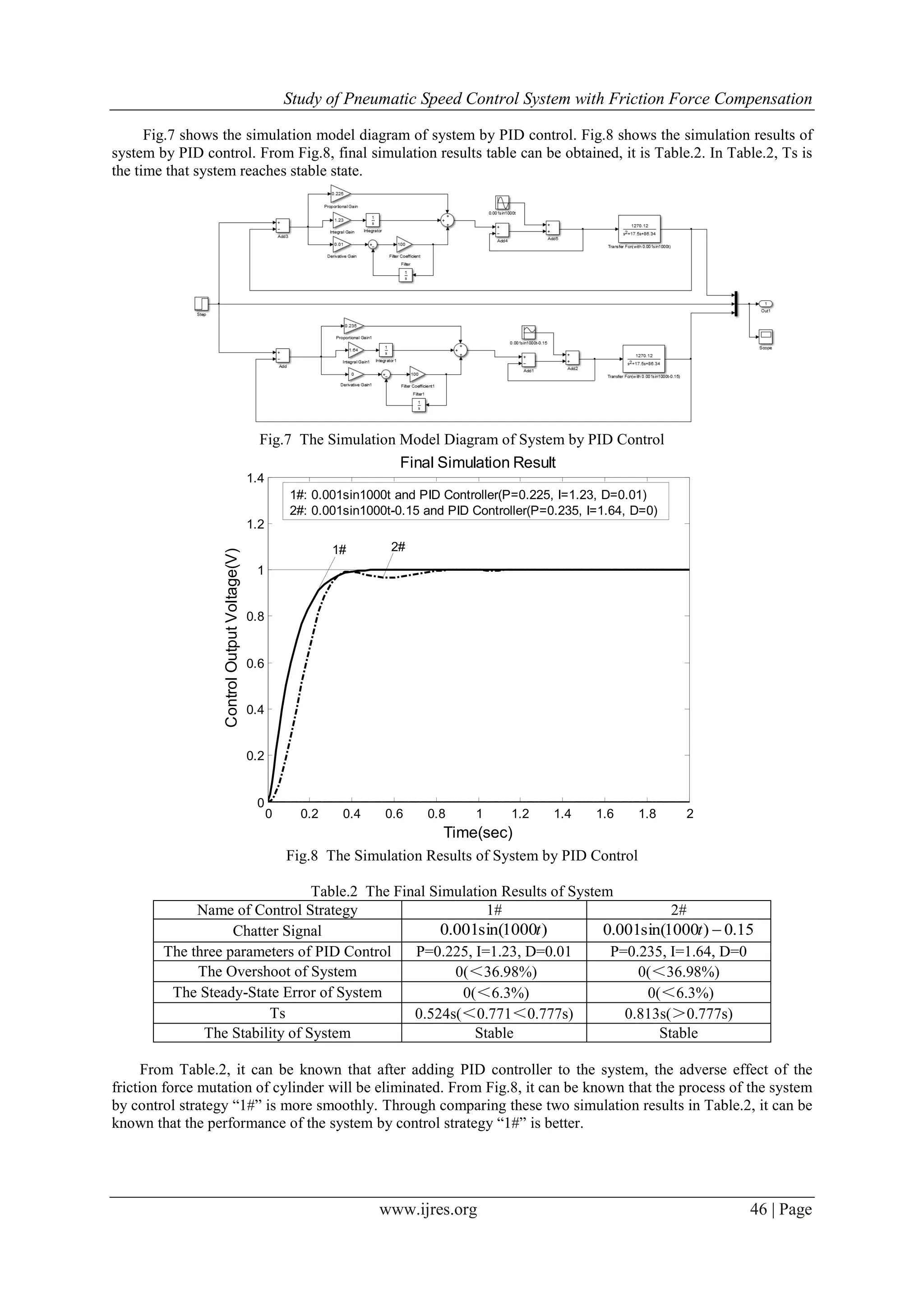
Table.1 The Simulation Results of System
Name of Control Strategy 1# 2#
Chatter Signal )1000sin(001.0 t 15.0)1000sin(001.0 t
The Overshoot of System 17.78%(<36.98%) ≈0(<36.98%)
The Steady-State Error of System 11.9%(>6.3%) 25.175%(>6.3%)
Ts 0.771s(<0.777s) 0.771s(<0.777s)
The Stability of System Stable Stable
From Table.1, it can be known that after adding chatter signal to control signal, the adverse effect of the
friction force mutation of cylinder will be eliminated or partial eliminated. This can improve the speed of
system response, but the steady-state error of system will be increased. So, the system needs to combine with
other control strategy to eliminate the steady-state error of system.
This paper adopts PID control to eliminate the steady-state error of system. According to the situation of
system, people only need to adjust three parameters of PID control. These three parameters are Proportion (P),
Integral (I) and Differential (D), respectively. PID control compares with other control strategies, it is simpler
and more used widely. PID control has the characteristics about simple algorithm, good robustness, good
reliability. PID control has occupied more than 95% of the field of industrial control [10]
. At present, there are a
lot of mature PID hardware controllers on the market. They can be used in practice at low cost.](https://image.slidesharecdn.com/h374047-150822070344-lva1-app6891/75/Study-of-Pneumatic-Speed-Control-System-with-Friction-Force-Compensation-6-2048.jpg)
![Study of Pneumatic Speed Control System with Friction Force Compensation
www.ijres.org 47 | Page
IV. CONCLUSION
Achieving precise control of pneumatic speed can further expand the scope of application of pneumatic
technology. But at present, the research documents of pneumatic speed control are relatively less. This paper
belongs to preliminary exploration about pneumatic speed control. Cylinder friction force is the most important
factor that makes pneumatic system difficult to achieve precise speed control. The friction force mutation of
cylinder mainly refers to the transition between the kinetic friction force of cylinder with the static friction force
of cylinder, it can cause speed fluctuation. Especially in the state of low speed, this mutation can cause the
crawling phenomenon of cylinder. That will affect the precision of speed control and reduce the performance of
system. Through adding chatter signal to control signal, part of the friction force mutation of cylinder can be
eliminated, this can compensate part of the adverse effects of cylinder friction force. Then through combining
with PID control, the steady-state error of system and the rest of the adverse effects of cylinder friction force
will be eliminated. This control strategy can effectively restrain pneumatic speed fluctuation and the generation
of the crawling phenomenon of cylinder. Be compared with other control strategies, this control strategy can
achieve similar control effect at low cost, and it is relatively simpler. So, this control strategy has good practical
value.
REFERENCES
[1] Wang Jiwei, Zhang Hongjia, Huang Yi, Hydraulic and Pneumatic Transmission (Beijing, China Machine Press, 2013).
[2] Jiang Zhouyong, Li Zuoli, Cylinder Friction Force Compensation and Simulation Research Base on Matlab, Coal Engineering,
2007(1).
[3] Qiu Zhicheng, Wang Bin, Direct Adaptive Fuzzy Control of a Translating Piezoelectric Flexible Manipulator Driven by a
Pneumatic Rodless Cylinder, Mechanical Systems and Signal Processing, 2013(36), 290~316.
[4] Wu Zhengsun., Pneumatic Transmission and Control (Harbin, Harbin Institute of Technology Press, 2010).
[5] SC Fok, Position Control and Repeatability of a Pneumatic Rodless Cylinder System for Continuous Positioning, Robotics and
Computer Integrated Manufacturing, 1999(15), 365~371.
[6] Ciliz MK, Omizuka M, Neural Network Based Friction Compensation in Motion Control, Electronics Letters, 40(12), 2004,
752-753.
[7] Bender FA, Ampaert V, Modeling of Dry Sliding Friction Dynamics: From Heuristic Model to Physically Motivated Models and
Back, Chaos, 14, 2004, 446-460.
[8] Xie Zugang, Study of the Friction Force of the Cylinder in Low Speed, Zhejiang University, Zhejiang, 2003.
[9] Kong Xiangzhen, Liu Yanjun, Chatter Compensation and Simulation for the Pneumatic Cylinder with Friction, Lubrication
Engineering, 8(8), 2006.
[10] Hagglund T, A Friction Compensator for Pneumatic Control Valve, Journal of Process Control, 8(12), 2002, 97~99.](https://image.slidesharecdn.com/h374047-150822070344-lva1-app6891/75/Study-of-Pneumatic-Speed-Control-System-with-Friction-Force-Compensation-8-2048.jpg)

This study presents a mathematical model and simulation of a pneumatic speed control system that incorporates friction force compensation. The method improves system performance by adding a high-frequency chatter signal to the control input, thus reducing the impact of cylinder friction force and enhancing stability. Results demonstrate a significant reduction in overshoot and improved control response, particularly at low speeds.