SlideShare a Scribd company logo
1 of 14
Download to read offline
Checked by
DESIGN OF HEADED CONCRETE ANCHOR & END PLATE
SUPPORTING MEMBER RC BEAM
D1 = mm ha = mm
B1 = mm
SUPPORTED MEMBER HOPPER
SUPPORTED BEAM END FORCES
Factored
Compressive force C = kN
Tensile force T = kN
Vertical force = kN (~5000kg*9.81/1000)
Horizontal shear force = kN
Moment = kNm
CONNECTION DETAILS
Bolt details
Diameter of anchor do =
Diameter of Nut H =
Effective cross sectional area of one anchor Ase =
Nr of anchor column nc =
Nr of anchor rows nr =
Nr of bolts n =
Spacing of anchor rows (pitch) p =
Spacing of anchor columns (gauge) g =
Sum of square of 'r' for the bolt group e r
2
= r =
Effective anchor embedment depth hef =
Eccentricity & Edge distance
Horizontal Edge distance for nth column of bolts ca2 =
Horizontal Edge distance for 1st column of bolts ca4 =
Vertical Edge distance for nth row of bolts ca1 =
Vertical Edge distance for 1st row of bolts ca3 =
Edge distance bt. anchors and end plt. e'
=
Eccentricity for vertical shear e =
Eccentricity of normal force on group of anchors eN' =
(The distance between the resultant tension load on a group of anchors in tension and the centroid of the
group of anchors in tension)
Eccentricity of shear force on group of anchors, eV' =
(The distance between the resultant shear load on a group of anchors in shear and the centroid of the
group of anchors in shear)
0.0
1300.0
mm
Connection id
150.0 mm
32500.0
500.0
30.0 mm
90.14
2
mm2
150.0 mm
0.0
20.0
mm
0.0
50.0
314.2 mm
2
mm
1325.0 mm
100.0
1055.0 mm
0.0
2000.0
Designed by Date 20-Sep-14
100.0 mm
2
5000.0
4
0.0
50.0 mm
0.0 mm
SUBJECT
mm
95.0 mm
ANCHOR BOLT DESIGN
PROJECT
REFERENCE
A
ACI 318M-11
1 / 14
Checked by Connection id
Designed by Date 20-Sep-14
SUBJECT ANCHOR BOLT DESIGN
PROJECT
REFERENCE
A
ACI 318M-11
Depth supported member/fin plate Ds = mm
Thickness of fin plate/ supported member wed tf = mm
Distance between tension bolts to compression edge D = mm
mm
(ca3) Design strength reduction factor
f =
mm
(ca1)
mm mm
(ca2 ) (ca4 )
Plate details
Depth of end plate Dp =
Width of end plate Bp =
Thickness of end plate tp =
Material strength & grade
Grade of bolt =
Tensile Strength of bolt futa =
Characteristic strength of Concrete (cylinder) fc
'
=
Yield strength of plate fyp =
1325
12
250
250
2000
560.0
95
1055
N/mm
2
N/mm2
8.8 grade
200.0 mm
20.0 mm
250.0 mm
40.0
N/mm
2
0.75
265.0
2 / 14
Checked by Connection id
Designed by Date 20-Sep-14
SUBJECT ANCHOR BOLT DESIGN
PROJECT
REFERENCE
A
ACI 318M-11
CONNECTION CAPACITY CHECKS SUMMARY
TENSION LOAD
Remarks 2.5ca1>hef, Blow-out strength check is not required
SHEAR LOAD
INTERACTION OF TENSILE AND SHEAR LOADING
Interaction for single anchor (Nua/fNn+Vua/fVn) = <= 1.2 SAFE
Interaction for group of anchors (Nuag/fNng+Vuag/fVng) = <= 1.2 SAFE
PLATE
End plate thickness required = < tp SAFE
0.096
Concrete pryout strength of group of anchors 157.16 50.0 0.318 SAFE
Concrete pryout strength of an anchor 128.58 12.50 0.097 SAFE
Concrete breakout strength for group of anchors 253.80 50.00 0.197 SAFE
0.050
25.00
78.6
SAFE
SAFE
0.095
SAFE
Concrete breakout strength of an anchor 251.93 12.50
SAFE
Steel strength for group of anchors 527.79 50.00 0.095 SAFE
Steel strength of an anchor 131.95
Checks
Design values Utilization
Ratio
Capacity(kN) Load(kN)
Status
Concrete side-face blowout strength of anchor
Pullout strength of an anchor
Concrete breakout strength of an anchor
0.08
Concrete side-face blowout strength for group of
anchor
Pullout strength for group of anchors
Concrete breakout strength for group of anchors
N.A.
Steel strength for group of anchors
10.1
N.A.
263.88
0.08
N.A
MAXIMUM UTILIZATION RATIO
SAFE
10.10
0.16
20.2
12.50
0.58
20.20
10.10
SAFE
0.08 SAFE
SAFE
0.26
SAFE
0.25
20.20
10.10
20.2
N.A
Steel strength of an anchor
Concrete breakout strength for group of anchors
near concrete edge 260.59
131.95
SAFE
0.08
Capacity(kN) Load(kN)
Status
Design values Utilization
Ratio
Checks
263.89
64.29
131.94
0.32
15.12 20.0
SAFE
3 / 14
Checked by Connection id
Designed by Date 20-Sep-14
SUBJECT ANCHOR BOLT DESIGN
PROJECT
REFERENCE
A
ACI 318M-11
MAXIMUM FORCES IN ANCHORS
Shear force
Torsion due to horizontal eccentricity in shear Me = V*ev'
=
Shear force anchor due to moment Vh = Me*r/εr
2
=
Vertical shear due to Fm FVm = Fm * cosO O =
=
Horizontal shear due to Fm FHm = Fm * sin O
=
Shear force per anchor due to vertical force Vv = 50/4
=
Total Shear force per anchor Vua =
Shear force for group of anchors Vuag =
Tension force
Bearing strength of concrete = 0.85fcfc'
=
Force equilibrium for the design bearing stress T+N = C
Considering the moment equilibrium M = T(D-Dp/2)+C(Dp-X/2)
0.85fc'fcbpX(D-X/2)-Fy(D-Dp/2) = M
20.4*200*X(250-X/2)-0*(250-250/2) = 50* 0.1+0*0+0
2.04X^2-1020X+5000 =
a = b = c =
X1 = -(-1020)+(-1020^2-4*2.04*5000)^0.5/(2*2.04) =
X2 = -(-1020)-(-1020^2-4*2.04*5000)^0.5/(2*2.04) =
Length of compressive stress block X = mm
Compression force resisted by concrete C = kN
Tension force transfer to anchors T = kN
(Assumed to be transfer to anchors located
above the C.G. of end plate)
Nos of anchors row effective in tension nrt = (2 ) / 2
=
-1020
2.04 5000
0
495.05
4.95
0.0 kN.m
kN
12.5 kN
56.3
4.95
20.2
20.2
1.0
12.5 kN
50.0 kN
KN
0.00 KN
Assuming the shear transfer to anchors as below
MPa
20.4
0.00
0.0
4 / 14
Checked by Connection id
Designed by Date 20-Sep-14
SUBJECT ANCHOR BOLT DESIGN
PROJECT
REFERENCE
A
ACI 318M-11
Nos of anchors efective for tension nt = 2 * 1
=
Tension force on an anchor due to bending T1 = 20.2/ 2
T1 = kN
Direct tension force in each anchor T2 =
= kN
Total tension in each anchor, Nua = T1+T2
= kN
Tension force transfer to group of anchors Nuag =
= kN
STEEL STRENGTH OF ANCHORS
As per ACI 318-05 D5.1
Nominal strength of a single anchor in tension Nsa = Ase * futa
= 314.16*560/1000
=
As per ACI 318-05 D4.4 a(i) f =
f Nsa = >Nua SAFE
( )
Nominal strength of group of anchors in tension Nsag = nt * Ase * futa
= 2*314.16*560/1000
=
f Nsag = > Nuag SAFE
( )
CONCERE BREAKOUT STRENGTH OF ANCHOR
Single Anchor
min(ca3,1.5hef)
mm
min((ca1+(nr-1)p), 1.5hef)
mm
min(ca2, 1.5hef) min((ca4 +(nc-1)g), 1.5hef)
mm mm
As per ACI 318-05 D5.2
Nominal concrte breakout strength of an Ncb = ANc/ANco * yed,N * yc,N * ycp,N* Nb
anchor in tension
225
95
225
2.0
10.1
Nua*nt
20.2
0.75
175.9
0 / 4
0.0
10.1
kN
131.9 kN
10.1
351.9 kN
263.9 kN
20.2
225
CAPACITY AGAINST TENSION LOADING
5 / 14
Checked by Connection id
Designed by Date 20-Sep-14
SUBJECT ANCHOR BOLT DESIGN
PROJECT
REFERENCE
A
ACI 318M-11
Basic concrete breakout strength of an anchor Nb = kc sqrt(fc
'
) hef
1.5
in cracked concrete
For cast-in anchors kc =
Actual anchor embedment depth h1 =
ca,min = mm
ca,max = mm
Max(Cmax/1.5,max spacing/3) h2 = mm
Effective anchor embedment depth hef = If 1.5*h1>Cmax = h2 or h1
=
Nb = 10* sqrt(40) *150^1.5
Nb =
Modification factor for edge effects yed,N = 0.7 + 0.3 (ca,min/1.5hef) for ca,min <1.5hef
= for ca,min >1.5hef
yed,N =
Modification factor to account for cracking yc,N =
Modification factor to account for post-install ycp,N = For cast-in anchors
anchors
Projected concerte failure area of an anchor ANco = 9 hef
2
(not limited by edge distance or spacing) = 9 *150^2
=
Projected concerte failure area of an anchor = (225+95) * (225+225) < ANco
( limited by edge distance or spacing) =
ANc =
Nominal concrte breakout strength of an Ncb = (144000/202500) * 0.83*1.25*1*116.19
anchor in tension =
f Ncb = >Nua SAFE
( )
Group of anchors
Basic concrete breakout strength of an anchor Nb = kc sqrt(fc
'
) hef
1.5
in cracked concrete
For cast-in anchors kc =
Actual anchor embedment depth h1 =
ca,min = mm
ca,max = mm
Max(Cmax/1.5,max spacing/3) h2
Effective anchor embedment depth hef = If 1.5*h1>Cmax = h2 or h1
=
Nb = 10* sqrt(40) *150^1.5
= 116.2
10.0
150.0 mm
150.0 mm
95
225
0.83
1.25
1.00
202500.0 mm2
116.2 kN
1.0
10.1
144000.0 mm2
144000.0 mm
2
85.7 kN
kN
150 mm
150.0 mm
64.3 kN
150.0 mm
150
95
225
10.0
6 / 14
Checked by Connection id
Designed by Date 20-Sep-14
SUBJECT ANCHOR BOLT DESIGN
PROJECT
REFERENCE
A
ACI 318M-11
min(ca3, 1.5hef)
mm
(nrt-1)p = mm
min((ca1+(nr-1)p-(nrt-1)p), 1.5hef)
mm
min(ca2, 1.5hef) (nc-1)g min(ca4, 1.5hef)
mm mm mm
Modification factor for eccentrically loaded
anchor group yec,N = 1/(1 + (2e'N / 3hef))
Modification factor for edge effects = 0.7 + 0.3 (ca,min/1.5hef) for ca,min <1.5hef
= for ca,min >1.5hef
yed,N =
Modification factor to account for cracking yc,N =
Modification factor to account for post-install ycp,N = For cast-in anchors
anchors
Projected concerte failure area of an anchor ANco = 9 hef
2
(Not limited by edge distance or spacing) = 9 *150^2
=
Projected concerte failure area of group of = (95+0+225) * (225+100+225)
(Limited by edge distance or spacing) = < nt ANco
ANc = ( mm
2
)
Nominal concrte breakout strength for Ncbg = ANc/Anco yec,N* yed,N * yc,N * ycp,N* Nb
group of anchors in tension = (176000/202500) * 1*0.83*1.25*1* 116.19
=
f Ncbg = > Nuag SAFE
( )
PULLOUT STRENGTH OF ANCHOR
As per ACI 318-05 D5.3
Nominal pullout strength of an anchor Npn = yc,P * Np
in tension
Pullout strength in tension of an Np = Abrg * 8* fc
'
headed bolt or headed bolt
225 100
225
95
225
1.00
1.0
78.6 kN
0.83
1.25
1.00
202500.0 mm
2
176000.0 mm2
20.2
176000.0 mm2
405000
104.8 kN
0
7 / 14
Checked by Connection id
Designed by Date 20-Sep-14
SUBJECT ANCHOR BOLT DESIGN
PROJECT
REFERENCE
A
ACI 318M-11
Bearing area of the head of bolt or anchor Abrg = pi() * (30^2 - 20^2 )/ 4
bolt =
Pullout strength in tension of an Np = 392.7 * 8 * 40
headed bolt or headed bolt =
Modification factor to account for cracking yc,P =
Single Anchor
Nominal pullout strength of an anchor Npn = 1.4* 125.66
=
f Npn = >Nua SAFE
( )
Group of anchors
Nominal pullout strength of group of anchor Npng = 2 * 175.92
=
f Npng = > Nuag SAFE
( )
CONCRETE SIDE-FACE BLOWOUT STRENGTH OF ANCHOR
Single anchor
As per ACI 318-05 D5.4
Nominal side-face blowout strength of an anchor Nsb = 13 ca1 sqrt(Abrg) sqrt(fc')
ca1 = mm
Abrg =
Perpendicular distance to ca1 ca2 = mm
If ca2 < 3ca1, Nsb shall be multiplied by a factor (1+ca2/ca1)/4
(1+ca2/ca1)/4 =
Nominal side-face blowout strength of an anchor Nsb = 13 * 95 * sqrt(392.7) * sqrt(40)*1
=
Nominal side-face blowout strength of an anchor Nsb =
anchor in tension
f Nsb = >Nua SAFE
( )
2.5ca1>hef, Blow-out strength check is not required
392.70 mm2
125.66 kN
1.40
175.92 kN
131.9 kN
10.1
351.8 kN
263.9 kN
20.2
95
1.0
392.70
392.70 mm2
1325.0
154.8 kN
N.A. kN
N.A. kN
10.1
8 / 14
Checked by Connection id
Designed by Date 20-Sep-14
SUBJECT ANCHOR BOLT DESIGN
PROJECT
REFERENCE
A
ACI 318M-11
Group of anchors
For multiplie headed anchors Nsbg = (1+s/6ca1) Nsb
Spacing of outer anchors along the edge s =
Nominal side-face blowout strength of Nsbg = (1+100/(6*95))*154.78
group of anchors in tension
Nominal side-face blowout strength of Nsbg =
group of anchors in tension 2.5ca1>hef, Blow-out strength check is not required
f Nsbg = > Nuag SAFE
( )
STEEL STRENGTH OF ANCHOR
As per ACI 318-05 D 6.1
Nominal strength of an anchor in shear Vsa = Ase * futa
= 314.16*560/100
=
f Vsa = > Vua SAFE
( )
Nominal strength of anchor group in shear Vsag = n * Ase * futa
4*314.16*560/1000
=
f Vsag = > Vuag SAFE
( )
Nominal strength of anchor group f Vsag = f* nc * Ase * futa
in shear (for no. of columns of anchors) =
BREAKOUT STRENGTH OF ANCHOR
Single anchor
As per ACI 318-05 D 6.2
Nominal breakout strength of an anchor
for shear force perpendicular to the edge Vcb = AVc/AVco * yed,V * yc,V * Vb
Basic concrete breakout strength of an anchor Vb = 0.6 (le/da)
0.2
sqrt(da)sqrt(fc
'
) ca1
1.5
in cracked concrete
le = min.( hef, 8da)
=
Actual edge distance ca1 =
100.0 mm
175.9 kN
131.9 kN
181.9 kN
N.A. kN
N.A. kN
12.5
703.7 kN
527.8 kN
50.0
263.9 kN
150.0 mm
1055.0 mm
CAPACITY AGAINST VERTICAL SHEAR LOADING
20.2
9 / 14
Checked by Connection id
Designed by Date 20-Sep-14
SUBJECT ANCHOR BOLT DESIGN
PROJECT
REFERENCE
A
ACI 318M-11
min(ha, 1.5ca1)
mm
min(ca2, 1.5ca1) min((nc-1)g+ca4, 1.5ca1)
mm mm
ca2max = mm
ca2min = mm
ha =
s = mm
Minimum free edge distance ef = Min(ha,ca2min)
=
Effective anchor edge distance ca1 = if ef< 1.5ca1= max(ca2/1.5,ha/1.5,S/3 or Ca1)
=
Vb = 0.6 * (150/20)^0.2 * sqrt(20) * sqrt(40) * 1055^1.5
Vb =
Modification factor for edge effects yed,V = 0.7 + 0.3 (ca2/1.5ca1) for ca2 <1.5ca1
= for ca2 >1.5ca1
yed,V =
Modification factor to account for cracking yc,V =
Projected concrete failure area of an anchor AVco = 4.5 ca1
2
(Not limited by corner influence, spacing, or member thickness)
= 4.5 *1055 ^ 2
AVco =
Projected concrete failure area of an anchor = (1325 + 1582.5) * 500
(Limited by corner influence, spacing, or member thickness)
= < Avc0
AVc =
Nominal concrete breakout strength of an Vcb = (1453750/5008612.5) * 0.95*1.4*870.14
anchor for shear force =
f Vcb = > Vua SAFE
( )
2000
1325
500
1582.5
500.0 mm
100.0
870.1 kN
1055.0 mm
1325.0
500.0 mm
mm2
mm
2
5008612.5
1453750.0
1.0
0.95
1.40
mm
2
335.9 kN
251.9 kN
1453750.0
12.5
10 / 14
Checked by Connection id
Designed by Date 20-Sep-14
SUBJECT ANCHOR BOLT DESIGN
PROJECT
REFERENCE
A
ACI 318M-11
Group of anchors
min(ha, 1.5ca1)
mm
min(ca2, 1.5ca1) (nc-1)g min(ca4, 1.5ca1)
mm mm mm
Basic concrete breakout strength of an anchor Vb = 0.6 (le/do)
0.2
sqrt(d0)sqrt(fc
'
) ca1
1.5
in cracked concrete
Where, le = min.( hef, 8d0)
=
Actual edge distance ca1 =
ca2max =
ca2min =
ha =
s =
Minimum free edge distance ef = Min(ha,ca2min)
=
Effective anchor edge distance ca1 = if ef< 1.5ca1= max(ca2/1.5,ha/1.5,S/3 or Ca1)
=
Vb = 0.6 * (150/20)^0.2 * sqrt(20) * sqrt(40) * 1055^1.5
Vb =
Modification factor for eccentrically loaded yec,V = 1/(1 + (2e'V / 3ca1))
anchor group
=
Modification factor for edge effects yed,V = 0.7 + 0.3 (ca2/1.5ca1) for ca2 <1.5ca1
= for ca2 >1.5ca1
yed,V = ca2,min = mm
Modification factor to account for cracking yc,V =
Projected concrete failure area of an anchor, AVco = 4.5 ca1
2
(Not limited by corner influence, spacing, or member thickness)
= 4.5 *1055 ^ 2
AVco =
Projected concrete failure area for groups of AVc = (1325 + 100+ 1582.5) * 500 < nc AVc
(Limited by corner influence, spacing, or member thickness)
= = mm
2
AVc =
2000
1582.5
500
1325 100
150.0 mm
mm
2
1055.0 mm
500.0 mm
870.1
0.95
1.40
1055.0 mm
mm
1325 mm
500.0 mm
mm2
1503750.0
5008612.5
kN
1.0
1.0
mm
2
10017225
1503750.0
150.0 mm
11 / 14
Checked by Connection id
Designed by Date 20-Sep-14
SUBJECT ANCHOR BOLT DESIGN
PROJECT
REFERENCE
A
ACI 318M-11
Nominal concrete breakout strength for Vcbg = AVc/AVco * yec,V* yed,V * yc,V * Vb
group of anchors in a single row for shear force = (1503750/5008612.5) * 1*0.95*1.4* 870.14
=
f Vcbg = > nc*Vua SAFE
( )
Group of anchors
min(ha, 1.5ca1)
mm
min(ca2, 1.5ca1) (nc-1)g min(ca4, 1.5ca1)
mm mm mm
Basic concrete breakout strength of an anchor Vb = 0.6 (le/do)0.2
sqrt(d0)sqrt(fc
'
) ca1
1.5
in cracked concrete
Where, le = min.( hef, 8d0)
=
Actual edge distance ca1 =
ca2max =
ca2min =
ha
s
Effective anchor edge distance ca1 = if ef< 1.5ca1= max(ca2/1.5,ha/1.5,S/3 or Ca1)
=
Vb = 0.6 * (150/20)^0.2 * sqrt(20) * sqrt(40) * 1205^1.5
Vb =
Modification factor for eccentrically loaded yec,V = 1/(1 + (2e'V / 3ca1))
anchor group
=
Modification factor for edge effects yed,V = 0.7 + 0.3 (ca2/1.5ca1) for ca2 <1.5ca1
= for ca2 >1.5ca1
yed,V =
Modification factor to account for cracking yc,V =
1807.5
100
1325
mm
500
347.5 kN
150.0
mm
500.0
260.6 kN
25.0
2000 mm
150.0
kN
1205.0 mm
1.00
1.0
1205.0 mm
1.40
0.92
1325
mm
mm
1062.2
12 / 14
Checked by Connection id
Designed by Date 20-Sep-14
SUBJECT ANCHOR BOLT DESIGN
PROJECT
REFERENCE
A
ACI 318M-11
Projected concrete failure area of an anchor, AVco = 4.5 ca1
2
(Not limited by corner influence, spacing, or member thickness)
= 4.5 *1205 ^ 2
AVco =
Projected concrete failure area for groups of = (1325 + 100+ 1807.5) * 500 < n Avco
(Limited by corner influence, spacing, or member thickness)
= = mm
2
AVc =
Nominal concrete breakout strength for Vcbg = AVc/AVco * yec,V* yed,V * yc,V * Vb
group of anchors for shear force = (1616250/6534112.5) * 1*0.92*1.4* 1062.16
=
f Vcbg = > Vuag SAFE
( )
CONRETE PRYOUT STRENGTH OF ANCHOR
Single anchor
As per ACI 318-05 D 6.3
Nominal pryout strength of an anchor Vcp = kcp * Ncb
kcp =
Nominal concrte breakout strength of an anchor Ncb =
Nominal pryout strength of an anchor Vcp = 2* 85.72
=
f Vcp = > Vua SAFE
( )
Group of anchors
Nominal concrte breakout strength for Ncbg =
Nominal pryout strength for group of anchor Vcpg = kcp * Ncbg
= 2* 104.77
=
f Vcpg = > Vuag SAFE
( )
INTERACTION OF TENSILE AND SHEAR FORCES
Lowest design strength in tension f Nn = min. ( 131.95, 64.29, 131.94, N.A. )
of an anchor = > Nua SAFE
( )
338.4 kN
253.80 kN
mm
2
mm2
6534112.5
12.5
104.8 kN
50.0
2.0
85.7 kN
209.5 kN
157.2 kN
50.0
171.4 kN
128.6 kN
64.3 kN
10.1
26136450
1616250.0
1616250.0
mm
2
13 / 14
Checked by Connection id
Designed by Date 20-Sep-14
SUBJECT ANCHOR BOLT DESIGN
PROJECT
REFERENCE
A
ACI 318M-11
Lowest design strength in tension f Nng = min. ( 263.89, 78.58, 263.88, N.A. )
of group of anchors = > Nuag SAFE
( )
Lowest design strength in shear f Vn = min. ( 131.95, 251.93, 128.58 )
of an anchor = > Vua SAFE
( )
Lowest design strength in shear f Vng = min. ( 527.79, 253.8, 157.16 )
of group of anchors = > Vuag SAFE
( )
Inetraction check for single anchor
Nua Vua
= (10.1 / 64.29) + (12.5/ 128.58)
f Nn f Vn
= <= 1.2 SAFE
Inetraction check for group of anchors
Nuag Vuag
= ((20.2 / 78.58) + (50/ 157.16)
f Nng f Vng
= <= 1.2 SAFE
END PLATE THICKNESS
Edge distance = mm
Number of bolts in tension side nf =
Tension in group of anchors T1 = Nua*nf
= kN
Moment on plate due to tension Mt = T1*ev
= kNm
Thickness of end plate required = SQRT(6*M2/(Bp*fyp))
= SQRT((6*2.02*10^6/(200*265))
= mm > SAFE
( )
20.2
12.5
50.0
100
78.6 kN
128.6 kN
157.2 kN
+
+
0.58
tp
20.2
0.25
20.0
2.02
15.12
treq2
2
14 / 14

More Related Content

What's hot

22-Design of Four Bolt Extended Endplate Connection (Steel Structural Design ...
22-Design of Four Bolt Extended Endplate Connection (Steel Structural Design ...22-Design of Four Bolt Extended Endplate Connection (Steel Structural Design ...
22-Design of Four Bolt Extended Endplate Connection (Steel Structural Design ...Hossam Shafiq II
 
Design Procedure of Tabletop Foundations for Vibrating Machines
Design Procedure of Tabletop Foundations for Vibrating MachinesDesign Procedure of Tabletop Foundations for Vibrating Machines
Design Procedure of Tabletop Foundations for Vibrating MachinesKee H. Lee, P.Eng.
 
Design of steel structure as per is 800(2007)
Design of steel structure as per is 800(2007)Design of steel structure as per is 800(2007)
Design of steel structure as per is 800(2007)ahsanrabbani
 
05-Strength of Double Angle Bolted Tension Members (Steel Structural Design &...
05-Strength of Double Angle Bolted Tension Members (Steel Structural Design &...05-Strength of Double Angle Bolted Tension Members (Steel Structural Design &...
05-Strength of Double Angle Bolted Tension Members (Steel Structural Design &...Hossam Shafiq II
 
Padeye calculation example
Padeye calculation examplePadeye calculation example
Padeye calculation exampleJhon Keliat
 
Design Procedure of Singly,Doubly & T-Beam(As Per ACI code)
Design Procedure of Singly,Doubly & T-Beam(As Per ACI code)Design Procedure of Singly,Doubly & T-Beam(As Per ACI code)
Design Procedure of Singly,Doubly & T-Beam(As Per ACI code)Jahidur Rahman
 
21-Design of Simple Shear Connections (Steel Structural Design & Prof. Shehab...
21-Design of Simple Shear Connections (Steel Structural Design & Prof. Shehab...21-Design of Simple Shear Connections (Steel Structural Design & Prof. Shehab...
21-Design of Simple Shear Connections (Steel Structural Design & Prof. Shehab...Hossam Shafiq II
 
Rc corbel example
Rc corbel exampleRc corbel example
Rc corbel examplemamilli
 
Design of RCC Column footing
Design of RCC Column footingDesign of RCC Column footing
Design of RCC Column footingArun Kurali
 
23-Design of Column Base Plates (Steel Structural Design & Prof. Shehab Mourad)
23-Design of Column Base Plates (Steel Structural Design & Prof. Shehab Mourad)23-Design of Column Base Plates (Steel Structural Design & Prof. Shehab Mourad)
23-Design of Column Base Plates (Steel Structural Design & Prof. Shehab Mourad)Hossam Shafiq II
 
Soil pressure in etabs
Soil pressure in etabsSoil pressure in etabs
Soil pressure in etabsJacob shah
 

What's hot (20)

Steel warehouse design report
Steel warehouse design reportSteel warehouse design report
Steel warehouse design report
 
22-Design of Four Bolt Extended Endplate Connection (Steel Structural Design ...
22-Design of Four Bolt Extended Endplate Connection (Steel Structural Design ...22-Design of Four Bolt Extended Endplate Connection (Steel Structural Design ...
22-Design of Four Bolt Extended Endplate Connection (Steel Structural Design ...
 
Eccentric connections in steel structure
Eccentric connections in steel structureEccentric connections in steel structure
Eccentric connections in steel structure
 
Column design: as per bs code
Column design: as per bs codeColumn design: as per bs code
Column design: as per bs code
 
Wind provisions
Wind provisionsWind provisions
Wind provisions
 
Design Procedure of Tabletop Foundations for Vibrating Machines
Design Procedure of Tabletop Foundations for Vibrating MachinesDesign Procedure of Tabletop Foundations for Vibrating Machines
Design Procedure of Tabletop Foundations for Vibrating Machines
 
Bolted Connection
Bolted ConnectionBolted Connection
Bolted Connection
 
Design of steel structure as per is 800(2007)
Design of steel structure as per is 800(2007)Design of steel structure as per is 800(2007)
Design of steel structure as per is 800(2007)
 
05-Strength of Double Angle Bolted Tension Members (Steel Structural Design &...
05-Strength of Double Angle Bolted Tension Members (Steel Structural Design &...05-Strength of Double Angle Bolted Tension Members (Steel Structural Design &...
05-Strength of Double Angle Bolted Tension Members (Steel Structural Design &...
 
Padeye calculation example
Padeye calculation examplePadeye calculation example
Padeye calculation example
 
Design Procedure of Singly,Doubly & T-Beam(As Per ACI code)
Design Procedure of Singly,Doubly & T-Beam(As Per ACI code)Design Procedure of Singly,Doubly & T-Beam(As Per ACI code)
Design Procedure of Singly,Doubly & T-Beam(As Per ACI code)
 
21-Design of Simple Shear Connections (Steel Structural Design & Prof. Shehab...
21-Design of Simple Shear Connections (Steel Structural Design & Prof. Shehab...21-Design of Simple Shear Connections (Steel Structural Design & Prof. Shehab...
21-Design of Simple Shear Connections (Steel Structural Design & Prof. Shehab...
 
Rc corbel example
Rc corbel exampleRc corbel example
Rc corbel example
 
Design of RCC Column footing
Design of RCC Column footingDesign of RCC Column footing
Design of RCC Column footing
 
Bs8110 design notes
Bs8110 design notesBs8110 design notes
Bs8110 design notes
 
23-Design of Column Base Plates (Steel Structural Design & Prof. Shehab Mourad)
23-Design of Column Base Plates (Steel Structural Design & Prof. Shehab Mourad)23-Design of Column Base Plates (Steel Structural Design & Prof. Shehab Mourad)
23-Design of Column Base Plates (Steel Structural Design & Prof. Shehab Mourad)
 
Column
ColumnColumn
Column
 
Column design.ppt
Column design.pptColumn design.ppt
Column design.ppt
 
Reinforced column design
Reinforced column design Reinforced column design
Reinforced column design
 
Soil pressure in etabs
Soil pressure in etabsSoil pressure in etabs
Soil pressure in etabs
 

Similar to Anchor bolt design

3F TO 5F BEAM DESIGN SUMMARY.pdf
3F TO 5F BEAM DESIGN SUMMARY.pdf3F TO 5F BEAM DESIGN SUMMARY.pdf
3F TO 5F BEAM DESIGN SUMMARY.pdfNicolasGeotina
 
3F TO 5F BEAM DESIGN SUMMARY.pdf
3F TO 5F BEAM DESIGN SUMMARY.pdf3F TO 5F BEAM DESIGN SUMMARY.pdf
3F TO 5F BEAM DESIGN SUMMARY.pdfNicolasGeotina
 
Autodesk robot structural analysis professional 2013
Autodesk robot structural analysis professional 2013Autodesk robot structural analysis professional 2013
Autodesk robot structural analysis professional 2013Mr. Nguyễn Văn Như
 
M2 cv-rc-d-005(anchor bolt details)
M2 cv-rc-d-005(anchor bolt details)M2 cv-rc-d-005(anchor bolt details)
M2 cv-rc-d-005(anchor bolt details)neeraj dubey
 
Structural Design
Structural DesignStructural Design
Structural DesignVj NiroSh
 
09-Strength of Gusset Plate (Steel Structural Design & Prof. Shehab Mourad)
09-Strength of Gusset Plate (Steel Structural Design & Prof. Shehab Mourad)09-Strength of Gusset Plate (Steel Structural Design & Prof. Shehab Mourad)
09-Strength of Gusset Plate (Steel Structural Design & Prof. Shehab Mourad)Hossam Shafiq II
 
Analysis and Design of Residential building.pptx
Analysis and Design of Residential building.pptxAnalysis and Design of Residential building.pptx
Analysis and Design of Residential building.pptxDP NITHIN
 
RC member analysis and design
RC member analysis and designRC member analysis and design
RC member analysis and designKingsley Aboagye
 
Passive Cooling Design Feature for Energy Efficient in PERI Auditorium
Passive Cooling Design Feature for Energy Efficient in PERI AuditoriumPassive Cooling Design Feature for Energy Efficient in PERI Auditorium
Passive Cooling Design Feature for Energy Efficient in PERI AuditoriumIRJET Journal
 
Design of Connections in Tubular Structure
Design of Connections in Tubular StructureDesign of Connections in Tubular Structure
Design of Connections in Tubular StructureIRJET Journal
 
IRJET- Design of the Support Structure for the Pipe Line System
IRJET- Design of the Support Structure for the Pipe Line SystemIRJET- Design of the Support Structure for the Pipe Line System
IRJET- Design of the Support Structure for the Pipe Line SystemIRJET Journal
 
MAIN CANOPY BAJAJ HR(22.09.2016)
MAIN CANOPY BAJAJ HR(22.09.2016)MAIN CANOPY BAJAJ HR(22.09.2016)
MAIN CANOPY BAJAJ HR(22.09.2016)sufiyan shaikh
 
Chap-5-T-Girder Example-1.pdf
Chap-5-T-Girder Example-1.pdfChap-5-T-Girder Example-1.pdf
Chap-5-T-Girder Example-1.pdfAberaMamoJaleta
 
Design ppt
Design pptDesign ppt
Design ppttishu001
 
Сalculation of the сentral node
Сalculation of the сentral nodeСalculation of the сentral node
Сalculation of the сentral nodeDmitriy Semenov
 
Basement wall design
Basement wall designBasement wall design
Basement wall designCETCBIM
 
A COMPARATIVE STUDY ON RIGID CONNECTION DESIGN OF FRAMED MULTI STOREYED STEEL...
A COMPARATIVE STUDY ON RIGID CONNECTION DESIGN OF FRAMED MULTI STOREYED STEEL...A COMPARATIVE STUDY ON RIGID CONNECTION DESIGN OF FRAMED MULTI STOREYED STEEL...
A COMPARATIVE STUDY ON RIGID CONNECTION DESIGN OF FRAMED MULTI STOREYED STEEL...IRJET Journal
 
Singly Reinforce Concrete
Singly Reinforce ConcreteSingly Reinforce Concrete
Singly Reinforce Concreteguest00bb06
 

Similar to Anchor bolt design (20)

3F TO 5F BEAM DESIGN SUMMARY.pdf
3F TO 5F BEAM DESIGN SUMMARY.pdf3F TO 5F BEAM DESIGN SUMMARY.pdf
3F TO 5F BEAM DESIGN SUMMARY.pdf
 
3F TO 5F BEAM DESIGN SUMMARY.pdf
3F TO 5F BEAM DESIGN SUMMARY.pdf3F TO 5F BEAM DESIGN SUMMARY.pdf
3F TO 5F BEAM DESIGN SUMMARY.pdf
 
Autodesk robot structural analysis professional 2013
Autodesk robot structural analysis professional 2013Autodesk robot structural analysis professional 2013
Autodesk robot structural analysis professional 2013
 
M2 cv-rc-d-005(anchor bolt details)
M2 cv-rc-d-005(anchor bolt details)M2 cv-rc-d-005(anchor bolt details)
M2 cv-rc-d-005(anchor bolt details)
 
Structural Design
Structural DesignStructural Design
Structural Design
 
09-Strength of Gusset Plate (Steel Structural Design & Prof. Shehab Mourad)
09-Strength of Gusset Plate (Steel Structural Design & Prof. Shehab Mourad)09-Strength of Gusset Plate (Steel Structural Design & Prof. Shehab Mourad)
09-Strength of Gusset Plate (Steel Structural Design & Prof. Shehab Mourad)
 
Analysis and Design of Residential building.pptx
Analysis and Design of Residential building.pptxAnalysis and Design of Residential building.pptx
Analysis and Design of Residential building.pptx
 
RC member analysis and design
RC member analysis and designRC member analysis and design
RC member analysis and design
 
Passive Cooling Design Feature for Energy Efficient in PERI Auditorium
Passive Cooling Design Feature for Energy Efficient in PERI AuditoriumPassive Cooling Design Feature for Energy Efficient in PERI Auditorium
Passive Cooling Design Feature for Energy Efficient in PERI Auditorium
 
Thong so hilti
Thong so hiltiThong so hilti
Thong so hilti
 
Design of Connections in Tubular Structure
Design of Connections in Tubular StructureDesign of Connections in Tubular Structure
Design of Connections in Tubular Structure
 
IRJET- Design of the Support Structure for the Pipe Line System
IRJET- Design of the Support Structure for the Pipe Line SystemIRJET- Design of the Support Structure for the Pipe Line System
IRJET- Design of the Support Structure for the Pipe Line System
 
MAIN CANOPY BAJAJ HR(22.09.2016)
MAIN CANOPY BAJAJ HR(22.09.2016)MAIN CANOPY BAJAJ HR(22.09.2016)
MAIN CANOPY BAJAJ HR(22.09.2016)
 
Chap-5-T-Girder Example-1.pdf
Chap-5-T-Girder Example-1.pdfChap-5-T-Girder Example-1.pdf
Chap-5-T-Girder Example-1.pdf
 
DESIGN OF STEEL STRUCTURE
DESIGN OF STEEL STRUCTUREDESIGN OF STEEL STRUCTURE
DESIGN OF STEEL STRUCTURE
 
Design ppt
Design pptDesign ppt
Design ppt
 
Сalculation of the сentral node
Сalculation of the сentral nodeСalculation of the сentral node
Сalculation of the сentral node
 
Basement wall design
Basement wall designBasement wall design
Basement wall design
 
A COMPARATIVE STUDY ON RIGID CONNECTION DESIGN OF FRAMED MULTI STOREYED STEEL...
A COMPARATIVE STUDY ON RIGID CONNECTION DESIGN OF FRAMED MULTI STOREYED STEEL...A COMPARATIVE STUDY ON RIGID CONNECTION DESIGN OF FRAMED MULTI STOREYED STEEL...
A COMPARATIVE STUDY ON RIGID CONNECTION DESIGN OF FRAMED MULTI STOREYED STEEL...
 
Singly Reinforce Concrete
Singly Reinforce ConcreteSingly Reinforce Concrete
Singly Reinforce Concrete
 

More from Varadaraj Ck

Awwa 102 painting sherwyn williams
Awwa 102 painting sherwyn williamsAwwa 102 painting sherwyn williams
Awwa 102 painting sherwyn williamsVaradaraj Ck
 
Welding presentation
Welding presentationWelding presentation
Welding presentationVaradaraj Ck
 
Avery hardoll whittaker controls 4 inch self sealing ind couplings
Avery hardoll whittaker controls 4 inch self sealing ind couplingsAvery hardoll whittaker controls 4 inch self sealing ind couplings
Avery hardoll whittaker controls 4 inch self sealing ind couplingsVaradaraj Ck
 
Ip model code of safe practice part 19 2nd ed. jan. 2007 part1
Ip   model code of safe practice part 19 2nd ed. jan. 2007 part1Ip   model code of safe practice part 19 2nd ed. jan. 2007 part1
Ip model code of safe practice part 19 2nd ed. jan. 2007 part1Varadaraj Ck
 
Cathodic protection
Cathodic protectionCathodic protection
Cathodic protectionVaradaraj Ck
 
Ul 142 steel above ground tanks for flammable and combustible liquids
Ul 142  steel above ground tanks for flammable and combustible liquidsUl 142  steel above ground tanks for flammable and combustible liquids
Ul 142 steel above ground tanks for flammable and combustible liquidsVaradaraj Ck
 

More from Varadaraj Ck (7)

Awwa 102 painting sherwyn williams
Awwa 102 painting sherwyn williamsAwwa 102 painting sherwyn williams
Awwa 102 painting sherwyn williams
 
Aviation fuels
Aviation fuelsAviation fuels
Aviation fuels
 
Welding presentation
Welding presentationWelding presentation
Welding presentation
 
Avery hardoll whittaker controls 4 inch self sealing ind couplings
Avery hardoll whittaker controls 4 inch self sealing ind couplingsAvery hardoll whittaker controls 4 inch self sealing ind couplings
Avery hardoll whittaker controls 4 inch self sealing ind couplings
 
Ip model code of safe practice part 19 2nd ed. jan. 2007 part1
Ip   model code of safe practice part 19 2nd ed. jan. 2007 part1Ip   model code of safe practice part 19 2nd ed. jan. 2007 part1
Ip model code of safe practice part 19 2nd ed. jan. 2007 part1
 
Cathodic protection
Cathodic protectionCathodic protection
Cathodic protection
 
Ul 142 steel above ground tanks for flammable and combustible liquids
Ul 142  steel above ground tanks for flammable and combustible liquidsUl 142  steel above ground tanks for flammable and combustible liquids
Ul 142 steel above ground tanks for flammable and combustible liquids
 

Recently uploaded

GDSC ASEB Gen AI study jams presentation
GDSC ASEB Gen AI study jams presentationGDSC ASEB Gen AI study jams presentation
GDSC ASEB Gen AI study jams presentationGDSCAESB
 
ZXCTN 5804 / ZTE PTN / ZTE POTN / ZTE 5804 PTN / ZTE POTN 5804 ( 100/200 GE Z...
ZXCTN 5804 / ZTE PTN / ZTE POTN / ZTE 5804 PTN / ZTE POTN 5804 ( 100/200 GE Z...ZXCTN 5804 / ZTE PTN / ZTE POTN / ZTE 5804 PTN / ZTE POTN 5804 ( 100/200 GE Z...
ZXCTN 5804 / ZTE PTN / ZTE POTN / ZTE 5804 PTN / ZTE POTN 5804 ( 100/200 GE Z...ZTE
 
HARMONY IN THE HUMAN BEING - Unit-II UHV-2
HARMONY IN THE HUMAN BEING - Unit-II UHV-2HARMONY IN THE HUMAN BEING - Unit-II UHV-2
HARMONY IN THE HUMAN BEING - Unit-II UHV-2RajaP95
 
IVE Industry Focused Event - Defence Sector 2024
IVE Industry Focused Event - Defence Sector 2024IVE Industry Focused Event - Defence Sector 2024
IVE Industry Focused Event - Defence Sector 2024Mark Billinghurst
 
VICTOR MAESTRE RAMIREZ - Planetary Defender on NASA's Double Asteroid Redirec...
VICTOR MAESTRE RAMIREZ - Planetary Defender on NASA's Double Asteroid Redirec...VICTOR MAESTRE RAMIREZ - Planetary Defender on NASA's Double Asteroid Redirec...
VICTOR MAESTRE RAMIREZ - Planetary Defender on NASA's Double Asteroid Redirec...VICTOR MAESTRE RAMIREZ
 
power system scada applications and uses
power system scada applications and usespower system scada applications and uses
power system scada applications and usesDevarapalliHaritha
 
APPLICATIONS-AC/DC DRIVES-OPERATING CHARACTERISTICS
APPLICATIONS-AC/DC DRIVES-OPERATING CHARACTERISTICSAPPLICATIONS-AC/DC DRIVES-OPERATING CHARACTERISTICS
APPLICATIONS-AC/DC DRIVES-OPERATING CHARACTERISTICSKurinjimalarL3
 
Oxy acetylene welding presentation note.
Oxy acetylene welding presentation note.Oxy acetylene welding presentation note.
Oxy acetylene welding presentation note.eptoze12
 
OSVC_Meta-Data based Simulation Automation to overcome Verification Challenge...
OSVC_Meta-Data based Simulation Automation to overcome Verification Challenge...OSVC_Meta-Data based Simulation Automation to overcome Verification Challenge...
OSVC_Meta-Data based Simulation Automation to overcome Verification Challenge...Soham Mondal
 
Sheet Pile Wall Design and Construction: A Practical Guide for Civil Engineer...
Sheet Pile Wall Design and Construction: A Practical Guide for Civil Engineer...Sheet Pile Wall Design and Construction: A Practical Guide for Civil Engineer...
Sheet Pile Wall Design and Construction: A Practical Guide for Civil Engineer...Dr.Costas Sachpazis
 
Current Transformer Drawing and GTP for MSETCL
Current Transformer Drawing and GTP for MSETCLCurrent Transformer Drawing and GTP for MSETCL
Current Transformer Drawing and GTP for MSETCLDeelipZope
 
Call Girls Delhi {Jodhpur} 9711199012 high profile service
Call Girls Delhi {Jodhpur} 9711199012 high profile serviceCall Girls Delhi {Jodhpur} 9711199012 high profile service
Call Girls Delhi {Jodhpur} 9711199012 high profile servicerehmti665
 
Model Call Girl in Narela Delhi reach out to us at 🔝8264348440🔝
Model Call Girl in Narela Delhi reach out to us at 🔝8264348440🔝Model Call Girl in Narela Delhi reach out to us at 🔝8264348440🔝
Model Call Girl in Narela Delhi reach out to us at 🔝8264348440🔝soniya singh
 
Biology for Computer Engineers Course Handout.pptx
Biology for Computer Engineers Course Handout.pptxBiology for Computer Engineers Course Handout.pptx
Biology for Computer Engineers Course Handout.pptxDeepakSakkari2
 
(ANVI) Koregaon Park Call Girls Just Call 7001035870 [ Cash on Delivery ] Pun...
(ANVI) Koregaon Park Call Girls Just Call 7001035870 [ Cash on Delivery ] Pun...(ANVI) Koregaon Park Call Girls Just Call 7001035870 [ Cash on Delivery ] Pun...
(ANVI) Koregaon Park Call Girls Just Call 7001035870 [ Cash on Delivery ] Pun...ranjana rawat
 
SPICE PARK APR2024 ( 6,793 SPICE Models )
SPICE PARK APR2024 ( 6,793 SPICE Models )SPICE PARK APR2024 ( 6,793 SPICE Models )
SPICE PARK APR2024 ( 6,793 SPICE Models )Tsuyoshi Horigome
 
VIP Call Girls Service Hitech City Hyderabad Call +91-8250192130
VIP Call Girls Service Hitech City Hyderabad Call +91-8250192130VIP Call Girls Service Hitech City Hyderabad Call +91-8250192130
VIP Call Girls Service Hitech City Hyderabad Call +91-8250192130Suhani Kapoor
 
Microscopic Analysis of Ceramic Materials.pptx
Microscopic Analysis of Ceramic Materials.pptxMicroscopic Analysis of Ceramic Materials.pptx
Microscopic Analysis of Ceramic Materials.pptxpurnimasatapathy1234
 
Application of Residue Theorem to evaluate real integrations.pptx
Application of Residue Theorem to evaluate real integrations.pptxApplication of Residue Theorem to evaluate real integrations.pptx
Application of Residue Theorem to evaluate real integrations.pptx959SahilShah
 
Past, Present and Future of Generative AI
Past, Present and Future of Generative AIPast, Present and Future of Generative AI
Past, Present and Future of Generative AIabhishek36461
 

Recently uploaded (20)

GDSC ASEB Gen AI study jams presentation
GDSC ASEB Gen AI study jams presentationGDSC ASEB Gen AI study jams presentation
GDSC ASEB Gen AI study jams presentation
 
ZXCTN 5804 / ZTE PTN / ZTE POTN / ZTE 5804 PTN / ZTE POTN 5804 ( 100/200 GE Z...
ZXCTN 5804 / ZTE PTN / ZTE POTN / ZTE 5804 PTN / ZTE POTN 5804 ( 100/200 GE Z...ZXCTN 5804 / ZTE PTN / ZTE POTN / ZTE 5804 PTN / ZTE POTN 5804 ( 100/200 GE Z...
ZXCTN 5804 / ZTE PTN / ZTE POTN / ZTE 5804 PTN / ZTE POTN 5804 ( 100/200 GE Z...
 
HARMONY IN THE HUMAN BEING - Unit-II UHV-2
HARMONY IN THE HUMAN BEING - Unit-II UHV-2HARMONY IN THE HUMAN BEING - Unit-II UHV-2
HARMONY IN THE HUMAN BEING - Unit-II UHV-2
 
IVE Industry Focused Event - Defence Sector 2024
IVE Industry Focused Event - Defence Sector 2024IVE Industry Focused Event - Defence Sector 2024
IVE Industry Focused Event - Defence Sector 2024
 
VICTOR MAESTRE RAMIREZ - Planetary Defender on NASA's Double Asteroid Redirec...
VICTOR MAESTRE RAMIREZ - Planetary Defender on NASA's Double Asteroid Redirec...VICTOR MAESTRE RAMIREZ - Planetary Defender on NASA's Double Asteroid Redirec...
VICTOR MAESTRE RAMIREZ - Planetary Defender on NASA's Double Asteroid Redirec...
 
power system scada applications and uses
power system scada applications and usespower system scada applications and uses
power system scada applications and uses
 
APPLICATIONS-AC/DC DRIVES-OPERATING CHARACTERISTICS
APPLICATIONS-AC/DC DRIVES-OPERATING CHARACTERISTICSAPPLICATIONS-AC/DC DRIVES-OPERATING CHARACTERISTICS
APPLICATIONS-AC/DC DRIVES-OPERATING CHARACTERISTICS
 
Oxy acetylene welding presentation note.
Oxy acetylene welding presentation note.Oxy acetylene welding presentation note.
Oxy acetylene welding presentation note.
 
OSVC_Meta-Data based Simulation Automation to overcome Verification Challenge...
OSVC_Meta-Data based Simulation Automation to overcome Verification Challenge...OSVC_Meta-Data based Simulation Automation to overcome Verification Challenge...
OSVC_Meta-Data based Simulation Automation to overcome Verification Challenge...
 
Sheet Pile Wall Design and Construction: A Practical Guide for Civil Engineer...
Sheet Pile Wall Design and Construction: A Practical Guide for Civil Engineer...Sheet Pile Wall Design and Construction: A Practical Guide for Civil Engineer...
Sheet Pile Wall Design and Construction: A Practical Guide for Civil Engineer...
 
Current Transformer Drawing and GTP for MSETCL
Current Transformer Drawing and GTP for MSETCLCurrent Transformer Drawing and GTP for MSETCL
Current Transformer Drawing and GTP for MSETCL
 
Call Girls Delhi {Jodhpur} 9711199012 high profile service
Call Girls Delhi {Jodhpur} 9711199012 high profile serviceCall Girls Delhi {Jodhpur} 9711199012 high profile service
Call Girls Delhi {Jodhpur} 9711199012 high profile service
 
Model Call Girl in Narela Delhi reach out to us at 🔝8264348440🔝
Model Call Girl in Narela Delhi reach out to us at 🔝8264348440🔝Model Call Girl in Narela Delhi reach out to us at 🔝8264348440🔝
Model Call Girl in Narela Delhi reach out to us at 🔝8264348440🔝
 
Biology for Computer Engineers Course Handout.pptx
Biology for Computer Engineers Course Handout.pptxBiology for Computer Engineers Course Handout.pptx
Biology for Computer Engineers Course Handout.pptx
 
(ANVI) Koregaon Park Call Girls Just Call 7001035870 [ Cash on Delivery ] Pun...
(ANVI) Koregaon Park Call Girls Just Call 7001035870 [ Cash on Delivery ] Pun...(ANVI) Koregaon Park Call Girls Just Call 7001035870 [ Cash on Delivery ] Pun...
(ANVI) Koregaon Park Call Girls Just Call 7001035870 [ Cash on Delivery ] Pun...
 
SPICE PARK APR2024 ( 6,793 SPICE Models )
SPICE PARK APR2024 ( 6,793 SPICE Models )SPICE PARK APR2024 ( 6,793 SPICE Models )
SPICE PARK APR2024 ( 6,793 SPICE Models )
 
VIP Call Girls Service Hitech City Hyderabad Call +91-8250192130
VIP Call Girls Service Hitech City Hyderabad Call +91-8250192130VIP Call Girls Service Hitech City Hyderabad Call +91-8250192130
VIP Call Girls Service Hitech City Hyderabad Call +91-8250192130
 
Microscopic Analysis of Ceramic Materials.pptx
Microscopic Analysis of Ceramic Materials.pptxMicroscopic Analysis of Ceramic Materials.pptx
Microscopic Analysis of Ceramic Materials.pptx
 
Application of Residue Theorem to evaluate real integrations.pptx
Application of Residue Theorem to evaluate real integrations.pptxApplication of Residue Theorem to evaluate real integrations.pptx
Application of Residue Theorem to evaluate real integrations.pptx
 
Past, Present and Future of Generative AI
Past, Present and Future of Generative AIPast, Present and Future of Generative AI
Past, Present and Future of Generative AI
 

Anchor bolt design

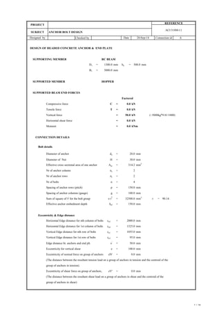
  • 1. Checked by DESIGN OF HEADED CONCRETE ANCHOR & END PLATE SUPPORTING MEMBER RC BEAM D1 = mm ha = mm B1 = mm SUPPORTED MEMBER HOPPER SUPPORTED BEAM END FORCES Factored Compressive force C = kN Tensile force T = kN Vertical force = kN (~5000kg*9.81/1000) Horizontal shear force = kN Moment = kNm CONNECTION DETAILS Bolt details Diameter of anchor do = Diameter of Nut H = Effective cross sectional area of one anchor Ase = Nr of anchor column nc = Nr of anchor rows nr = Nr of bolts n = Spacing of anchor rows (pitch) p = Spacing of anchor columns (gauge) g = Sum of square of 'r' for the bolt group e r 2 = r = Effective anchor embedment depth hef = Eccentricity & Edge distance Horizontal Edge distance for nth column of bolts ca2 = Horizontal Edge distance for 1st column of bolts ca4 = Vertical Edge distance for nth row of bolts ca1 = Vertical Edge distance for 1st row of bolts ca3 = Edge distance bt. anchors and end plt. e' = Eccentricity for vertical shear e = Eccentricity of normal force on group of anchors eN' = (The distance between the resultant tension load on a group of anchors in tension and the centroid of the group of anchors in tension) Eccentricity of shear force on group of anchors, eV' = (The distance between the resultant shear load on a group of anchors in shear and the centroid of the group of anchors in shear) 0.0 1300.0 mm Connection id 150.0 mm 32500.0 500.0 30.0 mm 90.14 2 mm2 150.0 mm 0.0 20.0 mm 0.0 50.0 314.2 mm 2 mm 1325.0 mm 100.0 1055.0 mm 0.0 2000.0 Designed by Date 20-Sep-14 100.0 mm 2 5000.0 4 0.0 50.0 mm 0.0 mm SUBJECT mm 95.0 mm ANCHOR BOLT DESIGN PROJECT REFERENCE A ACI 318M-11 1 / 14
  • 2. Checked by Connection id Designed by Date 20-Sep-14 SUBJECT ANCHOR BOLT DESIGN PROJECT REFERENCE A ACI 318M-11 Depth supported member/fin plate Ds = mm Thickness of fin plate/ supported member wed tf = mm Distance between tension bolts to compression edge D = mm mm (ca3) Design strength reduction factor f = mm (ca1) mm mm (ca2 ) (ca4 ) Plate details Depth of end plate Dp = Width of end plate Bp = Thickness of end plate tp = Material strength & grade Grade of bolt = Tensile Strength of bolt futa = Characteristic strength of Concrete (cylinder) fc ' = Yield strength of plate fyp = 1325 12 250 250 2000 560.0 95 1055 N/mm 2 N/mm2 8.8 grade 200.0 mm 20.0 mm 250.0 mm 40.0 N/mm 2 0.75 265.0 2 / 14
  • 3. Checked by Connection id Designed by Date 20-Sep-14 SUBJECT ANCHOR BOLT DESIGN PROJECT REFERENCE A ACI 318M-11 CONNECTION CAPACITY CHECKS SUMMARY TENSION LOAD Remarks 2.5ca1>hef, Blow-out strength check is not required SHEAR LOAD INTERACTION OF TENSILE AND SHEAR LOADING Interaction for single anchor (Nua/fNn+Vua/fVn) = <= 1.2 SAFE Interaction for group of anchors (Nuag/fNng+Vuag/fVng) = <= 1.2 SAFE PLATE End plate thickness required = < tp SAFE 0.096 Concrete pryout strength of group of anchors 157.16 50.0 0.318 SAFE Concrete pryout strength of an anchor 128.58 12.50 0.097 SAFE Concrete breakout strength for group of anchors 253.80 50.00 0.197 SAFE 0.050 25.00 78.6 SAFE SAFE 0.095 SAFE Concrete breakout strength of an anchor 251.93 12.50 SAFE Steel strength for group of anchors 527.79 50.00 0.095 SAFE Steel strength of an anchor 131.95 Checks Design values Utilization Ratio Capacity(kN) Load(kN) Status Concrete side-face blowout strength of anchor Pullout strength of an anchor Concrete breakout strength of an anchor 0.08 Concrete side-face blowout strength for group of anchor Pullout strength for group of anchors Concrete breakout strength for group of anchors N.A. Steel strength for group of anchors 10.1 N.A. 263.88 0.08 N.A MAXIMUM UTILIZATION RATIO SAFE 10.10 0.16 20.2 12.50 0.58 20.20 10.10 SAFE 0.08 SAFE SAFE 0.26 SAFE 0.25 20.20 10.10 20.2 N.A Steel strength of an anchor Concrete breakout strength for group of anchors near concrete edge 260.59 131.95 SAFE 0.08 Capacity(kN) Load(kN) Status Design values Utilization Ratio Checks 263.89 64.29 131.94 0.32 15.12 20.0 SAFE 3 / 14
  • 4. Checked by Connection id Designed by Date 20-Sep-14 SUBJECT ANCHOR BOLT DESIGN PROJECT REFERENCE A ACI 318M-11 MAXIMUM FORCES IN ANCHORS Shear force Torsion due to horizontal eccentricity in shear Me = V*ev' = Shear force anchor due to moment Vh = Me*r/εr 2 = Vertical shear due to Fm FVm = Fm * cosO O = = Horizontal shear due to Fm FHm = Fm * sin O = Shear force per anchor due to vertical force Vv = 50/4 = Total Shear force per anchor Vua = Shear force for group of anchors Vuag = Tension force Bearing strength of concrete = 0.85fcfc' = Force equilibrium for the design bearing stress T+N = C Considering the moment equilibrium M = T(D-Dp/2)+C(Dp-X/2) 0.85fc'fcbpX(D-X/2)-Fy(D-Dp/2) = M 20.4*200*X(250-X/2)-0*(250-250/2) = 50* 0.1+0*0+0 2.04X^2-1020X+5000 = a = b = c = X1 = -(-1020)+(-1020^2-4*2.04*5000)^0.5/(2*2.04) = X2 = -(-1020)-(-1020^2-4*2.04*5000)^0.5/(2*2.04) = Length of compressive stress block X = mm Compression force resisted by concrete C = kN Tension force transfer to anchors T = kN (Assumed to be transfer to anchors located above the C.G. of end plate) Nos of anchors row effective in tension nrt = (2 ) / 2 = -1020 2.04 5000 0 495.05 4.95 0.0 kN.m kN 12.5 kN 56.3 4.95 20.2 20.2 1.0 12.5 kN 50.0 kN KN 0.00 KN Assuming the shear transfer to anchors as below MPa 20.4 0.00 0.0 4 / 14
  • 5. Checked by Connection id Designed by Date 20-Sep-14 SUBJECT ANCHOR BOLT DESIGN PROJECT REFERENCE A ACI 318M-11 Nos of anchors efective for tension nt = 2 * 1 = Tension force on an anchor due to bending T1 = 20.2/ 2 T1 = kN Direct tension force in each anchor T2 = = kN Total tension in each anchor, Nua = T1+T2 = kN Tension force transfer to group of anchors Nuag = = kN STEEL STRENGTH OF ANCHORS As per ACI 318-05 D5.1 Nominal strength of a single anchor in tension Nsa = Ase * futa = 314.16*560/1000 = As per ACI 318-05 D4.4 a(i) f = f Nsa = >Nua SAFE ( ) Nominal strength of group of anchors in tension Nsag = nt * Ase * futa = 2*314.16*560/1000 = f Nsag = > Nuag SAFE ( ) CONCERE BREAKOUT STRENGTH OF ANCHOR Single Anchor min(ca3,1.5hef) mm min((ca1+(nr-1)p), 1.5hef) mm min(ca2, 1.5hef) min((ca4 +(nc-1)g), 1.5hef) mm mm As per ACI 318-05 D5.2 Nominal concrte breakout strength of an Ncb = ANc/ANco * yed,N * yc,N * ycp,N* Nb anchor in tension 225 95 225 2.0 10.1 Nua*nt 20.2 0.75 175.9 0 / 4 0.0 10.1 kN 131.9 kN 10.1 351.9 kN 263.9 kN 20.2 225 CAPACITY AGAINST TENSION LOADING 5 / 14
  • 6. Checked by Connection id Designed by Date 20-Sep-14 SUBJECT ANCHOR BOLT DESIGN PROJECT REFERENCE A ACI 318M-11 Basic concrete breakout strength of an anchor Nb = kc sqrt(fc ' ) hef 1.5 in cracked concrete For cast-in anchors kc = Actual anchor embedment depth h1 = ca,min = mm ca,max = mm Max(Cmax/1.5,max spacing/3) h2 = mm Effective anchor embedment depth hef = If 1.5*h1>Cmax = h2 or h1 = Nb = 10* sqrt(40) *150^1.5 Nb = Modification factor for edge effects yed,N = 0.7 + 0.3 (ca,min/1.5hef) for ca,min <1.5hef = for ca,min >1.5hef yed,N = Modification factor to account for cracking yc,N = Modification factor to account for post-install ycp,N = For cast-in anchors anchors Projected concerte failure area of an anchor ANco = 9 hef 2 (not limited by edge distance or spacing) = 9 *150^2 = Projected concerte failure area of an anchor = (225+95) * (225+225) < ANco ( limited by edge distance or spacing) = ANc = Nominal concrte breakout strength of an Ncb = (144000/202500) * 0.83*1.25*1*116.19 anchor in tension = f Ncb = >Nua SAFE ( ) Group of anchors Basic concrete breakout strength of an anchor Nb = kc sqrt(fc ' ) hef 1.5 in cracked concrete For cast-in anchors kc = Actual anchor embedment depth h1 = ca,min = mm ca,max = mm Max(Cmax/1.5,max spacing/3) h2 Effective anchor embedment depth hef = If 1.5*h1>Cmax = h2 or h1 = Nb = 10* sqrt(40) *150^1.5 = 116.2 10.0 150.0 mm 150.0 mm 95 225 0.83 1.25 1.00 202500.0 mm2 116.2 kN 1.0 10.1 144000.0 mm2 144000.0 mm 2 85.7 kN kN 150 mm 150.0 mm 64.3 kN 150.0 mm 150 95 225 10.0 6 / 14
  • 7. Checked by Connection id Designed by Date 20-Sep-14 SUBJECT ANCHOR BOLT DESIGN PROJECT REFERENCE A ACI 318M-11 min(ca3, 1.5hef) mm (nrt-1)p = mm min((ca1+(nr-1)p-(nrt-1)p), 1.5hef) mm min(ca2, 1.5hef) (nc-1)g min(ca4, 1.5hef) mm mm mm Modification factor for eccentrically loaded anchor group yec,N = 1/(1 + (2e'N / 3hef)) Modification factor for edge effects = 0.7 + 0.3 (ca,min/1.5hef) for ca,min <1.5hef = for ca,min >1.5hef yed,N = Modification factor to account for cracking yc,N = Modification factor to account for post-install ycp,N = For cast-in anchors anchors Projected concerte failure area of an anchor ANco = 9 hef 2 (Not limited by edge distance or spacing) = 9 *150^2 = Projected concerte failure area of group of = (95+0+225) * (225+100+225) (Limited by edge distance or spacing) = < nt ANco ANc = ( mm 2 ) Nominal concrte breakout strength for Ncbg = ANc/Anco yec,N* yed,N * yc,N * ycp,N* Nb group of anchors in tension = (176000/202500) * 1*0.83*1.25*1* 116.19 = f Ncbg = > Nuag SAFE ( ) PULLOUT STRENGTH OF ANCHOR As per ACI 318-05 D5.3 Nominal pullout strength of an anchor Npn = yc,P * Np in tension Pullout strength in tension of an Np = Abrg * 8* fc ' headed bolt or headed bolt 225 100 225 95 225 1.00 1.0 78.6 kN 0.83 1.25 1.00 202500.0 mm 2 176000.0 mm2 20.2 176000.0 mm2 405000 104.8 kN 0 7 / 14
  • 8. Checked by Connection id Designed by Date 20-Sep-14 SUBJECT ANCHOR BOLT DESIGN PROJECT REFERENCE A ACI 318M-11 Bearing area of the head of bolt or anchor Abrg = pi() * (30^2 - 20^2 )/ 4 bolt = Pullout strength in tension of an Np = 392.7 * 8 * 40 headed bolt or headed bolt = Modification factor to account for cracking yc,P = Single Anchor Nominal pullout strength of an anchor Npn = 1.4* 125.66 = f Npn = >Nua SAFE ( ) Group of anchors Nominal pullout strength of group of anchor Npng = 2 * 175.92 = f Npng = > Nuag SAFE ( ) CONCRETE SIDE-FACE BLOWOUT STRENGTH OF ANCHOR Single anchor As per ACI 318-05 D5.4 Nominal side-face blowout strength of an anchor Nsb = 13 ca1 sqrt(Abrg) sqrt(fc') ca1 = mm Abrg = Perpendicular distance to ca1 ca2 = mm If ca2 < 3ca1, Nsb shall be multiplied by a factor (1+ca2/ca1)/4 (1+ca2/ca1)/4 = Nominal side-face blowout strength of an anchor Nsb = 13 * 95 * sqrt(392.7) * sqrt(40)*1 = Nominal side-face blowout strength of an anchor Nsb = anchor in tension f Nsb = >Nua SAFE ( ) 2.5ca1>hef, Blow-out strength check is not required 392.70 mm2 125.66 kN 1.40 175.92 kN 131.9 kN 10.1 351.8 kN 263.9 kN 20.2 95 1.0 392.70 392.70 mm2 1325.0 154.8 kN N.A. kN N.A. kN 10.1 8 / 14
  • 9. Checked by Connection id Designed by Date 20-Sep-14 SUBJECT ANCHOR BOLT DESIGN PROJECT REFERENCE A ACI 318M-11 Group of anchors For multiplie headed anchors Nsbg = (1+s/6ca1) Nsb Spacing of outer anchors along the edge s = Nominal side-face blowout strength of Nsbg = (1+100/(6*95))*154.78 group of anchors in tension Nominal side-face blowout strength of Nsbg = group of anchors in tension 2.5ca1>hef, Blow-out strength check is not required f Nsbg = > Nuag SAFE ( ) STEEL STRENGTH OF ANCHOR As per ACI 318-05 D 6.1 Nominal strength of an anchor in shear Vsa = Ase * futa = 314.16*560/100 = f Vsa = > Vua SAFE ( ) Nominal strength of anchor group in shear Vsag = n * Ase * futa 4*314.16*560/1000 = f Vsag = > Vuag SAFE ( ) Nominal strength of anchor group f Vsag = f* nc * Ase * futa in shear (for no. of columns of anchors) = BREAKOUT STRENGTH OF ANCHOR Single anchor As per ACI 318-05 D 6.2 Nominal breakout strength of an anchor for shear force perpendicular to the edge Vcb = AVc/AVco * yed,V * yc,V * Vb Basic concrete breakout strength of an anchor Vb = 0.6 (le/da) 0.2 sqrt(da)sqrt(fc ' ) ca1 1.5 in cracked concrete le = min.( hef, 8da) = Actual edge distance ca1 = 100.0 mm 175.9 kN 131.9 kN 181.9 kN N.A. kN N.A. kN 12.5 703.7 kN 527.8 kN 50.0 263.9 kN 150.0 mm 1055.0 mm CAPACITY AGAINST VERTICAL SHEAR LOADING 20.2 9 / 14
  • 10. Checked by Connection id Designed by Date 20-Sep-14 SUBJECT ANCHOR BOLT DESIGN PROJECT REFERENCE A ACI 318M-11 min(ha, 1.5ca1) mm min(ca2, 1.5ca1) min((nc-1)g+ca4, 1.5ca1) mm mm ca2max = mm ca2min = mm ha = s = mm Minimum free edge distance ef = Min(ha,ca2min) = Effective anchor edge distance ca1 = if ef< 1.5ca1= max(ca2/1.5,ha/1.5,S/3 or Ca1) = Vb = 0.6 * (150/20)^0.2 * sqrt(20) * sqrt(40) * 1055^1.5 Vb = Modification factor for edge effects yed,V = 0.7 + 0.3 (ca2/1.5ca1) for ca2 <1.5ca1 = for ca2 >1.5ca1 yed,V = Modification factor to account for cracking yc,V = Projected concrete failure area of an anchor AVco = 4.5 ca1 2 (Not limited by corner influence, spacing, or member thickness) = 4.5 *1055 ^ 2 AVco = Projected concrete failure area of an anchor = (1325 + 1582.5) * 500 (Limited by corner influence, spacing, or member thickness) = < Avc0 AVc = Nominal concrete breakout strength of an Vcb = (1453750/5008612.5) * 0.95*1.4*870.14 anchor for shear force = f Vcb = > Vua SAFE ( ) 2000 1325 500 1582.5 500.0 mm 100.0 870.1 kN 1055.0 mm 1325.0 500.0 mm mm2 mm 2 5008612.5 1453750.0 1.0 0.95 1.40 mm 2 335.9 kN 251.9 kN 1453750.0 12.5 10 / 14
  • 11. Checked by Connection id Designed by Date 20-Sep-14 SUBJECT ANCHOR BOLT DESIGN PROJECT REFERENCE A ACI 318M-11 Group of anchors min(ha, 1.5ca1) mm min(ca2, 1.5ca1) (nc-1)g min(ca4, 1.5ca1) mm mm mm Basic concrete breakout strength of an anchor Vb = 0.6 (le/do) 0.2 sqrt(d0)sqrt(fc ' ) ca1 1.5 in cracked concrete Where, le = min.( hef, 8d0) = Actual edge distance ca1 = ca2max = ca2min = ha = s = Minimum free edge distance ef = Min(ha,ca2min) = Effective anchor edge distance ca1 = if ef< 1.5ca1= max(ca2/1.5,ha/1.5,S/3 or Ca1) = Vb = 0.6 * (150/20)^0.2 * sqrt(20) * sqrt(40) * 1055^1.5 Vb = Modification factor for eccentrically loaded yec,V = 1/(1 + (2e'V / 3ca1)) anchor group = Modification factor for edge effects yed,V = 0.7 + 0.3 (ca2/1.5ca1) for ca2 <1.5ca1 = for ca2 >1.5ca1 yed,V = ca2,min = mm Modification factor to account for cracking yc,V = Projected concrete failure area of an anchor, AVco = 4.5 ca1 2 (Not limited by corner influence, spacing, or member thickness) = 4.5 *1055 ^ 2 AVco = Projected concrete failure area for groups of AVc = (1325 + 100+ 1582.5) * 500 < nc AVc (Limited by corner influence, spacing, or member thickness) = = mm 2 AVc = 2000 1582.5 500 1325 100 150.0 mm mm 2 1055.0 mm 500.0 mm 870.1 0.95 1.40 1055.0 mm mm 1325 mm 500.0 mm mm2 1503750.0 5008612.5 kN 1.0 1.0 mm 2 10017225 1503750.0 150.0 mm 11 / 14
  • 12. Checked by Connection id Designed by Date 20-Sep-14 SUBJECT ANCHOR BOLT DESIGN PROJECT REFERENCE A ACI 318M-11 Nominal concrete breakout strength for Vcbg = AVc/AVco * yec,V* yed,V * yc,V * Vb group of anchors in a single row for shear force = (1503750/5008612.5) * 1*0.95*1.4* 870.14 = f Vcbg = > nc*Vua SAFE ( ) Group of anchors min(ha, 1.5ca1) mm min(ca2, 1.5ca1) (nc-1)g min(ca4, 1.5ca1) mm mm mm Basic concrete breakout strength of an anchor Vb = 0.6 (le/do)0.2 sqrt(d0)sqrt(fc ' ) ca1 1.5 in cracked concrete Where, le = min.( hef, 8d0) = Actual edge distance ca1 = ca2max = ca2min = ha s Effective anchor edge distance ca1 = if ef< 1.5ca1= max(ca2/1.5,ha/1.5,S/3 or Ca1) = Vb = 0.6 * (150/20)^0.2 * sqrt(20) * sqrt(40) * 1205^1.5 Vb = Modification factor for eccentrically loaded yec,V = 1/(1 + (2e'V / 3ca1)) anchor group = Modification factor for edge effects yed,V = 0.7 + 0.3 (ca2/1.5ca1) for ca2 <1.5ca1 = for ca2 >1.5ca1 yed,V = Modification factor to account for cracking yc,V = 1807.5 100 1325 mm 500 347.5 kN 150.0 mm 500.0 260.6 kN 25.0 2000 mm 150.0 kN 1205.0 mm 1.00 1.0 1205.0 mm 1.40 0.92 1325 mm mm 1062.2 12 / 14
  • 13. Checked by Connection id Designed by Date 20-Sep-14 SUBJECT ANCHOR BOLT DESIGN PROJECT REFERENCE A ACI 318M-11 Projected concrete failure area of an anchor, AVco = 4.5 ca1 2 (Not limited by corner influence, spacing, or member thickness) = 4.5 *1205 ^ 2 AVco = Projected concrete failure area for groups of = (1325 + 100+ 1807.5) * 500 < n Avco (Limited by corner influence, spacing, or member thickness) = = mm 2 AVc = Nominal concrete breakout strength for Vcbg = AVc/AVco * yec,V* yed,V * yc,V * Vb group of anchors for shear force = (1616250/6534112.5) * 1*0.92*1.4* 1062.16 = f Vcbg = > Vuag SAFE ( ) CONRETE PRYOUT STRENGTH OF ANCHOR Single anchor As per ACI 318-05 D 6.3 Nominal pryout strength of an anchor Vcp = kcp * Ncb kcp = Nominal concrte breakout strength of an anchor Ncb = Nominal pryout strength of an anchor Vcp = 2* 85.72 = f Vcp = > Vua SAFE ( ) Group of anchors Nominal concrte breakout strength for Ncbg = Nominal pryout strength for group of anchor Vcpg = kcp * Ncbg = 2* 104.77 = f Vcpg = > Vuag SAFE ( ) INTERACTION OF TENSILE AND SHEAR FORCES Lowest design strength in tension f Nn = min. ( 131.95, 64.29, 131.94, N.A. ) of an anchor = > Nua SAFE ( ) 338.4 kN 253.80 kN mm 2 mm2 6534112.5 12.5 104.8 kN 50.0 2.0 85.7 kN 209.5 kN 157.2 kN 50.0 171.4 kN 128.6 kN 64.3 kN 10.1 26136450 1616250.0 1616250.0 mm 2 13 / 14
  • 14. Checked by Connection id Designed by Date 20-Sep-14 SUBJECT ANCHOR BOLT DESIGN PROJECT REFERENCE A ACI 318M-11 Lowest design strength in tension f Nng = min. ( 263.89, 78.58, 263.88, N.A. ) of group of anchors = > Nuag SAFE ( ) Lowest design strength in shear f Vn = min. ( 131.95, 251.93, 128.58 ) of an anchor = > Vua SAFE ( ) Lowest design strength in shear f Vng = min. ( 527.79, 253.8, 157.16 ) of group of anchors = > Vuag SAFE ( ) Inetraction check for single anchor Nua Vua = (10.1 / 64.29) + (12.5/ 128.58) f Nn f Vn = <= 1.2 SAFE Inetraction check for group of anchors Nuag Vuag = ((20.2 / 78.58) + (50/ 157.16) f Nng f Vng = <= 1.2 SAFE END PLATE THICKNESS Edge distance = mm Number of bolts in tension side nf = Tension in group of anchors T1 = Nua*nf = kN Moment on plate due to tension Mt = T1*ev = kNm Thickness of end plate required = SQRT(6*M2/(Bp*fyp)) = SQRT((6*2.02*10^6/(200*265)) = mm > SAFE ( ) 20.2 12.5 50.0 100 78.6 kN 128.6 kN 157.2 kN + + 0.58 tp 20.2 0.25 20.0 2.02 15.12 treq2 2 14 / 14