
Recommended
More Related Content
What's hot
What's hot (20)
Similar to Basement wall design
Similar to Basement wall design (20)
Recently uploaded
Recently uploaded (20)
Basement wall design
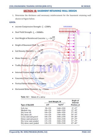
- 1. CIVIL ENGINEERING TRAINING CENTER (BIM-CETC) RC DESIGN Prepared By: Mr. SENG PHEARAK (M.ENG, S.E) PAGE: 243 SECTION 18: BASEMENT RETAINING WALL DESIGN 1. Determine the thickness and necessary reinforcement for the basement retaining wall shown in Figure below. GIVEN: • oncrete Compressive Strength: ' cf 25MPa= • Steel Yield Strength: yf 390MPa= • Unit Weight of Reinforced Concrete: c 3 kN 24 m = • Height of Basement Wall: wh 3m= • Soil Density (Backfill): s 3 kN 18 m = • Water Density: w 3 kN 10 m = • Traffic/Parking Load Surcharge: s 2 kN w 2.4 m = • Internal Friction Angle of Soil: 30 = • Concrete/Clear Cover: cv 40mm= • Vertical Rebar Diameter: s 12mm = • Horizontal Rebar Diameter: h 12mm = A B Ha Ps hw/2 SURCHARGE Hs hw/3 Pa hw
- 2. CIVIL ENGINEERING TRAINING CENTER (BIM-CETC) RC DESIGN Prepared By: Mr. SENG PHEARAK (M.ENG, S.E) PAGE: 244 SOLUTION ❖ Step 1: Given Data • Concrete compressive strength: ' cf 25MPa= • Steel Yield Strength: yf 390MPa= • Unit Weight of Reinforced Concrete: c 3 kN 24 m = • Height of Basement Wall: wh 3m= • Soil Density (Backfill): s 3 kN 18 m = • Water Density: w 3 kN 10 m = • Traffic/Parking Load Surcharge: s 2 kN w 2.4 m = • Internal Friction Angle of Soil: 30 = • Concrete/Clear Cover: cv 40mm= ❖ Step 2: Determine The Thickness of the Wall • Thickness of Wall: w w h 3000mm t max ,100mm max ,190mm 190mm 200mm 25 25 = = = =
- 3. CIVIL ENGINEERING TRAINING CENTER (BIM-CETC) RC DESIGN Prepared By: Mr. SENG PHEARAK (M.ENG, S.E) PAGE: 245 ❖ Step 3: Load on Basement Wall • Earth Pressure & Concentrated Load: a a soil w a a 3 P C h b 1 Sin 1 Sin30 C 0.333333 1 Sin 1 Sin30 kN kN P 0.3333 18 3m 1m 18 mm = − − = = = + + = = a w a kN 18 3mP h mH 27kN 2 2 = = = • Water Pressure & Concentrated Load (In Case Soil is wet: 50%): w w w w 3 w w w P 50% h b kN kN P 50% 10 3m 1m 15 mm kN 15 3mP h mH 22.5kN 2 2 = = = = = = • Effect of Surcharge Load & Concentrated Load: 2 s s s 3 s a s s 3 s s w kN 2.4 w mh 0.13333m kN 18 m kN kN P C h b 0.333333 18 0.133333m 1m 0.8 mm kN H P h 0.8 3m 2.4kN m = = = = = = = = = A A B B A B RA RB M u.positive M u.negative Pw Hw Pa Ha Ps hw Hs B A x
- 4. CIVIL ENGINEERING TRAINING CENTER (BIM-CETC) RC DESIGN Prepared By: Mr. SENG PHEARAK (M.ENG, S.E) PAGE: 246 ❖ Step 4: Calculate Bending Moment & Shear Force ( ) ( ) w w u.neg a w s u.neg h h M 1.6 H H 1.6H 7.5 8 3m 3m M 1.6 27kN 22.5kN 1.6 2.4kN 33.12kN.m 7.5 8 = + + = + + = ( ) ( ) ( ) ( ) ( ) ( ) a w w s w u.neg B w B A a w s B u A B H H h H h 1.6 M 3 2 R h 27kN 22.5kN 3m 2.4kN 3m 1.6 33.12kN.m 3 2 R 17.28kN 3m R 1.6 H H H R 1.6 27kN 22.5kN 2.4kN 17.28kN 65.76kN V max R ,R max 17.28kN,65.76kN 65.76kN + + − = + + − = = = + + − = + + − = = = = ( ) ( ) ( ) ( ) 2a w s B w 2 3 2s a w u.pos B w 2 u.pos P P 1.6 x 1.6P x R 0 2h 18kN / m 15kN / m 1.6 x 1.6 0.8kN / m x 17.28kN 0 2 3m x 1.33045m P P P x M R x 1.6 x 1.6 2 2h 3 0.8kN / m 17.18kN 1.33045m 1.6 1.33045m 2 M 18kN / m 15k 1.6 + + − = + + − = = + = − − + + − + = − + + ( )3 14.94kN.m 1.33045mN / m 2 3m 3 =
- 5. CIVIL ENGINEERING TRAINING CENTER (BIM-CETC) RC DESIGN Prepared By: Mr. SENG PHEARAK (M.ENG, S.E) PAGE: 247 ➢ Using CSI Etabs 2018, we get the results as following Bending Moment Diagram Shear Force Diagram ➢ Using Robot Structural Analysis Professional 2020, we get the results as following Surcharge Load: (Ps) Water Pressure: (Pw) Soil Pressure(Backfill): (Pa)
- 6. CIVIL ENGINEERING TRAINING CENTER (BIM-CETC) RC DESIGN Prepared By: Mr. SENG PHEARAK (M.ENG, S.E) PAGE: 248 Bending Moment Diagram Shear Force Diagram
- 7. CIVIL ENGINEERING TRAINING CENTER (BIM-CETC) RC DESIGN Prepared By: Mr. SENG PHEARAK (M.ENG, S.E) PAGE: 249 ❖ Step 5: Calculate Required Reinforcement ➢ Case: Negative Bending Moment u.negM 33.12kNm= • Calculate b max min, , , ( )' 1 c ' c b 1 y y y 5 s max b 0.85 17MPa f 25MPa 28MPa f 600 25MPa 600MPa 0.85 0.85 0.85 0.028 f 600 f 390MPa 600MPa 390MPa f 3900.003 0.003 E 2 10 0.028 0. 0.008 0.008 = = = = = + + + + = = = ( )min s y 2 v.min min w 0174 0.0015 10mm 16mm and f 390MPa 420MPa A bt 0.0015 1000mm 200mm 300mm = = = = = = ( ) s 6 u.neg u 2 2 ' c u ' y c 12mm d h cv 200mm 40mm 154mm 2 2 M 33.12 10 Nmm R 1.3965MPa bd 1000mm 154mm f 2R 25MPa 2 1.3965MPa 0.85 1 1 0.85 1 1 0.0041355 f 390MPa 0.85 25MPa 0.90.85f 0.0041 = − − = − − = = = = = − − = − − = = ( ) ( ) max 2 s 2 2 2 s.use s v.min 355 0.0174 A bd 0.0041355 1000mm 154mm 636.867mm A max A ,A max 636.867mm ,300mm 636.867mm = = = = = = =
- 8. CIVIL ENGINEERING TRAINING CENTER (BIM-CETC) RC DESIGN Prepared By: Mr. SENG PHEARAK (M.ENG, S.E) PAGE: 250 ( ) ( ) ( ) ( ) 2 s s 2 s1 s max w use max A 636.867mm n 5.631 6 A 12mm 4 b 1000mm s 166.66mm 160mm n 6 s min 3t ,450mm min 3 200mm,450mm 450mm s min s,s 160mm = = = = = = = = = = = = ➢ Case: Positive Bending Moment u.posM 14.94kN.m= • Calculate b max min, , , ( ) max min s y 2 v.min min w 0.0174 0.0015 10mm 16mm and f 390MPa 420MPa A bt 0.0015 1000mm 200mm 300mm = = = = = = = ( ) s 6 u.neg u 2 2 ' c u ' y c 12mm d h cv 200mm 20mm 174mm 2 2 M 14.94 10 Nmm R 0.4934MPa bd 1000mm 174mm f 2R 25MPa 2 0.4934MPa 0.85 1 1 0.85 1 1 0.0014243 f 390MPa 0.85 25MPa 0.90.85f = − − = − − = = = = = − − = − − = ( ) ( ) ( ) ( ) max 2 s 2 2 2 s.use s v.min 2 s.use s 2 s1 s max w 0.0014243 0.0174 A bd 0.0014243 1000mm 174mm 247.83mm A max A ,A max 247.83mm ,300mm 300mm A 300mm n 2.6525 3 A 12mm 4 b 1000mm s 333.33mm 330mm n 3 s min 3t ,450mm min 3 200mm, = = = = = = = = = = = = = = = = = ( ) ( )use max 450mm 450mm s min s,s 330mm = = =
- 9. CIVIL ENGINEERING TRAINING CENTER (BIM-CETC) RC DESIGN Prepared By: Mr. SENG PHEARAK (M.ENG, S.E) PAGE: 251 ❖ Step6: Determine Shear Force & Check Shear Capacity (Section Adequacy) • Shear Force uV 65.76kN= • Check Shear Capacity ' 3 c c c u 1 1 V f bd 0.75 1 25MPa 1000mm 155mm 10 96.875kN 6 6 V 96.875kN V 65.76kN (OK) − = = = = = Wall Thickness is Sufficient to Resist Shear Force. Shear Reinforcement is not required. ❖ Step7: Determine the Minimum Distributed Horizontal Reinforcement ( ) ( ) ( ) ( ) ( ) min s y 2 h.min min w 2 h.min s 2 s1 s max w use max 0.0025 10mm 16mm and f 390MPa 420MPa A bt 0.0025 1000mm 200mm 500mm A 500mm n 4.42 5 A 10mm 4 b 1000mm s 200mm n 5 s min 3t ,450mm min 3 200mm,450mm 450mm s min s,s 200mm = = = = = = = = = = = = = = = = =
- 10. CIVIL ENGINEERING TRAINING CENTER (BIM-CETC) RC DESIGN Prepared By: Mr. SENG PHEARAK (M.ENG, S.E) PAGE: 252 Summary Result Direction Location Bending Moment Diameter of Rebar Spacing of Rebar Vertical Exterior Face u.negM 33.12kNm= 12mm 160mm Interior Face u.posM 14.94kN.m= 12mm 330mm Horizontal Both Side - 12mm 200mm 1000 DB12@160 BASEMENT WALL REINFORCEMENT DETAIL SCALE: 1/50 3000 DB12@200 DB12@160 DB12@330