Systems and methods for visual presentation and selection of ivr menu
•
0 likes•25 views

Embodiments of the invention provide a system for generating an Interactive Voice Response (IVR) database, the system comprising a processor and a memory coupled to the processor. The memory comprising a list of telephone numbers associated with one or more destinations implementing IVR menus, wherein the one or more destinations are grouped based on a plurality of categories of the IVR menus. Further the memory includes instructions executable by said processor for automatically communicating with the one of more destinations, and receiving at least one customization record from said at least one destination to store in the IVR database.

Recommended
Recommended
More Related Content
Similar to Systems and methods for visual presentation and selection of ivr menu
Similar to Systems and methods for visual presentation and selection of ivr menu (20)
More from Tal Lavian Ph.D.
More from Tal Lavian Ph.D. (20)
Recently uploaded
Recently uploaded (20)
Systems and methods for visual presentation and selection of ivr menu
- 1. (19) United States US 20150010136A1 (12) Patent Application Publication (10) Pub. No.: US2015/0010136A1 Lavian et al. (43) Pub. Date: Jan. 8, 2015 (54) SYSTEMS AND METHODS FORVISUAL (52) U.S. Cl. PRESENTATION AND SELECTION OF VR CPC ..................................... H04M 3/493 (2013.01) MENU USPC ....................................................... 379/88.11 (71) Applicants:Tal Lavian, Sunnyvale, CA (US); Zvi (57) ABSTRACT Or-Bach, San Jose, CA (US) Embodiments ofthe invention provide a system for generat (72) Inventors: Tal Lavian, Sunnyvale, CA (US); Zvi ingan InteractiveVoice Response(IVR) database, thesystem Or-Bach, San Jose, CA (US) comprisingaprocessoranda memory coupledto the proces sor. The memory comprising a list of telephone numbers (21) Appl. No.: 13/934,248 associated with one or more destinations implementing IVR menus, wherein the one or more destinations are groupedgroup (22) Filed: Jul. 3, 2013 based on a plurality ofcategories ofthe IVR menus. Further O O the memory includes instructions executable by said proces Publication Classification sor for automatically communicating with the one of more (51) Int. Cl destinations, and receiving at least one customization record itouMsA93 (2006.01) from saidatleast one destinationto storeinthe IVRdatabase. 1083 Destination 108b. Destination Device (Telephone) Cater 108C Destination 106 104. O2a O O
- 2. US 201S/0010136A1Jan. 8, 2015 Sheet 1 of92PatentApplication Publication
- 3. US 201S/0010136A1Jan. 8, 2015 Sheet 2 of92PatentApplication Publication CIZO!
- 4. US 201S/0010136A1Jan. 8, 2015 Sheet 3 of92PatentApplication Publication ----^-} ???. 90|| |-
- 5. US 201S/0010136A1Jan. 8, 2015 Sheet 4 of92PatentApplication Publication
- 6. US 201S/0010136A1Jan. 8, 2015 Sheet 5 of92 £80|| PatentApplication Publication Kewe?eg)
- 7. US 201S/0010136A1Jan. 8, 2015 Sheet 6 of92PatentApplication Publication
- 8. US 201S/0010136A1Jan. 8, 2015 Sheet 7 of92PatentApplication Publication
- 9. US 201S/0010136A1Jan. 8, 2015 Sheet 8 of92PatentApplication Publication @@@ÁJOudeW eZO!
- 10. US 201S/0010136A1Jan. 8, 2015 Sheet 9 of92PatentApplication Publication 909
- 11. US 201S/0010136A1Jan. 8, 2015 Sheet 10 of92PatentApplication Publication ;------------------------------------------------------------------------------------||||rozol
- 12. US 201S/0010136A1Jan. 8, 2015 Sheet 11 of92PatentApplication Publication
- 13. Patent Application Publication Jan. 8, 2015 Sheet 12 of92 US 201S/0010136A1 > C Y is C. e. 59G 9 Š Z s
- 15. Patent Application Publication Jan. 8, 2015 Sheet 14 of92 US 201S/0010136A1 CO CO vs. CN O O O O CO CO CO CO f 9wer (s S2 S. O. Ce CD Cwed O E CD Ca c 9) CO CfO s SO) . 2 S CDser O l s C. O s
- 16. US 201S/0010136A1Jan. 8, 2015 Sheet 15 of92PatentApplication Publication
- 17. US 201S/0010136A1Jan. 8, 2015 Sheet 16 of92PatentApplication Publication Je?nduOOg
- 18. US 201S/0010136A1Jan. 8, 2015 Sheet 17 of92PatentApplication Publication C90, O OleMO
- 19. Patent Application Publication Jan. 8, 2015 Sheet 18 of92 US 201S/0010136A1
- 20. Patent Application Publication Jan. 8, 2015 Sheet 19 of92 US 201S/0010136A1
- 21. US 201S/0010136A1Jan. 8, 2015 Sheet 20 of92PatentApplication Publication
- 22. Patent Application Publication Jan. 8, 2015 Sheet 21 of92 US 201S/0010136A1 1502 Detect phone number of a destination dialed from a device 1504 Search for IVR information in visual menu database on the device is a visual menu for destination available in Visual menu database? N.G.) Yes 1508 Display the visual menu and associated information 1510 Detect input from caller on the visual menu 1512 Connect to the destination based on inputs from the Caler 1514 is the visual NO menu Correct? 1516 Yes Maintain the Connection ti Caier or destination disconnects FIG. 15A
- 23. Patent Application Publication Jan. 8, 2015 Sheet 22 of92 US 201S/0010136A1 1518 Connect the device to a remote repository 1520 N.Go)is the visual menu available in emote repository? Yes 1522 N Update the visual menu database from remote repository is the visual menu available in updated visual menu database? No 1526 Updatethe remote repository (E) FIG. 15B
- 24. Patent Application Publication Jan. 8, 2015 Sheet 23 of92 US 201S/0010136A1 1528 Any menu selection detected On the device? 1530 Provide the diated number as a destination to remote repository FIG. 15C
- 25. Patent Application Publication Jan. 8, 2015 Sheet 24 of92 US 201S/0010136A1 1558 Connect device to a remote repository 1560 ls there an updated version of the visual menu in the remote repository? FIG. 15D
- 26. US 201S/0010136A1Jan. 8, 2015 Sheet 25 of92PatentApplication Publication
- 27. US 201S/0010136A1Jan. 8, 2015 Sheet 26 of92PatentApplication Publication
- 28. US 201S/0010136A1Jan. 8, 2015 Sheet 27 of92 quæ6/uol?onu?SuOO?seqe?eG PatentApplication Publication
- 29. US 201S/0010136A1Jan. 8, 2015 Sheet 28 of92PatentApplication Publication Repository Connection Module
- 30. Patent Application Publication Jan. 8, 2015 Sheet 29 of92 US 201S/0010136A1 1802 - Connect to a destination 1804 Analyze a first level ofthe audible IVR ent 1806 - Store the information regarding the audible IVR menu in a database NO Are there any sub menus in the audible VR menu? Yes 1810 N. Analyze the sub-menus Store the information regarding the Sub-menus in the database Are there any Sub menuS in the Sub menus? 1812 NO FIG. 18
- 31. US 201S/0010136A1Jan. 8, 2015 Sheet 30 of92PatentApplication Publication 806j.
- 32. Patent Application Publication Jan. 8, 2015 Sheet 31 of92 US 201S/0010136A1 Record Database Content 2002 Please enter invoice number 2004a Please enterthe payment amount 2006a Please choose yourpayment card: 2008a Press 1 for VISA or 2 for MasterCard Please enter your Credit Card 2012a expiry date Please say or enter your 2010a Credit Card number FIG20A
- 33. Patent Application Publication Jan. 8, 2015 Sheet 32 of92 US 201S/0010136A1 Payment Form for ABC 2014 Please choose your payment card: O) VISA O MasterCard FIG.2OB
- 35. US 201S/0010136A1Jan. 8, 2015 Sheet 34 of92PatentApplication Publication |S pueOg
- 36. Patent Application Publication Jan. 8, 2015 Sheet 35 of92 US 201S/0010136A1 2302 ldentify phone number of a destination dialed from a device 2304 Determine a location COde aSSOciated with Current OCation of the device 2306 Determine a business category associated with dialed y phone number Search for destination phone numbers matching the 2308 business category of the dialed phone number stored on a database 2310 Are One Or more destination phone numbers available? NOGA) Yes 2312 Search foratleastone destination phone number from the destination phone numbers based on location code FIG. 23A
- 37. Patent Application Publication Jan. 8, 2015 Sheet 36 of92 US 201S/0010136A1 2328 Request updates from a server 2330 N. Receive updates from the server Store updates in the database On the device 2332 FIG. 23B
- 38. Patent Application Publication Jan. 8, 2015 Sheet 37 of92 US 201S/0010136A1 2314 ls at east one destination phone number available 2 NO 2326 Display a visual VR Yes menu of the diated destination phone number 2316 Display the at east one destination phone number and associated properties 2318 Select a destination phone number, 2320 Display a visual IVR menu of the Selected destination 2322 Select an option from the visual VR e 2324 Connect to the selected option ofthe destination Stop FIG. 23C
- 39. Patent Application Publication Jan. 8, 2015 Sheet 38 of92 US 201S/0010136A1 2402 N identify a numberofdestination dialed by a callerofthe device 2404 Search for an advertisement associated with the number in a database 2406 - Display the advertisement on the device is a selection of Yes advertisement bythe caller detected? FIG. 24.
- 40. US 201S/0010136A1Jan. 8, 2015 Sheet 39 of92PatentApplication Publication puo^^Ssedu??ueeseel)
- 41. US 201S/0010136A1Jan. 8, 2015 Sheet 40 of92PatentApplication Publication 0|92
- 42. Patent Application Publication Jan. 8, 2015 Sheet 41 of92 US 201S/0010136A1 26O2 Dial a phone number ofa destination 2604 Display a visual VR menu corresponding to the dialed number On Caier device 2606 Select an option from the displayed visual VR menu 2608 - Display a form indicatingthe information required bythe IVR of the destination 2610 - Fiil the information in the displayed form 2612 N Establish a connection between the destination and the Caler device Stop FIG. 26
- 43. US 201S/0010136A1Jan. 8, 2015 Sheet 42 of92 JequuntupueOg PatentApplication Publication ZO
- 44. US 201S/0010136A1Jan. 8, 2015 Sheet 43 of92 808Z ?, Jequunu PatentApplication Publication
- 46. Patent Application Publication Jan. 8, 2015 Sheet 45 of92 US 201S/0010136A1 3002 Dial a phone number ofa destination from a device 3OO4. Display a scheduling mode option and a visual interactive Voice Response (IVR) menu associated with the dialed destination 3OO6 Switch the device to a scheduling mode 3008 Save a selection information including one or more options of the visual IVR menu 3010 N Save a call schedule including a dateand time information Has the date and time for the Cat schedule arrived? Wait for the Cal Schedule's date Yes and time FIG. 3OA
- 47. Patent Application Publication Jan. 8, 2015 Sheet 46 of92 US 201S/0010136A1 (a) 3016 On the Selection information 3020 3022 3024 FIG. 3OB
- 48. US 201S/0010136A1Jan. 8, 2015 Sheet 47 of92PatentApplication Publication €804,9 0||||8 00||9
- 49. US 201S/0010136A1Jan. 8, 2015 Sheet 48 of92PatentApplication Publication 0$$$ 00||$ €ZO19 90||9
- 50. US 201S/0010136A1Jan. 8, 2015 Sheet 49 of92PatentApplication Publication C#70||9 0||||9 |- 00||8 90#9
- 51. US 201S/0010136A1 0||||9 90||9 Jan. 8, 2015 Sheet 50 of92 |- PatentApplication Publication
- 52. US 201S/0010136A1Jan. 8, 2015 Sheet 51 of92PatentApplication Publication ZOZ$
- 53. US 201S/0010136A1Jan. 8, 2015 Sheet 52 of92PatentApplication Publication
- 54. Patent Application Publication Jan. 8, 2015 Sheet 53 of92 US 201S/0010136A1 34O2 a Search, at a first communication device, for a data network is data network available? 34O6 Send a first section ofa packet to the Second Communication device as Dual-TOne Multi frequency signals 34.08 Send a first section ofthe packet comprising first information to the Second Communication device Yes ls Visuphone available at Second Communication device? No->GB) Yes FIG. 34A
- 55. Patent Application Publication Jan. 8, 2015 Sheet 54 of92 US 201S/0010136A1 Receive an acknowledgement message based On the first section from the Second Communication device 3412 Send a second section ofthe packet comprising second information based on the acknowledgement messageto the second Communication device 3414 FIG. 34B
- 56. US 201S/0010136A1Jan. 8, 2015 Sheet 55 of92PatentApplication Publication 909€. 0099 98099
- 57. US 201S/0010136A1Jan. 8, 2015 Sheet 56 of92PatentApplication Publication 909€. 0099 C?Z099 U809909099C1809988099
- 58. US 201S/0010136A1Jan. 8, 2015 Sheet 57 of92PatentApplication Publication 9099 U809908099(28099
- 60. US 201S/0010136A1Jan. 8, 2015 Sheet 59 of92PatentApplication Publication JequunupueOg Z099
- 61. US 201S/0010136A1Jan. 8, 2015 Sheet 60 of92PatentApplication Publication
- 62. US 201S/0010136A1Jan. 8, 2015 Sheet 61 of92PatentApplication Publication 9069 806$, Z069£8099
- 63. Patent Application Publication Jan. 8, 2015 Sheet 62 of92 US 201S/0010136A1 4002 Receive, at the device, a cat from a phone number ofa first party device 4004 Compare the phone numberofthe first party device with the phone numbers stored in the device 4006 Display the visual IVR menu 4008 : Display one or more Communication options 4010 Select a communication option 4012 Establish a COmmunication Session based On the Selection FIG. 40
- 64. US 201S/0010136A1Jan. 8, 2015 Sheet 63 of92PatentApplication Publication
- 65. Patent Application Publication Jan. 8, 2015 Sheet 64 of92 US 201S/0010136A1 s : N rfO S.CN O CN wif
- 66. Patent Application Publication Jan. 8, 2015 Sheet 65 of92 US 201S/0010136A1 s s s
- 67. US 201S/0010136A1Jan. 8, 2015 Sheet 66 of92PatentApplication Publication
- 68. Patent Application Publication Jan. 8, 2015 Sheet 67 of92 US 201S/0010136A1 CN O xtra s
- 69. Patent Application Publication Jan. 8, 2015 Sheet 68 of92 US 201S/0010136A1 s i
- 70. Patent Application Publication Jan. 8, 2015 Sheet 69 of92 US 201S/0010136A1 s N. r CD- O C 9 i O CO CD C
- 71. Patent Application Publication Jan. 8, 2015 Sheet 70 of92 US 201S/0010136A1 s
- 72. US 201S/0010136A1Jan. 8, 2015 Sheet 71 of92 pueO3*•••••••••••••••••••••••••••••••••••••••••••••••••••• PatentApplication Publication
- 73. US 201S/0010136A1 0,Z0937009 Jan. 8, 2015 Sheet 72 of92 JOSSêOOJ), PatentApplication Publication
- 75. US 201S/0010136A1Jan. 8, 2015 Sheet 74 of92PatentApplication Publication U90,79 09029
- 76. US 201S/0010136A1Jan. 8, 2015 Sheet 75 of92PatentApplication Publication
- 77. Patent Application Publication Jan. 8, 2015 Sheet 76 of92 US 201S/0010136A1 w C CN vs. CN O CN vs.
- 78. Patent Application Publication Jan. 8, 2015 Sheet 77 of92 US 201S/0010136A1 :
- 79. Patent Application Publication Jan. 8, 2015 Sheet 78 of92 US 201S/0010136A1
- 80. Patent Application Publication Jan. 8, 2015 Sheet 79 of92 US 201S/0010136A1 s
- 81. Patent Application Publication Jan. 8, 2015 Sheet 80 of92 US 201S/0010136A1 s S s
- 82. Patent Application Publication Jan. 8, 2015 Sheet 81 of92 US 201S/0010136A1 d E CSs - CDs wer .9 ?h
- 83. Patent Application Publication Jan. 8, 2015 Sheet 82 of92 US 201S/0010136A1 S. O CO CD- O CD 9) i O CfO (D O
- 84. US 201S/0010136A1Jan. 8, 2015 Sheet 83 of92PatentApplication Publication ZOZ9 *•••••••••••••••••••••••••••••••••••••••••••••••••••• pueOg zolg/
- 85. US 201S/0010136A1Jan. 8, 2015 Sheet 84 of92PatentApplication Publication
- 86. Patent Application Publication Jan. 8, 2015 Sheet 85 of92 US 201S/0010136A1 Search, at a portable device, for an external device 6304N S the external device detected? YeS Connect to the detected external device6306 63O8 Display contents of display ofthe portable device On a Screen of the external device FIG. 63
- 87. Patent Application Publication Jan. 8, 2015 Sheet 86 of92 US 201S/0010136A1 6402 Search, at a portable device, fora user device is the user device detected? Yes 6406 Establish a connection between the portable device and the detected user device 6408 Search, at the portable device, for an external device 6410 is the external device detected? Yes FIG. 64A
- 88. Patent Application Publication Jan. 8, 2015 Sheet 87 of92 US 201S/0010136A1 6412 Establish a connection between the portable device and the detected external device Display contents of display ofthe user device On a screen of the external device 6414 FIG. 64B
- 89. US 201S/0010136A1Jan. 8, 2015 Sheet 88 of92PatentApplication Publication |No. <%29099
- 90. US 201S/0010136A1Jan. 8, 2015 Sheet 89 of92PatentApplication Publication
- 91. US 201S/0010136A1Jan. 8, 2015 Sheet 90 of92PatentApplication Publication
- 92. US 201S/0010136A1Jan. 8, 2015 Sheet 91 of92PatentApplication Publication Z0,
- 93. Patent Application Publication Jan. 8, 2015 Sheet 92 of92 US 201S/0010136A1 Start 6902 Dial, at the device, a phone numberofa destination 6904 Display the visual IVR menu associated with the dialed phone number 6906 Display one or more contact options 6908 Select at least one contact option 6910 Change the display ofthe visual IVR menu based on the selection ofthe contact option Stop FIG. 69
- 94. US 2015/0010136A1 SYSTEMIS AND METHODS FOR VISUAL PRESENTATION AND SELECTION OF VR MENU CROSS REFERENCE TO RELATED APPLICATIONS 0001. This application is a Continuation of U.S. Non Provisional application Ser. No. 13/186,984 entitled “SYS TEMS AND METHODS FOR VISUAL PRESENTATION AND SELECTION OF IVR MENU and filed on Jul. 20, 2011. FIELD OF THE INVENTION 0002 The invention relates to InteractiveVoice Response (IVR) system and more specifically the invention relates to visual selection ofIVR option from a caller device. BACKGROUND OF THE INVENTION 0003 Interactive Voice Response (IVR) technology is generally used to detect Voice and key inputs from a caller. The advent ofInteractiveVoice Response (IVR) systems has reduced operating costs for many types of businesses for providing services. Generally, the IVR systems allow a user to interactwith an audio or visual response system. The IVR systems can provideprompts to auserandreceivetouchtone and/or spoken responses on the prompts from the user. Through such IVR dialogue the system collects sufficient information abouttheusertodirectthecalltothemostappro priate resource, information processing system orthe like. 0004 Generally, when the caller calls a destination, such asabank,anautomatedaudio IVR menuisplayed.Theaudio IVR menucan containinstructionstoprovideinstantservices Such as account balance inquiry when the destination is a bank. Further, audio menu can provide options for the caller to connect to a desired end inside the destination. For example,the menu may directthe callertopress variouskeys on atelephoneto connecttoaparticular departmentoragent. The audio IVR menu is designed specific to a destination. Therefore, each destination ororganization may have differ entaudio IVR menus. Further, the IVR menu in an organiza tioncanbebased onthetypeofdepartments,typeofservices, customercareexecutivesoragentsandso forth. Forexample, an IVR menu of a bank may include options related to the account details ofthe caller, whilean IVR menu ofapizzeria may contain options to order or select a pizza. 0005 Typically, thecallercallingthedestinationmayhave to listen and follow instructions on the menu to geta desired response ora functionperformed. Therefore, theprocess can be time consuming. Moreover, in casethe callerprovides an incorrect input, the complete process may have to be repeated. Furthermore, the IVR menu for an organization maybeupdatedorchangedregularly. Forexample,extension numbers inside an organization may be changed and corre spondingly, the extension numbers associated with the IVR menu may be updated. As a result, a frequent caller may not beableto reach a desiredendby rememberinga combination of numbers. Furthermore, the dialed destination may not includetheinformation desiredbytheuser. Insuchacase,the user may have to call the destination again for retrieving the desired information. Therefore, the user may become frus trated with the IVR systems. 0006. Usually, the IVR menus are same for all the users. Therefore, thecustomerhas to listen them carefully to select Jan. 8, 2015 the appropriate option. The user may have to wait for long timefor receivinginformation whileinteractingwiththeIVR systems. Moreover, sometimes the requested information might not be available at the time when the user calls the destination. Therefore, the user may have to either wait for longtimeorcallagain later. Forexample,theusermay desire to talkto a customercare executive ofthedestination, who is busy atthetimeofthecall.Therefore, thecallofthe usermay beput on hold orhe may be asked to call later. 0007 Some prior art try to address this problem by pro viding visual form ofIVR. These prior arts display the IVR menu graphically on a caller device. U.S. Pat. No. 7,215,743 assignedto International BusinessMachinesCorporationand apublished U.S. patentapplicationSer. No. 11/957,605, filed Dec. 17, 2007 and assigned to Motorola Inc., provides the IVR menu ofthedestination ina visual form to thecaller.The caller can select the options from the IVR menu without listeningto thecomplete audio IVR menu. However, the IVR menu displayedonthecallerdeviceisstored onan IVRserver at the destination end. As a result, the visual IVR menu is specific to thedestinationandonlythe IVRofthe destination dialed is displayed. Thesetechniques therefore, require each destinationtoset-uphardware,softwareandotherfacilitiesto be deployed for providing visual IVR servers. 0008. A U.S. Pat. No. 7,460,652, assigned to AT&T Intel lectual Property I, L.P., discloses techniques for call routing and communication with a call originator. The call may be receivedatanautomatedcallhandlingsystem.Thereafter,the call is evaluatedbasedon a set ofbusiness rules and routed to an interactive Voice response unit based on the evaluation. Further, the interactive voice response unit automatically schedules and sends an email to the originator of the call. However, the scheduling of the email is performed after establishing a communication with the automated call han dling system. Moreover, the scheduling is performed at the automated call handling system. 0009. Anotherexisting techniqueas disclosedin U.S. Pat. No. 6,560,320 assigned to International Business Machines Corporation enables an operator ofthe IVR to send custom izedsignalstothecallerforgeneratinganddisplayinggraphi cal elements on the device ofthecaller. Thereafter, thecaller can respondby selecting options through touch-screen inter face ofthe device. Dual Tone Multi frequency (DTMF) sig nals ofthe IVR. However, this technique requires a specifi cally configured device to interpret the codes sent as Dual Tone Multi frequency (DTMF) signals for generating the graphics. Moreover, an operator is required to present the graphics to the caller. Furthermore, specialized software and hardware are required at the operatorto design and generate DTMF codes. Therefore, the technique faces various practi cal limitations. 0010 Generally,theIVR menusoftheorganizationsarein form ofaudible menu. Moreover, thereare a large number of organizations that use IVR menus. Therefore, convertingthe audible menus to visual IVR menus can be time consuming. Anexistingtechnique,asdisclosedinU.S. Pat. No. 6,920,425 assignedto NortelNetworks Limited,discloses anautomated scripttoconverttheaudiblemenusscriptsto visualIVR menu scripts. However, theaudible menus scripts mustbeavailable in a particularformat to enable the conversion. Furthermore, theaudio menuscripts must beavailableordownloadable for the program to function. As a result, only the audio menus scriptsthatareavailablecanbeconvertedto visual IVR menu
- 95. US 2015/0010136A1 scripts. Furthermore,thedeviceofthecallermustbedesigned orprogrammed to understand the visual IVR menu scripts. 0.011 Various organizations encourage the customers to call them forinformation on theirproducts orservices, or for helping existing customers. Generally, a contact number is provided by the organizations on their website as a button. Therefore, when the customer presses the button a form is displayed. The customer then enters his contact number wherean executivefrom the organization maycall. However, this may be time consuming forthe customer. Moreover, the customer may be not being able to talk to another executive during the call in case the on-line executive is not able to satisfy the customer. U.S. patentapplication Ser. No. 12/049. 021, filed Mar. 14, 2008 and assigned to Harprit Singh, pro vides methods and systems for displaying an IVR menu, when the caller clicks a link on a webpage provided by the organization. However, the customer is still required to request the webpage with embedded information from a server ofthe organization. Moreover, the methods and sys temsarelimitedtotheorganizationsthatprovidethe required webpage to the customers. Other technologies include U.S. patentapplicationSer. No. 11/877,952filedOct. 24,2007and assigned to International Business Machine Corporation. 0012. The effectiveness of providing the IVR in visual form is discussed in a technicalpaper titled, The Benefits of Augmenting Telephone Voice Menu Navigation with Visual Browsingand Search by MinYinetal. Thepaperdiscusses a setup where visual content ofthe IVR is sent from a service provider to a computer connected to a mobile phone. How ever, the technique discussed in the paper is limited to the visual content provided by the service provider's end, after the connection is established. Moreover, the providers are required to individually set up the hardware and services for providing visual content. 0013 As discussed above the existing technologies have variouslimitations. Hence,techniquesaredesiredforprovid ing enhanced telephony. SUMMARY 0014. An enhanced telephone system is provided. The telephone system comprises a databasethat comprises one or more phone numbers and one or more menus corresponding to the phone numbers, wherein the menus comprise one or more options for selection. The telephone system comprises means forcomparing a dialed numberto the phone numbers inthedatabase; meansfordisplayingamenubasedonaresult ofthecomparison; means forenablingselection oftheone or more options from the displayed menu; and means forestab lishing a connection with a destination ofthe dialed number based on the selection ofthe one or more options. 0015. An enhanced telephone system is provided. The telephone system comprises a database comprising one or more phone numbers and one or more menus corresponding to the phone numbers, wherein the menus comprises one or more options for selection; means for comparing the a received number ofa received call to the phone numbers in thedatabase; meansfordisplayingamenubasedon aresultof the comparison; and means forenabling selection ofthe one or more options from the displayed menu. 0016 Further,amethodforprovidingenhancedtelephony is provided. The method comprising identifying a number dialedfromatelephonesystem; comparingthedialednumber to one or more phone numbers stored in a database, wherein the database comprises one or more menus corresponding to Jan. 8, 2015 thephone numbers, and wherein the menus comprises one or more options for selection; and displaying on the telephone system a menu from the database based on a result ofthe comparison. 0017. A caller may dial or select a phone number from a device ofa destination. The phone number is detected by a Visuphoneimplemented onthedevicetodisplayavisual IVR menu correspondingto theaudible IVR menu ofthe destina tion. Visuphone may be hardware, an application stored as a software orfirmware onthe device, oracombination thereof. Visuphone may include a database ofvisual IVR menus cor responding to audible IVR menus for various destinations. Thereafter, thecaller may interact with the visual IVR menu displayed on the device to establish a connection with the destination. Furthermore,Visuphone may detectandlaunch a VOIPapplication forestablishingthe connection. Moreover, Visuphone may provide pre-recorded or computer synthe sized audio responses on behalfof the caller to the destina tion. 0018. An aspectofthe invention is to generate a database ofvisual IVR menus. The database generationcouldbe done by successive calling the IVR and combined with voice rec ognition. Calling the IVR systems can be done manually by operatorsthatwill listen tooptions ofthe IVRandenterthese options into the database. In this manual mode, the operator will dial IVR numbers from a list and for each ofthem will followall theoptions in several levelsandineach level,enter the menu entries intothedatabase. This can bedoneto many different IVR phone numbers, by one or multiple operators. Thevoicemenu canberecordedtoforanalyzinginadifferent process ora different time. 0019. Another aspect of the invention is to generate a database of visual IVR menus by a computer system. Com bination ofhardwareand software that isconnected to phone system and automatically dials the IVR phone numbers, record the different options ofthe voice menu, analyze the Voice menu and generate and enter the different entries into the database. The system will generate the voice tone that simulates the relevant touchtone ofaphone number pressed. This process will be done in several levels until covering all the entries in all the levels ofthe specific IVR system. This process is done forall the IVR phone number in the list. 0020. Additional alternative is to access the IVR internal database anddownload the menu. Thisapproach requiresthe collaboration with the IVR maker and at least permission from the IVR owner. Having both a system couldbe build to access IVR usingtheir maintenanceport, which is often con nectedto the Internet. Accordingly, the system would access the IVR and onceauthorized by the IVR owner it will down loadtheinternal file representingthe IVR menu, which could be called the IVRcustomization record. The downloaded file would then be converted to visual IVR menu by utility that could be design according to the format, which could be provided by the IVR maker. 0021. Another aspect ofthe invention is to provide to a callerusing a device a visual IVR menu corresponding to an audible IVR menu ofa destination. 0022. Another aspect of the invention is to enable the caller to directly interact with the visual IVR menu without listening to the audible IVR menu ofthe destination. 0023. Another aspect of the invention is to provide the visual IVR menu to the caller before establishing a connec tion ofthe device with the destination.
- 96. US 2015/0010136A1 0024. Anotheraspect ofthe invention is to provide adver tisements related to the destination or function ofthe desti nation dialed by the caller. 0025 Yet another aspect ofthe invention is to provide a visual IVR menu ofa destinationaccordingto thelocation of the communication device ofa caller and/or a location ofthe dialed destination phone number. 0026. Embodimentsofthe invention providean enhanced communication device.Theenhancedcommunication device comprises a processor and a memory coupled to the proces sor.The memory comprisesadatabaseincludingoneormore destination phone numbers and at least one property associ atedwith thedestinationphonenumbers Further,the memory comprises instructions executable by the processorforiden tifyingadialedphone numberofa destination, determininga location code associated with a current location ofthe com munication device, comparing the dialed phone number to one or more destination phone numbers stored in a database, anddisplayingatleastonepropertyassociatedwiththeoneor more destination phone numbers based on the comparison. 0027 Embodimentsofthe invention providean enhanced communication device.Theenhancedcommunication device comprises a database including one or more destination phone numbers and at least one property associated with the destinationphone numbers. Further, the enhanced communi cation devicecomprises means foridentifyingadialedphone number of a destination, means for determining a location code associated witha current location ofthe communication device, means forcomparing thedialedphone numberto one or more destination phone numbers stored in a database, and meansfordisplayingatleastonepropertyassociatedwith the one or more destination phone numbers based on the com parison. 0028 Embodimentsofthe invention providea methodfor providing enhanced telephony. The method includes identi fying a phone numberofa destination dialedfrom a commu nication device; determining a location codeassociated with acurrent location ofthecommunication device; and compar ingthedialedphone numbertooneormoredestinationphone numbers stored in a database. The database may include at leastonepropertyassociatedwiththedestinationphonenum bers. Further, the method includes displaying theat leastone property associated with the one or more destination phone numbers based on the comparison. 0029 Embodimentsofthe invention providean enhanced device. The enhanced device comprises a processor and a memory coupled to the processor. The memory comprises a database including one or more destination phone numbers and at least one property associated with the destination phone numbers Further, the memory comprises instructions executable by the processor for identifying a dialed phone number ofa destination, determininga location codeassoci ated with a current location of the device, comparing the dialed phone numberto one or more destination phone num bers storedin a database,and displayingatleastoneproperty associated with the one or more destination phone numbers based on the comparison. 0030 Embodimentsofthe invention providean enhanced device. The enhanced device comprises a database including one or more destination phone numbers and at least one propertyassociatedwith thedestinationphone numbers. Fur ther, the enhanced device comprises means for identifying a dialedphone numberofa destination, means fordetermining a location code associated with a current location of the Jan. 8, 2015 device, means forcomparingthe dialedphone numberto one or more destination phone numbers stored in a database, and meansfordisplayingatleastonepropertyassociatedwith the one or more destination phone numbers based on the com parison. 0031 Embodimentsofthe invention providea methodfor providing enhanced telephony. The method includes identi fying a phone number ofa destination dialed from a device; determiningalocationcodeassociatedwithacurrentlocation ofthedevice; andcomparingthe dialedphone numberto one ormore destinationphone numbers storedin a database. The database may includeatleastonepropertyassociatedwiththe destinationphone numbers. Further, themethod includesdis playing the at least one property associated with the one or more destination phone numbers based on the comparison. 0032 Embodiments of the invention provide a device comprising a database comprising a plurality ofvisual IVR menus associatedwith aplurality ofdestinations. The device further comprises means for dialing a phone number of a destination, means for comparing the dialed phone number with phone numbers stored in the database, and means for displaying aformbasedonthecomparison,wherein theform comprises one or moredata request fields corresponding to a visual IVR menu associated with the dialed destination. 0033 Embodiments of the invention provide a device comprising a processor. Further, the device comprises a memory comprising a database. The database comprises a plurality of visual IVR menus associated with a plurality of destinations. Further, the memory comprises instructions executable by the processor for dialing a phone number ofa destination, comparing the dialed phone number with phone numbers stored in the database, and displaying a form based on the comparison, wherein the form comprises one or more data request fields correspondingto a visual IVR menu asso ciated with the dialed destination. 0034) Further,amethodforprovidingenhancedtelephony is disclosed. The method comprises dialing, at a device, a phone number ofa destination. The device comprises a plu rality of visual IVR menus associated with a plurality of destinations. Further, the method comprises comparing the dialed phone number with phone numbers stored in the device. Furthermore,the method comprisesdisplaying,atthe device, a form based on the comparison, wherein the form comprises one or moredata request fields corresponding to a visual IVR menu associated with the dialed destination. 0035 Embodiments ofthe invention provide a device for scheduling a callto a destination based on predefined calling information. The device comprises a database comprising at leastone visual IVR menuassociatedwith each ofaplurality ofdestinations. The device also comprises means fordialing a phone number ofa destination ofthe plurality ofdestina tionsbasedonthepredefinedcallinginformation,whereinthe predefined calling information is selected from a visual IVR menu associated with the destination; means for receiving information from the dialed destination based on the pre defined calling information; and means for displaying the received information. 0036 Embodimentsoftheinvention discloseamethodfor providing scheduling a call to a destination based on pre defined calling information. The method comprises dialing a phone number ofa destination ofa plurality ofdestinations basedon thepredefined calling information,wherein thepre defined calling information is selected from a visual IVR menu associated with the destination. Further, the method
- 97. US 2015/0010136A1 comprises receiving information from the dialed destination basedonthepredefinedcallinginformation. Furthermore,the method comprises displaying the received information. 0037 Embodiments of the present invention provide a device.Thedevicecomprises a processor. Further, thedevice comprises a memory coupled to the processor. The memory comprisesadatabasecomprisingatleastoneIVR menuasso ciated with at least one IVR system. Further, the memory comprises instructions executable by the processorforsend ing afirstsection ofadatapacketto a second communication device. The first section comprising first information is sent based on a visual IVR menu associated with the second com munication device. Further, the memory comprises instruc tions executable by the processor for receiving an acknowl edgement message from the second communication device basedon the firstsectionofthe datapacket. Furthermore, the memoryincludesinstructionsexecutablebytheprocessorfor sending a second section of the data packet to the second communication device based on the acknowledgement mes sage. The second section comprises second information. 0038 Embodiments of the present invention provide a method for communicating among a plurality of communi cation devices.Themethod comprises sending,byadevice, a first section of a data packet to a second communication device. The first section comprising first information is sent based on a visual Interactive Voice Response (IVR) menu associated with atleastone IVR system. Further, the method comprisesreceiving,atthedevice,anacknowledgement mes sagefromthesecondcommunicationdevicebasedonthefirst section of the data packet. Furthermore, the method com prises sending, by the device, a second section ofthe data packet to the second communication device based on the acknowledgement message. The second section comprises second information. 0039 Embodimentsofthe invention providea methodfor establishing a communication session in a communication network. The method comprisesdialing,byadevice, aphone numberofa second communication device. The second com munication device comprises an IVR system. Further, the method comprises detecting, by the device, a data network. Furthermore, the methodcomprises sending,by thedevice, a first section ofa data packet to the dialed second communi cation device when the data network is detected. The first section comprises first information. 0040 Embodiments ofthe invention providea communi cation devicecomprisingadatabasecomprisingaplurality of visual Interactive Voice Response (IVR) menus associated with a plurality of destinations. The communication device further comprises means for dialing a phone number of a destination, means for comparing the dialed phone number with phone numbers stored in the database, and means for displaying aformbasedonthecomparison, wherein the form comprises one or moredata requestfields correspondingto a visual IVR menu associated with the dialed destination. 0041. A method forproviding enhanced telephony is dis closed. The method comprises dialing, at a communication device,aphone numberofa destination. Thecommunication device comprises aplurality ofvisual IVR menus associated with a plurality of destinations. Further, the method com prises comparingthe dialed phone number with phone num bers stored in the communication device. Furthermore, the methodcomprisesdisplaying,atthecommunication device,a form based on the comparison, wherein the form comprises Jan. 8, 2015 oneormoredatarequest fields correspondingtoa visual IVR menu associated with the dialed destination. 0042. An aspect ofthe invention is to provide updates to the visual IVR menus stored in the device. 0043. An aspect ofthe invention is to provide the visual IVR menu when thecall is forwarded from one destination to another. 0044 Anotheraspectofthepresentinventionistoprovide a method for displaying, at a device, a visual IVR menu associated with a phone number ofa calling device. Further, the method displays one or more communication options at the device. 0045 Anotheraspectofthe invention is to enablea userat the deviceto interactwith the visual IVR menu ofthecalling firstparty devicewithoutlisteningto theaudible IVRmenu of the first party device. 0046 Yet another aspect of the invention is to enable a portabledeviceordevicetoconnecttoanexternaldevice with betterdisplay capabilities. 0047. Further aspect of the invention is to provide the visual IVR menu ofa first party device to a user ofa device before establishing a communication session between the device and thefirst party device. 0048. Additional aspect ofthe invention is an automatic learning ofcallerchoice and uses that forassisting the caller in his future calls. BRIEF DESCRIPTION OF THE DRAWINGS 0049. Having thus described the invention in general terms, reference will now be made to the accompanying drawings, which are not necessarily drawn to scale, and wherein: 0050 FIG. 1A illustrates an exemplary environment where various embodiments ofthe invention may function; 0051 FIG. 1B illustrates another exemplary environment where various embodiments ofthe invention may function; 0.052 FIG. 1C illustrates yet another exemplary environ ment where various embodiments oftheinvention may func tion; 0053 FIG. 2A illustratesan exemplaryaudibleInteractive Voice Response (IVR) menu at a destination, in accordance with an embodiment ofthe invention; 0054 FIG.2Billustratesanexemplaryvisual IVRmenuat a device corresponding to the audible IVR menu ofthe des tination, in accordancewithan embodimentoftheinvention; 0055 FIG. 2C illustrate an exemplary visual IVR menu that display graphics for each option, in accordance with an embodiment ofthe invention; 0056 FIG. 2D illustrate an exemplary visual IVR menu that display tooltip when a curser is hovering an option for more than certain time withoutaction, in accordance with an embodiment ofthe invention; 0057 FIGS.3Aand3B illustrates exemplarycomponents ofthe device for implementing a Visuphone, in accordance with an embodiment ofthe invention; 0.058 FIG. 4 illustratesan exemplary display ofthe visual IVR menu on the device, in accordancewith an embodiment ofthe invention; 0059 FIG. 5 illustrates exemplary components of the device for implementing the Visuphone, in accordance with another embodiment ofthe invention; 0060 FIG. 6 illustratesan exemplary display ofthe visual IVR menu onthe device, inaccordancewithanotherembodi ment ofthe invention;
- 98. US 2015/0010136A1 0061 FIG. 7illustratesa webpagedisplayedonthe device that may be usedto initiateaconnection tothedestination, in accordance with an embodiment ofthe invention; 0062 FIG. 8 illustrates an exemplary software architec ture ofVisuphone, in accordance with an embodimentofthe invention; 0063 FIG. 9 illustrates exemplary components of the Visuphone, in accordance with an embodiment ofthe inven tion; 0064 FIG. 10 illustrates an exemplary remote server for storinginformation requiredbytheVisuphone, inaccordance with an embodiment ofthe invention; 0065 FIG. 11 illustrates presentation of a visual IVR menu in case of call forwarding, in accordance with an embodiment ofthe invention; 0066 FIG. 12 illustratesthepresentationofthevisual IVR menu when a phone connection is associated with a wide band internet smart modem; 0067 FIG. 13 illustratesthepresentationofthevisual IVR menu when a telephone connection is establishedthrough an external telephone service by using a computer, 0068 FIGS. 14A, 14B, and 14C illustrate a Visu-add-on thatprovides the features and functionality oftheVisuphone: 0069 FIGS. 15A, 15B, 15C,and15Dillustrateaflowchart diagram forpresentation, selection and update ofvisual IVR menus, in accordance with an embodiment ofthe invention; 0070 FIG. 16 illustrates exemplary components of a device for implementing a database construction system, in accordance with an embodiment ofthe invention; (0071 FIGS. 17A, 17B,and 17Cillustrateexemplary com ponents ofthe database construction system, in accordance with an embodiment ofthe invention; 0072 FIG. 18 illustrates a flowchart diagram for creating a database for visual IVR menus, in accordance with an embodiment ofthe invention; 0073 FIG. 19 illustrates an exemplary set ofIVR catego ries; 0074 FIG. 20A illustrates an exemplary information pro cess stored in a database; 0075 FIG. 20B illustrates an exemplary web form gener ated for the information process ofFIG. 20A; 0076 FIG. 21 illustrates an exemplary display of repre sentations ofdestinations on the device, in accordance with an embodiment ofthe invention; 0077 FIG.22illustratesanexemplaryvisual IVRmenu of the selected destination with added graphics at a device, in accordance with an embodiment ofthe invention; 0078 FIGS. 23A, 23B, and23C illustratea flowchartdia gram for providing representation of destinations based on position, inaccordancewith an embodimentoftheinvention; 0079 FIG. 24 illustrates flowchart for presenting adver tisement along with the visual IVR menu on the device, in accordance with an embodiment ofthe invention; 0080 FIG. 25A illustrates an exemplary information pro cess for an IVR menu stored in records database, in accor dance with an embodiment ofthe invention; 0081 FIG. 25B illustrates an exemplary web form gener ated for the information process ofFIG. 25A, in accordance with an embodiment ofthe invention; 0082 FIG. 26 illustrates a flowchart for submitting per Sonal information of a caller by Visuphone, in accordance with an embodiment ofthe invention; 0083 FIG. 27illustrates an exemplary representationofa visual IVR menuassociated with the dialed phone numberof Jan. 8, 2015 the destination along with a scheduling mode option, in accordance with an embodiment ofthe invention; I0084 FIG. 28 illustrates another exemplary representa tion ofa visual IVR menu associated with the dialed phone number of the destination along with a scheduling mode option, in accordance with an embodiment ofthe invention; I0085 FIG. 29 illustrates an exemplary display at the device after Switching to a scheduling mode, in accordance with an embodiment ofthe invention; I0086 FIGS. 30A and 30B illustrates a flowchart for pro vidingenhancedtelephony by presentinga scheduling mode optionto thecaller, in accordance withanembodiment ofthe invention; I0087 FIGS.31A,31B,31Cand31Dillustratesexemplary environments where communication device may exchange one or more messages/data packets for establishing commu nication session, inaccordancewith various embodiments of the invention; I0088 FIG. 32 illustrates an exemplary packet sent from a devicetoasecondcommunicationdevice, inaccordancewith an embodiment ofthe invention; I0089 FIG.33 illustrates an exemplary structure ofa first section of the packet sent to the second communication device, in accordance with an embodiment ofthe invention; 0090 FIGS. 34A and 34B illustrates a flowchart for com municating among a plurality ofcommunication devices, in accordance with an embodiment ofthe invention; (0091 FIGS. 35A, 35B, and 35C illustrates an exemplary communication network where a call is received at a device froma firstparty device, in accordance with various embodi ments ofthe invention function; 0092 FIG. 36 illustrates yet another exemplary commu nication networkin which an IVR is displayed when a call is receivedatadevice,inaccordancewithan embodimentofthe invention; (0093 FIG. 37 illustrates an exemplary visual IVR menu alongwith oneormorecommunication optionsata device, in accordance with an embodiment ofthe invention; (0094 FIG. 38 illustrates another exemplary visual IVR menu along with one or more communication options at a device, in accordance with an embodiment ofthe invention; (0095 FIG.39illustratesthepresentationofthevisual IVR menu when a phone connection is associated with a wide band internet smart modem; (0096 FIG. 40 illustrates a flowchart for providing enhanced telephony when a call is received, in accordance with an embodiment ofthe invention; 0097 FIG. 41 illustrates an environment where a device may be connected to an external device, according to an embodiment ofthe invention; 0.098 FIG. 42 illustrates exemplary functioning of the device (portable device) in the environment of FIG. 41, in accordance with an embodiment ofthe invention; 0099 FIG.43 illustratesexemplaryfunctioningofthepor tabledeviceSuchasaSmartphoneconnectedtoalaptopinthe environmentofFIG. 41, inaccordance withanotherembodi ment of 0100 FIG.44 illustratesexemplaryfunctioningofthepor table device connected to a large display screen in the envi ronmentofFIG. 41, in accordance with anotherembodiment ofthe invention; 0101 FIG.45 illustratesexemplaryfunctioningofthepor tabledeviceSuchastheSmartphoneconnectedtoatelevision
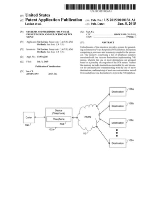
- 99. US 2015/0010136A1 screen in the environment of FIG. 41, in accordance with another embodiment ofthe invention; 0102 FIG.46 illustratesexemplaryfunctioningofthepor table device connected to a picture frame in the environment of FIG. 41, in accordance with another embodiment of the invention; 0103 FIG.47illustratesexemplaryfunctioningofthepor table deviceconnected to aGlobal PositioningSystem (GPS) navigation system in the environment of FIG. 41, in accor dance with anotherembodiment ofthe invention; 0104 FIG.48illustratesexemplaryfunctioningofthepor table deviceSuch as the Smartphone connected toaprojector in the environment of FIG. 41, in accordance with another embodiment ofthe invention; 0105 FIG. 49 illustrates exemplary display ofan Interac tive Voice Response (IVR) menu on a large display screen connected to a portable device Such as the Smart phone, in accordance with an embodiment ofthe invention; 0106 FIG. 50 illustrates block diagram of the portable device, in accordance with an embodiment ofthe invention; 0107 FIG. 51 illustrates another block diagram of the portable device, in accordance with an embodiment of the invention; 0108 FIG. 52 illustrates an environmentwherea portable device maybe connectedtoa userdevice, inaccordancewith an embodiment ofthe invention; 0109 FIG. 53 illustrates an environmentwherea portable device maybe connectedtoa userdevice, inaccordancewith anotherembodiment ofthe invention; 0110 FIG.54 illustratesexemplaryfunctioningofthepor table deviceconnected to a mobilephone in the environment ofFIG. 52 or FIG. 53, in accordance with an embodiment of the invention; 0111 FIG.55 illustratesexemplaryfunctioningofthepor table device connected to a mobile phone and a projector in the environment of FIG. 52 or FIG. 53, in accordance with another embodiment ofthe invention; 0112 FIG.56illustratesanotherexemplary functioningof the portable device connected to a mobile phone and a large screen in the environment of FIG. 52 or FIG. 53, in accor dance with anotherembodiment ofthe invention; 0113 FIG.57illustratesanotherexemplary functioningof the portable device connected to a mobile phone and a tele vision in the environment of FIG. 52 or FIG. 53, in accor dance with anotherembodiment ofthe invention; 0114 FIG.58illustratesexemplaryfunctioningofthepor table device connected to a mobile phone and a laptop in the environment of FIG. 52 or FIG. 53, in accordance with another embodiment ofthe invention; 0115 FIG.59illustratesanotherexemplary functioningof the portable device connected to a picture frame and a wired telephonein theenvironmentofFIG. 52orFIG. 53, in accor dance with anotherembodiment ofthe invention; 0116 FIG. 60 illustratesexemplaryfunctioningofthepor table device connected to a mobile phoneand a GPS naviga tion system in the environment of FIG. 52 or FIG. 53, in accordance with another embodiment ofthe invention; 0117 FIG. 61 illustrates anexemplary displayofan Inter active Voice Response menu (IVR) on a large display Screen connectedtoaportabledeviceandauserdeviceSuchas Smart phone, in accordance with an embodiment ofthe invention; 0118 FIG. 62 illustrates a block diagram of portable device5202,inaccordancewith an embodimentoftheinven tion; Jan. 8, 2015 0119 FIG. 63 isa flowchartillustratingthe functioningof portable device 4102, in accordance with an embodiment of the invention; I0120 FIGS.64Aand64Billustratesaflowchartforimple menting the portable device in the environment of FIG. 52 and FIG. 53, in accordancewith an embodimentoftheinven tion; I0121 FIG. 65 illustrates an exemplary functioning of Visuphone for displaying one or more contact options at a device, in accordance with an embodiment ofthe invention; 0.122 FIG. 66 illustrates change ofdisplay at user device 102, whena userselects acontact option, in accordance with an embodiment ofthe invention; I0123 FIG. 67 illustrates an exemplary functioning of Visuphone for displaying one or more contact options at a device, inaccordance withanotherembodimentoftheinven tion; 0.124 FIG. 68 illustrates change in display at device 102 based onselectionofacontactoption byauserofdevice 102. in accordance with an embodiment ofthe invention; and 0.125 FIG. 69 illustrates a flow diagram illustrating an exemplary functioningoftheVisuphonefordisplayingoneor more contact options at a device, in accordance with an embodiment ofthe invention. DETAILED DESCRIPTION OF THE INVENTION 0.126 Illustrative embodiments ofthe invention now will be described more fully hereinafter with reference to the accompanyingdrawings, in which Some, but not all embodi ments ofthe invention are shown. Indeed, the invention may be embodied in many different forms and should not be construed as limited to the embodiments set forth herein; rather,theseembodimentsareprovidedsothatthisdisclosure willsatisfyapplicablelegal requirements. Likenumbers refer to like elements throughout. I0127 FIG. 1A illustrates an exemplary environment where variousembodimentsoftheinvention may function.A device 102a can be used by a caller 106 for connecting to destinations 108a-n. Device 102a can be a telecommunica tion device that can connect directly to a Public Switched Telephone Network (PSTN) 110. A person skilled in the art willappreciate,thatdevice 102a can also connectto aprivate telephone exchange. Examples of device 102a include, but not limitedto,a mobilephone, aSmartphone, atelephone, or any other device capable of Voice or data communication. Each ofdestinations 108a-n may include one or more Inter active Voice Response (IVR) menus. Further, each ofdesti nations 108a-n may haveoneor moreassociatedphone num bers. When caller 106 dials a phone numberofa destination and connects to any destination from destinations 108a-n, an audible IVR menu may be played to caller 106. Each of destinations 108a-n can have different and more than one audibleIVR menus. Forexample,IVR menusofbankmaybe completely different from that ofa hospital. Typically, the audible IVR menu provided by destinations 108a-n com prises audible options or instructions. Caller 106 may be required to select variousoptions from theaudible IVR menu to obtainthe requiredinformationorresourceorservicefrom the dialed destination. Various types ofdestinations 108a-n that implement the audible IVR menu include, for example, banks, hotels, fast-food outlets, utility services providers, corporate offices, and so forth. 0128. In an embodiment, device 102a includes a Visu phone 104thatcan displayavisual IVR menuondevice 102a
- 100. US 2015/0010136A1 corresponding to the audible IVR menu based on a phone number of the destination to be connected. Visuphone 104 may be hardware, an application stored as Software, a firm ware on device 102a, or a combination thereof. Thereafter, caller 106 can select the options of the audible IVR menu fromthevisualdisplaywithouttherequirementtolisten tothe audibleinstructions. Further,Visuphone 104 may displayone or more options based on the dialed destination. Exemplary audible IVR menu at destination 108a and a corresponding visual IVR menu are explained in detail in conjunction with FIGS. 2A and 2B. 0129. Inanembodimentofthe invention,device 102a can request for updates from a server through a communication network.Theservermay maintaintheupdatedinformationof destinationsandtheirassociatedproperties.This mayhappen in a case when requested information is not available on the dialed destination. The communication network can include more than one device. Examples ofthe communication net work include, but are not limited to, the Network, PSTN, LocalAreaNetwork(LAN),WideAreaNetwork(WAN),and so forth. 0130 FIG. 1B illustrates another exemplary environment where various embodiments ofthe invention may function. As shown, device 102bcan bea device thatcan be connected directly to a network 112. Examples ofdevice 102b include, butare not limitedto,apersonal computer,alaptop,a mobile phone, a Smart-phone, a fixed line telephone, Voice Over Internet Protocol (VOIP) phone or other devices capable of Voiceordatacommunication. Device102b may include vari ousapplications orcomputerprograms thatenablecaller 106 to use device 102b for connecting to any of destinations 108a-n through PSTN 110 over network 112. For example, the applications may be VOIP applications, such as but not limited to, Skype, Magic Jack, Google Talk and so forth. A gateway 116 can be used to interconnect PSTN 110 and network112.Network112 mayincludeanywiredorwireless network. Examples ofnetwork 112 include, but are not lim ited to, a Local Area Network (LAN), a Wide Area Network (WAN), a Wi-Fi network, and so forth. As discussed with reference to FIG. 1A, destinations 108a-n can present the audible IVR to caller 106. Device 102b includes Visuphone 104b that displays a visual IVR menu on device 102b corre sponding to theaudible IVR menu based on a phone number of the destination to be connected. Further, Visuphone 104 may display one or more options for communication on device 102b. 0131 FIG. 1C illustrates yet another exemplary environ ment where various embodiments oftheinvention may func tion. As shown, device 102C can be connected to PSTN 110 through network 112 or through the cellular network 111. Various service providers provide multiple or overlapping services to customers. For example, cable television service provider mayalsoprovidephoneandInternet service, optical Internet provider may also provide phone or television ser vices, WiMax service providers that provide phone service, and so forth. Network 112 may be any service provider that provides such services, for example, but not limited to, cell phone services, wireless services, Internet services, cable television services, or various combinations ofthe above or other type ofservices. As discussed with reference to FIG. 1A, destinations 108a-n presents the audible IVR to caller 106. Device 102c includes Visuphone 104 that displays a visualIVRmenu ondevice 102bcorrespondingtotheaudible IVR menu based on a phone numberofthe destination to be Jan. 8, 2015 connected. Further, Visuphone 104 may display other com munication options to caller 106. 0.132. In an embodiment ofthe invention, Visuphone 104 may call the dialed destination based on the predefined call ing informationautomatically. Inanembodiment,Visuphone 104 may keep on calling to the dialed destination until the requested information is received. In an embodiment, the dialed destination may request the information requested by Visuphone 104 of device 102c (or 102a or 102b), from a server ofthe communication network. Thereafter, the dialed destination may send the information received from the server to Visuphone 104 ofdevice 102c. Further, Visuphone 104 may save and/or display the received information at device 102C. 0.133 FIG. 2A illustrates an exemplaryaudible IVR menu 222aat destination 108a, in accordance with anembodiment ofaninvention.Apersonskilledintheartwillappreciatethat audible IVR menu 222a is an exemplary graphical represen tation of the audible instructions presented by destination 108a forthesakeofexplanationandis notanactualgraphical display. Forexplanation, assumingthat destination 108a is a pizzeriathatprovideshomedelivery andtakesawayservices. Caller 106 connects to destination 108a by dialing a board phone number 202a. Subsequently, various options of audible IVR menu 222a areplayed tocaller 106.The various options includean option 204a thatplays an audible instruc tion, “press 2 for pizza order, an option 206a that plays an audibleinstruction,“press3 fororderstatus’, an option 220a that plays an audible instruction, “press 0 for main menu'. Caller 106 can select an option by pressing from device 102, a button corresponding tothe instructions in theaudible IVR menu. Subsequently, the selected options are transmitted to the destination and the menu is advanced if there are any furtheroptions.Alternatively the display can presentthe next layer of menu options to give the caller better view ofthe option domain and allow even fasterinterfacebetween caller and the IVR. I0134) For example, selection ofoption 204a presents an option 208a that plays an audible instruction, “press 1 for Veg and an option 210a that plays an audible instruction, “press 2 for non-veg is played. Similarly, selecting option 208a or 210a presents or option 214a that plays an audible instruction, “press 1 forhome delivery”, an option 216a that plays an audible instruction, “press 2 for take away”. Simi larly, selection ofoption 206a presents an option 212a that plays anaudible instruction, “press 1 totalkto an executive'. I0135). Options 204a, 206a, 208a, 210a, 212a, 214a, and 216a arepart ofa main menu 218.a. Main menu 218a can be repeated by selecting option 220a by caller 106. Caller 106 may repeatmain menu218a forexample,in caseofa mistake in selection. Therefore, caller 106 directly interacting with audible IVR menu 222a may be required to listen to all or various audible options before executing a desired action. However, theinteraction is simplifiedbyVisuphone 104, that presents a visual IVR menu 222btocaller 106 corresponding to audible IVR menu 222a, as explained with reference to FIG. 2B. 0.136 Further,each ofdestinations 108a-n mayhavemore than one audio IVR menus. Therefore, different visual IVR menuscorrespondingtooneormoreaudio IVR menuscanbe availableforeach ofdestinations 108a-n. Inan embodiment, device 102 may include morethan one visual IVR menus for each destination of destinations 108a-n based on the time. Herein after device 102 collectively refers to device 102a,