SlideShare a Scribd company logo
1 of 19
Download to read offline
(12) United States Patent
USOO902113OB1
(10) Patent No.: US 9,021,130 B1
Sahay et al. (45) Date of Patent: Apr. 28, 2015
(54) PHOTONIC LINE SHARING FOR 5. R : 3. Streal . . . . . . . . . . . . . . . .$8.5- W reenberg et al.
HIGH-SPEED ROUTERS 6,970,942 B1 * 1 1/2005 King et al. ......... TO9,238
7,177.544 B1* 2/2007 Wada et al. ..................... 398,51
(75) Inventors: Vasant Sahay, Sunnyvale, CA (US); Tal 7,493.410 B2 * 2/2009 Moore et al. ... TO9,238
Lavian, Sunnyvale, CA (US); Bruce 2004/0015590 A1* 1/2004 Nagami et al. . 709/227
2004/O184615 A1* 9,2004 Elliott et al. ....... ... 380/283
Schofield, Tyngsboro, MA (US) 2005/0030951 A1 2/2005 Maciocco et al. ......... 370,395.2
(73) Assignee: RPX Clearinghouse LLC, San * cited by examiner
Francisco, CA (US)
Primary Examiner— Derrick Ferris
(*) Notice: Subject to any disclaimer, the term ofthis Assistant Examiner— Scott M Sciacca
patent is extended or adjusted under 35 (74) Attorney, Agent, or Firm — Christopher & Weisberg,
U.S.C. 154(b) by 3680 days. P.A.
(21) Appl. No.: 10/750,531 (57) ABSTRACT
1-1. Embodiments ofthe present invention present a methodand
(22) Filed: Dec. 31, 2003 apparatus for photonic line sharing for high-speed routers.
(51) Int. Cl Photonic Switches receive high-speed optical data streams
we and produce the data streams to a routeroperating accordingG06F 5/73 (2006.01) toroutinglogicandproduceoptical datastreamsaccordingtoH04L 2/70 (2013.01)
H04L 2/28 (2006.01) destination addresses stored in the datapackets. Eachphoto
(52) U.S. Cl nicSwitch canbeconfiguredas oneofa 1:N multiplexeroran
AVe. we M:N cross-connect switch. In one embodiment, optical data
CPC - - - - - - - - - - - - - - grgr. H04L 12/28 (2013.01) is converted to electrical data prior to routing, while an alter
(58) Field ofClassification Search nate embodiment routes only optical data. Another embodi
USPC .................. 709/238,239, 240,244; 370/351; ment transfers large Volumes ofhigh-speed data through an
398/45 49, 50, 57 opticalbypass lineinacircuitSwitched networktobypassthe
Seeapplication file for complete search history. switch fabric thereby routing the data packets directly to the
56 Ref Cited destination.Anedgedeviceselects oneofthepacketSwitched
(56) eferences Cite network or the circuit switched network. The bypass
U.S. PATENT DOCUMENTS resources are released when the large Volume ofhigh-speed
data is transferred.
5,757,795 A * 5/1998 Schnell ........................ 370,392
5,828.475 A * 10/1998 Bennett etal. .................. 398,52 21 Claims, 11 Drawing Sheets
260
N data packet network
262 routers
fiberoptic link 278
Oer OOC
EDGE device 268 p
local user fiber optic backbone
270 fiber optic backbone
276
light path ("circuit
Switched" network)
266
combined circuitswitched and data packet
networkwith multi-stage photonic switching
US 9,021,130 B1Sheet 1 of 11Apr. 28, 2015U.S. Patent
US 9,021,130 B1Sheet 2 of 11Apr. 28, 2015U.S. Patent
99JanuasKuepuoO3S
up!MS oluo)Oud
0/
íp-,,,,,,)
US 9,021,130 B1Sheet 3 of 11Apr. 28, 2015U.S. Patent
u0)MS oluo)Oud N-O-W
US 9,021,130 B1Sheet 4 of 11Apr. 28, 2015U.S. Patent
up MS oluoloud indino
96quod
88
OMS ouOOud indu
Seu]]
US 9,021,130 B1Sheet 5 of 11Apr. 28, 2015U.S. Patent
US 9,021,130 B1Sheet 6 of 11Apr. 28, 2015U.S. Patent
US 9,021,130 B1Sheet 7 of 11Apr. 28, 2015U.S. Patent
US 9,021,130 B1Sheet 8 of 11Apr. 28, 2015U.S. Patent
uol?SOd10160||
US 9,021,130 B1Sheet 9 of 11Apr. 28, 2015U.S. Patent
OZZ
OOZ
US 9,021,130 B1Sheet 10 of 11Apr. 28, 2015U.S. Patent
uo. MS oluoroud indino
uo. MS Ouoloud indu
US 9,021,130 B1U.S. Patent
US 9,021,130 B1
1.
PHOTONIC LINE SHARING FOR
HIGH-SPEED ROUTERS
BACKGROUND
1. Technical Field
Thepresent invention relates to data packet networks and,
more particularly, the presentinvention relates to high-speed
routing ofdata packets in the data packet network.
2. Related Art
Communication service providers, as well as networkSer
Vice providers, face Some difficult challenges as the various
networks are increasingly modified to work together to pro
vide seamless end-to-end connectivity across the various
platforms and protocols. Ever-increasing residential dial-up
Subscribers and broadband Subscribers demand increasing
network speed. To meet this demand, network service pro
viders are deploying a large number of complex, port-dense
NetworkAccess Servers (NAS) to handle thousands ofindi
vidual dial-up connections. As such, Small and large, as well
as privateandpublic, data packet networks arebeing created
to enable users to establish point-to-point connections inde
pendent of terminal type and location. Traditional circuit
switched voice networks have paved the way forthe creation
ofdata packet networks as users loaded the Voice networks
trying to transmit data, including streaming data (video and
voice). Initially, traditional Public Switched Telephone Net
works (PSTNs) were used for data transmissions but have
been largely supplanted by data packet networks, including
various versions ofthe “Internet” forpurposes ofdata trans
port.
DuringtheInternetboom,fiberoptic cablewasinstalledto
meettheincreasingdemand forhigh-speedaccess to the data
packet network.With fiberopticcable,optical networkshave
been developed in various forms utilizing various transport
technologies. For example, dense wavelength division mul
tiplexing (DWDM) is being used in optical networks to sig
nificantly increase throughput and, more generally, to trans
port data from point to point. High-speed transceivers up to
OC-192 (OpticalCarrier,9.6 gigabits-per-second)havebeen
installed to meet the increasing demand. The expectation
beingthatthehigh cost ofinstalling and maintaining ahigh
speed network will be recoveredas moreusers demand more
bandwidth. The Internet business climate is changing and
demands are being put on operators to provide bandwidth
while optimizing the use of their networks to reduce the
operating costs. Network operators and networkservicepro
vidersthus needa moreeconomical methodtousetheexpen
sive resources.
Bandwidth is notonly a concern to individuals,butalso to
service providers. From the operator's perspective, band
width is the key to the number of users a communication
system can Supportat any given time, theamount ofdatathat
canbetransportedviathecommunicationsystematanygiven
time, and the speed at which the data can be transported.
Bandwidth thus translates intoa numberofpotential custom
ers and revenue. Forthis reason, companies spend billions of
dollars annually to develop equipment to increase the band
width of communication systems, such as the Public
SwitchedTelephoneNetwork(PSTN), wireless communica
tion systems, wire line communication systems, and/or the
Internet.
One key standard that increases the bandwidth ofcommu
nication systems, is SONET (Synchronous Optical NET
work). SONET was created to provide a cost effective plat
form for multi-vendor internetworking and offers the
advantages ofback-to-back multiplexing, compatibility with
10
15
25
30
35
40
45
50
55
60
65
2
other standards, and ultra high performance. In particular,
SONET is a transmission technology, which resides in the
physicallayerandcanbeusedto carry awide varietyoftypes
of traffic, including ATM (Asynchronous Transfer Mode)
cells. In addition, theSONETphysicallayermaybeusedin a
wide variety ofapplications, including LAN-to-LAN inter
connections, host-to-host interconnections, video conferenc
ing, team engineering, distributed processing, and advanced
Scientific research.
The basic building blocks of a SONET system are 125
microsecond frames that come in two sizes ofSynchronous
Transport Signal (STS) frames: the STS-1 frame and the
STS-3 frame. The STS-1 frame provides a bit rate of51.84
Mbps while the STS-3 frame provides a bit rate of 155.52
Mbps. Once an STS frame is converted from an electrical
format into an optical format for transmission, the frame is
then referred to as an Optical Carrier (OC), but still has the
same bit rate as the STS frame.
As mentioned, SONET is a transmission technology,
which differs from switchingtechnology. Switchingtechnol
ogy is concerned with how data is routedacross the network,
whiletransmission technology is concerned with how datais
encoded and transported across the network. SONET, there
fore, separates the overheadofSwitchingtechnology, Such as
ATMfrom thepayloadfields(i.e., thedata). As such,SONET
is not applied directly to the Switching devices ofa network,
but is used to specify the interfacebetween the switches that
are linked by optical fibers. Thus, standard ATM or LAN
switches are equipped with a SONET interface in order to
comply with the SONET specification.
As the demand for bandwidth escalates, various network
elements are being made to receive and transmit optical data
forincreasedperformance. Opticalequipmentandtransceiv
ers, forusein networkelements suchas routers,however, are
expensive. Because a router has many different ports, using
an opticaltransceiverforeachportresultsinthe useofoptical
technologyforrouters beingvery expensive. What is needed,
therefore,isarouterwithopticaltransceiversthatiseconomi
cally feasible.
BRIEF SUMMARY OF THE INVENTION
Themethodandapparatus ofthepresentinvention reduces
thecostofoperatingand maintaininghigh-speedopticalfiber
networks by using scaleablephotonic Switches to selectively
couple fiber lines to a shared optical transceiver port and
optical router. The photonic Switches share an optical trans
ceiverinputoroutputwith multiple fiber lines thereby reduc
ing the number ofoptical transceivers needed to service the
multiple fiberlines. Unusedorlightly used fiberlines may be
reduced through the use of photonic Switches to carry data
packets. Moreover,dedicatedbackup fibermaybereducedas
one backup fiber may be used to provide redundancy for
multiple primary fibers.
A routing system of the present invention comprises at
least one high data rate input optical port that receives high
datarateopticaldataandconvertstheopticaldatatoelectrical
data,Switchfabriccoupledto receivetheelectrical dataandto
switch the electrical data to route the electrical data on a
packet-by-packet basis to an output optical port, and at least
onephotonic Switch coupled to aplurality ofoptical ports.A
plurality offiberlinesarecoupledtotheinputopticalportand
optical outputportofthephotonic Switchto transmitthedata
packetsfromasourcetoadestinationstoredinthedatapacket
header.
Switch intelligence comprising one ofa data packet rout
ing system controllerandroutinglogicevaluatesthehighdata
US 9,021,130 B1
3
rate optical data to determine an efficient transport mecha
nism. The transfer ofa small volume ofdata may be routed
through the datapacket network. The routinglogic maintains
a mapping table foreach inputandoutputphotonic Switch to
optimize the routing ofdata packets based on the destination
IP address. The switch intelligence transmits control com
mands to route the data packet through the input photonic
Switch and the output optical Switch.
In one embodiment, the optical data is converted to elec
trical databefore routingthrough thedata packet network. In
another embodiment the data packet stays in the optical
domain duringthe routing and Switching process. Large data
transfers are moreefficiently transportedthrough a dedicated
optical path, or light path, using a mechanism similar to
circuitSwitchinginwhichadedicatedend-to-endopticalpath
is established from the source to the destination. In one
embodiment ofthepresent invention, a large Volume ofdata
is circuitSwitchedthroughan opticalbypass linetobypassthe
packet Switched circuits to reducing loading on the data
packet network. The above-referenced description of the
Summary ofthe invention captures some, but not all, ofthe
various aspects of the present invention. The claims are
directed to some of the various other embodiments of the
subject matter towards which the present invention is
directed. In addition, other aspects, advantages and novel
features ofthe invention will become apparent from the fol
lowingdetailed description oftheinvention when considered
in conjunction with the accompanying drawings.
BRIEF DESCRIPTION OF THE SEVERAL
VIEWS OF THE DRAWINGS
FIG. 1 is a functional block diagram of a data packet
network;
FIGS.2Aand2Bshowadual redundantopticalconnection
and one advantage ofphotonic line sharing accordingto one
embodiment ofthe present invention, respectively;
FIG. 3 illustrates line sharing with a photonic switch
according to one embodiment ofthe present invention;
FIG. 4 illustrates a routing system according to one
embodiment ofthe present invention;
FIG.5 illustratesadatapacketroutingsystem accordingto
oneembodiment ofthe present invention:
FIG. 6 is a functional block diagram that illustrates one
aspect ofa data packet routing system controller,
FIG. 7 illustrates a photonic switch mapping tableaccord
ing to one embodiment ofthe present invention;
FIG. 8 illustrates operation ofan optical binary switch;
FIG. 9 isa flowchartfora methodofroutinga data packet
in a high-speed routing system in one embodiment of the
present invention;
FIG.10illustratesamulti-stagephotonicSwitchingsystem
according to one embodiment ofthe present invention; and
FIG. 11 isaschematic blockdiagram ofacombinedcircuit
Switched and data packet network with multi-stagephotonic
Switchingaccordingto oneembodiment ofthepresentinven
tion.
DETAILED DESCRIPTION OF THE INVENTION
FIG. 1 is a functional block diagram of a data packet
network. Data packet network 10 comprises a number of
networking elements interconnected to transmit and receive
data packets. Shown are several regional Network Service
Providers (NSP)connectedbyfiberopticbackbonestocreate
a portion ofan interconnected data packet network, i.e., the
Internet. Regional NSP 14, regional NSP 18, and regional
10
15
25
30
35
40
45
50
55
60
65
4
NSP 22 have high-speed routers (not shown) to route data
packets between each network over a fiber optic backbone.
Each router maintains a configuration table entry for every
router with which itcan connect. Each ofthe routerentries in
the configuration table describes a range of addresses con
nected to each router. The router accesses the configuration
table entry to determine if the router can forward the data
packet to the destination.
A local NSP 26 connects to regional NSP 14 through
NetworkAccessPoint(NAP)30 toallownetworksubscribers
to access the datapacket network. Local user34 connects to
local NSP26 overa broadband connection includingeithera
Digital SubscriberLine(DSL) ora cable modem.Abusiness
Local Area Network(LAN)38 maintains a fiberoptic linkto
local NSP26overa dedicated fiberoptic linkand also main
tainsaT-1 (Trunk Level 1) line forbackup. Users ofbusiness
LAN38andlocaluser34canseamlesslyconnecttoanyother
entity in the data packet network using a variety ofnetwork
ing protocols such as TCP/IP.
Connected to regional NSP 22 through NAP 42, a service
provider46 providesa numberofnetworkservices including
nightly backup services and secure storage for confidential
information. The distributed design of the data packet net
workallows service provider46 to provide services to busi
nesses, such as business LAN 38, though not directly con
nected to the same network service provider or NAP. This
aspectofthe distributed design ofthe data packet network is
especiallydesirableformaintaining multipleremotebackups
in case ofa tragic event such as a terroristattack.
The present invention reduces the cost for network opera
tors, such as serviceprovider46 and local NSP 26, by reduc
ingthe costofoperating redundantand/orunused fiberoptic
lines through photonic line sharing. High-speed routers for
high-speedopticaldatarates(OC-192,etc.)aresharedamong
lightly used fiber optic lines with sporadic heavy volume by
Switching data packets through photonic Switchesbasedon a
destination address.
FIGS. 2Aand2Bshowadual redundantopticalconnection
and one advantage of photonic line sharing, respectively,
according to one embodiment of the present invention. As
shown in FIG. 2A, a high-speed router 50 includes two 10
Gbps optical transceivers. Each opticaltransceiverSupports a
linkto a serverwherein onelinkis an activeprimary linkand
theotherisabackuporstandbylink.Aprimary link54carries
data packet traffic between the high-speed router 50 and a
primary server58,whileasecondstandby link 62isa standby
link to a secondary server 66. In this configuration, standby
link 62 and secondary server 66 are redundant backups to
primary server58 and primary link54. Accordingly, the sec
ond optical transceiveris not used unless there is a failure on
theprimary servercircuit.Thecostofmaintainingthebackup
system includes, therefore, an expensive 10 Gbps optical
transceiverthat is only used for backup purposes. Increasing
competition intoday's marketplace is driving networkopera
tors to reduce costs. One method to reduce cost is to reduce
the use of expensive optical transceivers that otherwise sit
idle.
FIG. 2B illustrates photonic line sharing according to one
embodiment ofthe present invention. In the configuration of
FIG. 2B, the backup optical transceiver has been removed.
The primary optical transceiver is coupled to a photonic
switch 70 that is further coupled to primary link 54 and to
standby link62. Photonic switch70 functions to routeoptical
data eitherto primary link54 ortostandby link62 depending
ona photonic switch control. Photonic switch70 is much less
expensivethana 10Gbps.Accordingly,the networkoperator
has substantially reduced the cost to the server's operator for
US 9,021,130 B1
5
Supporting the dual redundant system without seriously
impairing the functionality ofthe system.
One aspect ofthe present invention is to reduce costs by
replacing expensive optical transceivers with inexpensive
photonic switches. Photonic switches are switches that con
duct light, or photons, instead of electrons. Using Small
micro-mirrors or controllable opaque devices based on sili
contechnology,thephotonicSwitchescreatelogicalonesand
Zeros by turning light on and off. Electrical Switches are
typically composed oftransistors and resistors and, as such,
consume electricity and produce heat. Photonic Switches
exhibit low power dissipation, low optical loss and, because
of their Small size, offer a reduction in equipment space
“footprint. Additionally, by switching light, the photonic
Switch operates equally well with low and high data rates so
that they are bit-rateindependent. Electrical switches exhibit
Some high frequency loss and are bit-rate dependent and
thereforeless desirable. Photonic switches can beconfigured
as multiplexers or as digital cross-connect Switches to
increase the port density ofhigh-speed routers in an optical
network.
Another method to reduce cost is to spread the cost of
installing and maintaining optical fiber links across all the
users ofthefiberlink. In theexampleofFIG. 2A, the server's
operator is responsible for the cost of two dedicated fiber
optic links, namely, primary link 54 and the unused standby
link 62. By using theoptical transceiverand the standby link
unused in other applications, the cost of maintaining the
fiber-optic link is reduced.
FIG. 3 illustrates line sharing with a photonic switch
accordingto oneembodimentofthepresent invention. Inthis
example, a photonic switch 74 is configured as an M-to-N
photonic cross-connect Switch, where N is greaterthan M.A
high-speed router 78 includes a plurality (M) of 10 Gbps
optical transceiversoperably coupledtotheinput ofphotonic
switch 74. Photonic switch 74 routes the data packets to
network destinations (1, 2, ...N) in data packet network 10.
In this configuration, each optical transceiver can route data
packets to any network destination by the proper control of
photonic switch 74. The routing and control ofthe photonic
Switch will be described in relation to FIG. 4 and FIG. 5.
Becausethephotonic Switch is less expensive to expandthan
is adding optical transceivers, fewer optical transceivers are
needed to Support the data packet routing through the photo
nic Switchtothe datapacket network. In a normal datapacket
flow, the routing ofdatapackets through thephotonic Switch
will be transparent to most network users.
FIG. 4 illustrates a routing system according to one
embodiment of the present invention. A routing system 80
comprises an input photonic Switch 84, an input optical port
88, a switch fabric 92, an output optical port 96, an output
photonic switch 100, and a controller 104.
Input photonic switch 84 functions to switch optical data
from ingoing fiber lines to input optical port 88 according to
controlcommandsreceivedfromcontroller104. Inputoptical
port 88 receives high data rateoptical data from input photo
nic switch 84 and converts the optical data to electrical data
using techniques known to one of average skill in the art.
Switch fabric 92 routes the electrical data, as received from
input optical port 88, on a packet-by-packet basis according
to a destination address stored in the data packet headerand
routing configuration rules. Similarly, output optical port96
receives electrical data and converts it to optical data. Con
troller 104 includes computer instructions that define the
routinglogicofroutingsystem80. Basedon ingoingfiberline
conditions and outgoing fiber line conditions, controller 104
issues control commands to input photonic Switch 84 and
10
15
25
30
35
40
45
50
55
60
65
6
output photonic switch 100 to route the data packet to the
destinationaddress containedinthedatapacketheaderbythe
bestrouteavailable. Becauselineconditionschangeandrout
ing elements can drop out ofservice, routing system 80 con
tinuously updates the mapping table for the most efficient
routingofdatapackets. As isknownto one ofaverage skill in
the art, each data packet comprising the complete transmis
sion may be routedby different paths through thedata packet
network. Output photonic switch 100 is operably coupled to
receive the control commands from controller 104 and to
routethe optical datato theproper outgoing fiberlinesandto
theproperdestination.Theoperation ofcontroller104willbe
discussed in relation to FIG. 6.
FIG.5illustratesadatapacketrouting system accordingto
oneembodimentofthepresentinvention. Datapacketrouting
system 110 comprisesan ingoing optical Switch module 114,
a router 118, an outgoing optical Switch module 122, and a
bypass and routing logic module 126. As may be seen, this
embodiment includes theoptical switches as partofthe rout
ing system. Ingoingoptical dataisreceivedoveraplurality of
ingoingoptical fiberlinesand is coupledto a firstplurality of
inputportstoingoingopticalSwitch module 114.Theingoing
optical datais routedby ingoingoptical Switch module114to
a first plurality ofinput ports according to commands issued
frombypassand routinglogic module126. Router118directs
the data packets to the data packet network according to a
destination IPaddress stored in the datapacketheader.Addi
tionally,router118routesdatapacketstoasecondpluralityof
inputportstooutgoingopticalSwitchmodule122,whichthen
routesthedatapacketsaccordingtoSwitchsettingscontrolled
bybypassandroutinglogic module126.Theoutgoingoptical
dataisfurthercoupledfromasecond pluralityofoutputports
to outgoing fiber lines by control commands issued from
bypass and routing logic module 126.
Routing of normal data packets is accomplished by data
packetrouting system 110asis knownbyone ofaverageskill
in the art. Some applications require transferring of large
Volumes of packet data. This large Volume of data places a
load on the routing network beyond the design intent ofthe
data packet network. More specifically, each data packet is
typically 1.5 kilobits, thus an application transferring a large
Volumeofdata, forexampleaone-gigabytefile,containsover
600,000 data packets. Each router in the routing path looks
into each data packet header to make the next-hop decision.
Theprocess is repeatedover 600,000 times for each routerin
the routing path. One aspect of the present invention is to
reducetheload on thepacket Switched networkby bypassing
the data packet routingsystem (router118) for very largefile
transfers (multi-gigabyte and multi-terabyte). Bypass and
routinglogic 126 selects largefiletransfers forcircuitSwitch
ingoveradedicatedend-to-endopticallightpath (bypass line
134) to reduce loading on the data packet routing system
(router 118). As can be seen in FIG. 5, a client host 130
runningan externalapplication istransferringa large Volume
of data through data packet routing system 110. In this
example, routing logic module 126, in communication with
clienthost130, switches the largevolumeofdataoverbypass
line 134. The communication between client host 130 and
bypass androutinglogic module126 maybeoveran Ethernet
connection or a system signal line. Since router 118 will not
be inspecting the data packets from client host 130, bypass
and routing logic module 126 must receive a signal to start
and stop bypass routing. Client host 130 may set bypass
start-stop routing by time, application, provider, request, or
forotherreasons. Forexample, routingbytimewouldaccom
modate backup operations wherein a known Volume of data
will be transferred in a known amount of time. Generally,
US 9,021,130 B1
7
bypass routing involves routing the large Volumes of data
from a number of known source addresses to a number of
predefined destination addresses. Bypass and routing logic
module 126 is shown as a component ofdata packet routing
system 110. However, it may be designed external to data
packet routing system 110. Such as a card in an optical rack
controlling a plurality ofoptical Switch modules. Addition
ally, bypass and routing logic module 126 may be formed in
a controller comprising an Application Specific Integrated
Circuit(ASIC)orFieldProgrammableGateArray (FPGA)as
is known ofby one ofaverage skill in the art.
FIG. 6 is a functional block diagram that illustrates one
aspect ofa data packet routing system controller. Referring
now to FIG. 6, data packet routing system controller 140
includesaprocessor144thatis coupledto communicateover
abus 148.Abuscontroller152controls communications over
bus 148. Memory 156 further is coupled to bus 148 and
includescomputerinstructionsthatareretrievedbyprocessor
144 over bus 148 for execution. The computer instructions
withinmemory 156definetheoperationallogicofdatapacket
routing system controller 140. For example, memory 156
includes computer instructions that define the data packet
routing system controller operational logic. Specifically, the
computer instructions within memory 156 define routing
logic for generating control commands to Switch each pho
tonic Switch operably coupled to data packet routing system
controller 140. More specifically, computer instructions
within memory 156 define routing logic for mapping desti
nation IP addresses to output port and photonic Switch posi
tions based on the IP address within the data packet header.
Bus controller 152 is furthercoupled to a communications
port 160through which datapacket routing system controller
140 transmits control commands to the photonic Switches.
Thus,whenprocessor144retrievesthecomputerinstructions
stored within memory 156 and executes them to determine
that it should generate control commands to the photonic
Switches, processor 144 formats the signal and transmits it
over bus 148 through bus controller 152 and out communi
cations port 160 for transmission to the photonic switches.
Data packet routing system controller 140 may be formed
as a separate logic device or it may be formed internally
withinthedatapacketroutingsystem. Further,thedatapacket
routing system controller may be formed ofother technolo
gies such as ASICs or FPGAs as is known to one ofaverage
skill in the art.
FIG. 7 illustrates a photonic switch mapping tableaccord
ing to one embodiment ofthe present invention. The intelli
gencecontrollingeach photonic Switch maintains a mapping
table similarto the configuration table maintained by routers
in the data packet network. The destination IP address, as
defined in the data packetheader, ofeach datapacket routed
throughthephotonic Switchisenteredintothe mappingtable.
The input port switch information and output port switch
information used in routing the data packet is stored in the
switch andswitch position fields, respectively.The inputand
outputportinformation is continuously updatedaccordingto
known inputandoutputlineconditionssuchaslinetrafficand
router status. The next two fields are variable length fields.
The switch field contains anentry foreach switch used in the
photonic switch. This allows for multiple input and output
switches in a multi-stage switch. The switch position field
contains an integer value for every entry in the switch field
and represents the switch position of the respective switch
used in routing the data packetthrough the photonic Switch.
FIG. 8 illustrates operation ofan optical binary photonic
switch. The photonic switch comprises a plurality ofswitch
ing modules thatare usedto route input optical data received
10
15
25
30
35
40
45
50
55
60
65
8
atan input optical port to aselected output optical port. Each
Switching module comprisesaplurality ofoptical Switchesto
route thedatapacket. FIG. 8illustratesasimplebinaryswitch
fordiscussionpurposes butis indicativeoftheoptical Switch
ingofthephotonicSwitch.Continuingwiththedescription of
FIG. 8, the binary switch has two states: ON or OFF. The
binary switch comprises a movable mirror 170, a switching
logic module174,a fixedmirror178, a focusinglens182,and
an optical fiber 186 coupled to an optical output.
ThebinarySwitchproducesalogic 1 oralogic0depending
on the position ofmovable mirror 170 controlled by switch
ing logic module 174. The input optical data, illustrated as
light 190, strikes movable mirror 170 andis reflectedto fixed
mirror178when movablemirror170isinthelogic 1 position.
Light 190 is reflected by fixed mirror 178on to focusing lens
182 which concentrates light 190 on the input ofoptic fiber
186. To produce a logic 0, movable mirror 170 is positioned
by switching logic module 174 to reflect light away from
fixed mirror 178. In the logic 1 position the switch isON and
in the logic 0 position the switch is OFF. Switching logic
module 174controls theposition ofmovable mirror 170 as is
known to one ofaverage skill in the art.
Ina more complexSwitch Such as an opticalcross-connect
switch,a movable mirrorreflects light to a selected mirrorof
apluralityoffixedmirrors.Thelightreflectedfromeach fixed
mirroris operably coupledto an optical output ortotheinput
ofanother optical Switch. The coupling ofSuccessive layers
ofopticalSwitchescreatesaphotonicSwitchthatcanfunction
as 1 to N multiplexeroras an M to N cross-connect switch.
FIG. 9 is a flowchart fora methodofroutinga data packet
in a high-speed routing system in one embodiment of the
present invention. The high-speed routing system, compris
ing one or more ingoing photonic Switches and one or more
outgoing photonic Switches, receives a high-speed data
packetstream(step200),overa fiberline,ataphotonicswitch
input port. Each data packet of the high-speed data packet
stream includes an IP destination address in the data packet
header, and the routing system evaluates the destination
address (step 204) of each packet in the high-speed data
packet stream. The routing system, based upon an external
input,determinesa Switchposition ofafirstingoingphotonic
Switch to select one ofaplurality ofinput light streams (step
208) that comprises the high-speed data packet stream. In a
multi-stagephotonicSwitch,theinvention includesdetermin
ing, based upon an external input, a Switch position of a
second ingoing photonic Switch to select one oftheplurality
ofinput light streams to the second ingoing photonic Switch
(step 212). The external input is operably coupled from a
Switch intelligence comprising one ofa routing logic and a
data packet routing system controller. The operation ofthe
data packet routing system controller was previously
described in relation to FIG. 6.
Thehigh-speedrouting system determines,based uponthe
destination address, which output port should transmit the
datapacketandforwardsthedatapackettothecorresponding
output port (step 216). Based upon at least one ofthe desti
nation address and a known output fiber line condition, the
high-speed routing system determines a Switch position ofa
first outgoing photonic Switch (step 220) and produces a
control command to the first outgoing photonic Switch if
necessary(step224).Thecondition oftheoutputfiberlines is
updatedcontinuously and maintainedinthe mappingtableas
previously described in relation to FIG. 7. The high-speed
routingsystem uses this information to determinetherouting
path through the ingoing and outgoing photonic Switches
(step 228). This generally includes determining the switch
positionforasecondoutgoingphotonic Switch,whichsecond
US 9,021,130 B1
9
outgoing photonic Switch is coupled to the first outgoing
photonic Switch and produce the control command to the
second outgoing photonic Switch, if necessary, to cause the
datapacketto becoupledtoacorrectfiberlineinoneembodi
ment ofthe invention.
FIG.10illustratesamulti-stagephotonicSwitchingsystem
according to one embodiment ofthe present invention. This
embodiment expands the number of fiber lines that are
Switched, or cross-connected, from input to output. A single
stagephotonic Switchingsystem, routing system 80 ofFIG. 4
for example, typically receives ingoing data packets over
ingoingfiberlines connected to asingle NAP. Similarly, data
packetsareroutedto an outputportforSwitching to outgoing
fiber lines thatconnect to a singleNAP. Multi-stagephotonic
Switchingsystem230incorporatesapluralityofingoingpho
tonic Switches coupledto receivedatapackets overaplurality
ofingoingfiberlines. Each ofthepluralityoftheingoingfiber
lines connects to a different NAP. A plurality ofoutgoing
photonic Switches is coupled to receive datapackets from an
output photonic Switch. Each of the plurality of outgoing
photonic switchesconnectstoadifferentNAPoveraplurality
ofoutgoing fiber lines.
A first ingoing photonic Switch 234 receives data packets
from a first NAP (not shown) overa firstplurality ofingoing
fiber lines. A second ingoing photonic switch 238 receives
data packets from a second NAP (not shown) over a second
plurality ofingoingfiberlines.Afirstselectedfiberlineofthe
firstplurality ofingoingfiberlines is selectedby first ingoing
photonic switch 234 and connected to a first input ofinput
photonic Switch242accordingtocontrolcommands received
fromSwitchingsystemcontroller246.Asecondselectedfiber
lineofthesecondpluralityofingoingfiberlines isselectedby
second ingoing photonic Switch 238and connected to a sec
ond input ofinput photonic Switch 242 according to control
commands received from Switching system controller 246.
Routing ofdata packets from input photonic Switch 242,
through the optical ports and Switch fabric, to an output
photonic switch 250 is a functional equivalent to the opera
tion of routing system 80 described with respect to FIG. 4.
Continuing with the discussion of FIG. 10, data packets
received by outputphotonic switch 250 are routed according
to information storedin the mappingtable. Switchingsystem
controller 246 switches the data packets received by output
photonic switch 250 to one of a first or second outgoing
photonic switchaccordingto the IPaddress storedin thedata
packet header. The IP address specified in each data packet
header determines which NAP can access the specified IP
address. Switching system controller 246 transmits control
commandsto eitherafirstoutgoingphotonic Switch254orto
a second outgoing photonic Switch 258 to Switch the data
packetto the correct outgoing fiber line ofthe outgoing fiber
lines for routing to the specified NAP.
FIG. 11 isaschematic blockdiagram ofacombinedcircuit
Switched and data packet network with multi-stagephotonic
Switchingaccordingto oneembodiment ofthepresentinven
tion.ThecombinedcircuitSwitchedanddatapacketnetwork,
showngenerally at260, comprises adatapacket network262
and a light path 266 (circuit switched network) operably
coupled to fiberoptic linksbetween an edge device 268anda
destination282.Accesstodatapacketnetwork262 is through
NetworkAccess Point (NAP) 272 and NAP 284. Aplurality
of routers 264 within data packet network 262 route data
packets to destination 282 based on a destination address
stored in the data packet header. Light path 266 comprises a
plurality of dedicated end-to-end optical connections and
photonic switches to efficiently switch data from fiber optic
backbone 276 to fiber optic backbone 280.
10
15
25
30
35
40
45
50
55
60
65
10
A local user270 sendsa largevolumeofdata todestination
282. Edge device 268 is operably coupled to data packet
network 262 (a packet switched network) and to light path
266 (a circuitswitched network)overfiberoptic link274and
fiber optic backbone 276, respectively. Based on the size of
the data transfer, edge device 268 selects one ofthe packet
switched network or thecircuit switched network forthe data
transfer. Data packet network 262 includes a plurality of
routers264toswitchdatapacketsfromNetworkAccessPoint
(NAP)272to NAP284. As is known tooneofaverageskillin
theart, routers264switch datapacketsbetweenNAP272and
NAP 284 based on a destination address stored in the data
packetheader. Eachroutermaintainsa routingtableofopera
tional routers available to receive data packets. Data packets
are forwarded through the path of routers until they reach
destination 282.
Light path 266 is a circuit switched network ofdedicated
end-to-end optical paths and photonic Switches operably
coupled between fiber optic backbone 276 and fiber optic
backbone280. When datais transferred fromlocaluser270 to
destination 282 via lightpath 266,acircuitinlightpath 266 is
establishedorswitchedbetweenfiberopticbackbone276and
fiber optic backbone 280 by established signaling systems.
Thisswitchedcircuitisadedicatedpathfrom edgedevice268
to destination 282 and is maintained until the data transfer is
complete then the switched circuit is disconnected which
releases the Switch resources.
Edge device 268 selects either the data packet networkor
the circuit switched network based on the most efficient
method forthe data transfer. Large Volumes ofdata are typi
cally transferred through circuit switched network 266
because ofthe dedicated connection between local user 270
and destination 282. A smaller size data transfer may be
routed through data packet network 266.
The invention disclosed herein is susceptible to various
modifications and alternative forms. Specific embodiments
thereforehavebeenshownbywayofexampleinthedrawings
and detailed description. It should be understood, however,
that the drawings and detailed description thereto are not
intended to limit the invention to the particular form dis
closed,but onthecontrary,theinvention is to coverall modi
fications,equivalentsandalternatives falling withinthespirit
and scope ofthe present invention as defined by the claims.
Moreover,asoneofaverageskillintheartwillappreciate,the
term “substantially” or “approximately, as may be used
herein, provides an industry-accepted tolerance to its corre
sponding term. Such an industry-accepted tolerance ranges
from lessthan onepercenttotwentypercentand corresponds
to, but is not limited to, component values, integrated circuit
process variations,temperaturevariations,riseandfalltimes,
and/or thermal noise. As one ofaverage skill in the art will
further appreciate, the term “operably coupled, as may be
used herein, includes direct coupling and indirect coupling
via another component, element, circuit, or module where,
for indirect coupling, the intervening component, element,
circuit,ormoduledoes notmodifytheinformation ofasignal
but may adjust its current level, Voltage level, and/or power
level. As one ofaverage skill in the art will also appreciate,
inferred coupling (i.e., where one element is coupled to
another element by inference) includes direct and indirect
couplingbetweentwoelements inthesame manneras "oper
ably coupled'. As one ofaverage skill in the art will further
appreciate, the term "compares favorably, as may be used
herein, indicates that a comparison between two or more
elements, items, signals, etc.,provides a desiredrelationship.
Forexample,whenthedesiredrelationshipisthatsignal 1has
a greater magnitude than signal 2, a favorable comparison
US 9,021,130 B1
11
may be achieved when the magnitude ofsignal 1 is greater
than that ofsignal 2 orwhenthe magnitude ofsignal 2 is less
than that ofsignal 1.
What is claimed is:
1.Amethodforroutingadatapacket,themethodcompris
ing:
receiving a data packet stream at a first ingoing photonic
Switch;
foreach datapacketofthedatapacketstream,evaluatinga
destination address ofthe data packet;
determining whether to bypass a router and transmit the
data packet from the first ingoing photonic Switch to a
first outgoing photonic Switch via a dedicated optical
pathbasedon a volumeofpacketdata to be transferred;
determining, based on an external input, a Switch position
of the first ingoing photonic Switch to select one of a
plurality ofinput light streams;
determiningatthe first outgoingphotonicSwitch, to which
one ofa plurality ofoutput ports the first ingoing pho
tonic Switch should transmit the data packet and for
warding the data packet to the corresponding output
port;
determiningatthe first outgoingphotonic Switch,a Switch
positionofthefirstoutgoingphotonic Switchbasedonat
least one ofthe destination address and aknown outgo
ing fiber line condition; and
producing a control command to the first outgoing photo
nic Switch to prompt the first outgoing photonic Switch
to conduct an outgoing optical data packet on a first
Selected fiber corresponding to the control command.
2. The methodofclaim 1 furtherincluding, foreachpacket
ofthe datapacketstream, determining a switch positionfora
second outgoing photonic Switch, which second outgoing
photonic Switch is coupled to the first outgoing photonic
switch by the first selected fiber and producing a control
commandtothesecondoutgoingphotonicSwitchtocausethe
outgoing optical data packet to be conducted on a second
selected fiber.
3. The method ofclaim 1 further including determining,
based upon the external input, a Switch position of a first
outgoing photonic Switch to select one ofaplurality ofinput
light streams being conducted on one ofa first plurality of
output fibers.
4. The method ofclaim 3 further including determining,
based upon the external input, a Switch position ofa second
outgoingphotonicSwitch to selectoneofaplurality ofoutput
lightstreamsbeing conducted on one ofa second plurality of
outputfibers coupledto thesecondoutgoingphotonicSwitch.
5. A routing system, comprising:
at least one input photonic Switch coupled to at least one
optical port, the at least one optical port receiving data
packets carried on one of a plurality of ingoing fiber
lines, the at least one input optical port configured to
receive optical dataand convertthe optical datato elec
trical data;
at least one output photonic Switch coupled to at least one
output optical port;
a switch fabric configured to receive the electrical data
from the input optical port and to switch the electrical
data to route the electrical data on a packet-by-packet
basis to at least one output optical port; and
foreach photonic switch, a plurality offiber lines coupled
to the photonic switch;
ifthephotonic Switch is coupledto an inputopticalport,
the input optical port is configured to receive data
packets carried on one ofa plurality ofingoing fiber
lines; and
5
10
15
25
30
35
40
45
50
55
60
65
12
if the photonic Switch is coupled to an output optical
port, the output optical port is configured to transmit
data packets to the photonic Switch to be carried on
one ofa plurality ofoutgoing fiber lines; and
theroutingsystem beingconfiguredto determine,basedon
an external input, a Switch position of the first input
photonic Switch to selectone ofaplurality ofinputlight
streams, the routing system being further configured to
determine whether to bypass a router and transmit a
plurality of packets through a dedicated optical path
based on a volume ofpacket data to be transferred.
6. The routing system ofclaim 5 wherein the routing sys
tem comprises routing logic configured to produce control
commandsto each photonic Switch coupled totheinput opti
cal port to select at least one ofthe plurality ofingoing fiber
lines and to produce control commands to each photonic
Switch coupledto theoutput opticalportto selectatleast one
ofthe plurality ofoutgoing fiber lines.
7. The routing system ofclaim 6 further comprising a data
packet routing system controller wherein the routing logic is
defined in computerinstructions executed by the data packet
routing system controller.
8. The routing system ofclaim 6 furtherincluding routing
logic configured to:
map destination IP addresses to output optical ports and
photonic Switch positions;
evaluate a destination IP address within a data packet
header and, based upon the mapped output optical port
and Switch position information:
route the corresponding data packet to the mapped out
put optical port; and
produce a control command to the photonic switch to
prompt the photonic Switch; and
conduct the data packet to the selected outgoing fiber
line.
9. The routing system ofclaim 6 further including routing
logic configured to:
map destination IPaddressestotheoutputopticalportsand
photonic Switch positions;
evaluate a destination IP address within a data packet
header and, based upon the mapped output optical port
and Switch position information as well as known out
going fiber line conditions:
route the corresponding data packet to the mapped out
put optical port; and
produce a control command to a photonic Switch
coupled to the mapped output optical port to prompt
the photonic Switch to conduct the data packet to the
selected outgoing fiberline.
10. The routing system of claim 6 wherein the outgoing
fiber line is selected according to a destination address on a
packet-by-packet basis.
11. The routing system of claim 6 wherein the outgoing
fiberline is selectedaccordingto the destinationaddress on a
packet-by-packet basis based upon a destination address
defined within a data packet header.
12. The routing system of claim 6 wherein the outgoing
fiberline is selected according to aknown output line condi
tion.
13.Therouting system ofclaim 6 wherein an ingoingfiber
line is selected according to a known input line condition.
14. A datapacket routing system, comprising:
an ingoing optical Switch modulehavingafirstplurality of
input ports coupled to a plurality offiber lines carrying
ingoing optical data, the ingoing optical Switch module
configured to conduct optical data to one of a second
plurality ofoutputports;
US 9,021,130 B1
13
anoutgoingopticalswitchmodulehavingasecond plural
ity of input ports coupled to a plurality of fiber lines
carrying outgoing optical data, the outgoing optical
Switch moduleconfiguredtoconductoptical datato one
ofa first plurality ofoutput ports:
a routing system coupled to at least one fiber line of the
Second plurality of output ports ofthe ingoing optical
Switch moduleandcoupled to least one fiber line ofthe
Second plurality of input ports ofthe outgoing optical
Switch module;
at least one fiber line configured to couple the ingoing
optical Switch module to the outgoing optical switch
module to create an optical bypass line; and
bypass and routing logic comprising a processor and
memory configured to:
determine whether optical data is to be conducted
throughtheroutingsystem orwhethertheopticaldata
is to bypass the routing system and be conducted
through the optical bypass line based on a volume of
packet data to be transferred; and
determine, basedonanexternal input,a switch position
ofthefirstingoingoptical switch moduletoselectone
ofa plurality ofingoing optical data streams carried
on the plurality offiber lines.
15.Thedatapacketroutingsystem ofclaim 14 wherein the
bypassandroutinglogicoftheroutingsystemisconfiguredto
determinewhetherdataistobeconductedthroughtherouting
System orwhetherthe routing system is to be bypassed on a
data packet session basis.
16.Thedatapacketroutingsystem ofclaim 15 wherein the
bypassandroutinglogicoftheroutingsystemisconfiguredto
communicatewithanexternalapplication withinaclienthost
to determine whetherto bypass a router.
17.The datapacketroutingsystem ofclaim 16 wherein the
bypassandroutinglogicoftheroutingsystemisconfiguredto
communicate with the external application within the client
hostto determinewhentostopbypassingthe routingsystem.
18.Thedatapacketroutingsystem ofclaim 14 wherein the
bypassandroutinglogicoftheroutingsystemisconfiguredto
determinewhetherdataistobeconductedthroughtherouting
System orwhetherthe routing system is to be bypassed on a
packet-by-packetbasis.
10
15
25
30
35
40
14
19.Thedatapacketroutingsystemofclaim 14wherein the
bypassand routing logic is external to the routing system.
20.Thedatapacketroutingsystemofclaim 14wherein the
bypass and routing logic is configuredto bypass the routing
System to cause the ingoing optical data to be transmitted
directly to a specified output port.
21.Amethod forconductingtrafficthrougha network, the
method comprising:
receiving,atafirstphotonic Switch,data packets fortrans
mission through an optical medium;
determining whether to bypass a router and transmit the
datapacketsthrough a dedicatedopticalpathbased on a
volume ofpacket data to be transferred; and
determining, based onan external input, a switch position
ofthefirstphotonicswitchtoselectoneofaplurality of
input light streams:
if the data packets are to be transmitted though the data
packet network:
conducting the datapackets in an optical form towarda
first optical port; and
producing a control command to the first photonic
Switch to conduct the data packets in anoptical form
toapacketnetworkrouterfordeliverytoadestination
by way ofa plurality of routers of the data packet
network; and
ifthe datapackets are to be transmitted through thededi
cated optical path:
determining to conduct the data packets in an optical
form through a circuit switched network:
producingthe data packets in the optical form to a sec
ond optical port; and
producing a control command to the first photonic
switchto routethedata packets intheoptical form to
a circuit switched network for delivery to a destina
tion by way ofthededicated opticalpath; and
themethodbeingperformedwithinanedgedeviceinclud
ingthefirstphotonic Switch fordirectingthe datapack
ets in the optical form in one ofa plurality ofoptical
media for conducting optical data.

More Related Content

What's hot

Radio network dimensioning and planning for wimax networks
Radio network dimensioning and planning for wimax networksRadio network dimensioning and planning for wimax networks
Radio network dimensioning and planning for wimax networksPfedya
 
LTE- Long Term Evolution
LTE- Long Term EvolutionLTE- Long Term Evolution
LTE- Long Term EvolutionRazib Bondu
 
Pbt article packet-optical-integration_vishal_05-08-12
Pbt article packet-optical-integration_vishal_05-08-12Pbt article packet-optical-integration_vishal_05-08-12
Pbt article packet-optical-integration_vishal_05-08-12Vishal Sharma, Ph.D.
 
Optical circuit PPTby Sayantani
Optical circuit  PPTby Sayantani Optical circuit  PPTby Sayantani
Optical circuit PPTby Sayantani Sayantani Roy
 
Motivation and results coverage enhancment for 3GPP NR Rel.17
Motivation and results coverage enhancment for 3GPP NR Rel.17 Motivation and results coverage enhancment for 3GPP NR Rel.17
Motivation and results coverage enhancment for 3GPP NR Rel.17 Eiko Seidel
 
Enabling 5G X-Haul with Deterministic Ethernet - A TransPacket whitepaper
Enabling 5G X-Haul with Deterministic Ethernet - A TransPacket whitepaperEnabling 5G X-Haul with Deterministic Ethernet - A TransPacket whitepaper
Enabling 5G X-Haul with Deterministic Ethernet - A TransPacket whitepaperIvar Søvold
 
Comprehensive investigation of coherent optical OFDM-RoF employing 16QAM exte...
Comprehensive investigation of coherent optical OFDM-RoF employing 16QAM exte...Comprehensive investigation of coherent optical OFDM-RoF employing 16QAM exte...
Comprehensive investigation of coherent optical OFDM-RoF employing 16QAM exte...IJECEIAES
 
Lte project report
Lte project reportLte project report
Lte project reportRahul Kumar
 
IRJET- Design & Performance Analysis of MIMO-FSO Communication System Bas...
IRJET-  	  Design & Performance Analysis of MIMO-FSO Communication System Bas...IRJET-  	  Design & Performance Analysis of MIMO-FSO Communication System Bas...
IRJET- Design & Performance Analysis of MIMO-FSO Communication System Bas...IRJET Journal
 
Rec 12 073 Lte Small Cells Presentation Arrows
Rec 12 073 Lte  Small Cells Presentation ArrowsRec 12 073 Lte  Small Cells Presentation Arrows
Rec 12 073 Lte Small Cells Presentation ArrowsAdrian Treacy
 
Telco Evangelist Presentation Telefonica
Telco Evangelist Presentation TelefonicaTelco Evangelist Presentation Telefonica
Telco Evangelist Presentation Telefonicahbolten
 
Main Differences between LTE & LTE-Advanced
Main Differences between LTE & LTE-AdvancedMain Differences between LTE & LTE-Advanced
Main Differences between LTE & LTE-AdvancedSabir Hussain
 
The Study and Analysis of Effect of MultiAntenna Techniques on LTE network wi...
The Study and Analysis of Effect of MultiAntenna Techniques on LTE network wi...The Study and Analysis of Effect of MultiAntenna Techniques on LTE network wi...
The Study and Analysis of Effect of MultiAntenna Techniques on LTE network wi...Eswar Publications
 
An introduction of 3 gpp long term evolution (lte)
An introduction of 3 gpp long term evolution (lte)An introduction of 3 gpp long term evolution (lte)
An introduction of 3 gpp long term evolution (lte)mojtaba_gh
 
Milcom10 T10 Optical Ethernet Sharma Davari 2010 11 01
Milcom10 T10 Optical Ethernet Sharma Davari 2010 11 01Milcom10 T10 Optical Ethernet Sharma Davari 2010 11 01
Milcom10 T10 Optical Ethernet Sharma Davari 2010 11 01Vishal Sharma, Ph.D.
 

What's hot (20)

Radio network dimensioning and planning for wimax networks
Radio network dimensioning and planning for wimax networksRadio network dimensioning and planning for wimax networks
Radio network dimensioning and planning for wimax networks
 
Long Term Evolution (LTE)
Long Term Evolution (LTE)Long Term Evolution (LTE)
Long Term Evolution (LTE)
 
LTE- Long Term Evolution
LTE- Long Term EvolutionLTE- Long Term Evolution
LTE- Long Term Evolution
 
LTE Advanced
LTE AdvancedLTE Advanced
LTE Advanced
 
Lte advanced
Lte advancedLte advanced
Lte advanced
 
Pbt article packet-optical-integration_vishal_05-08-12
Pbt article packet-optical-integration_vishal_05-08-12Pbt article packet-optical-integration_vishal_05-08-12
Pbt article packet-optical-integration_vishal_05-08-12
 
Optical circuit PPTby Sayantani
Optical circuit  PPTby Sayantani Optical circuit  PPTby Sayantani
Optical circuit PPTby Sayantani
 
Motivation and results coverage enhancment for 3GPP NR Rel.17
Motivation and results coverage enhancment for 3GPP NR Rel.17 Motivation and results coverage enhancment for 3GPP NR Rel.17
Motivation and results coverage enhancment for 3GPP NR Rel.17
 
Enabling 5G X-Haul with Deterministic Ethernet - A TransPacket whitepaper
Enabling 5G X-Haul with Deterministic Ethernet - A TransPacket whitepaperEnabling 5G X-Haul with Deterministic Ethernet - A TransPacket whitepaper
Enabling 5G X-Haul with Deterministic Ethernet - A TransPacket whitepaper
 
LTE: Introduction, evolution and testing
LTE: Introduction, evolution and testingLTE: Introduction, evolution and testing
LTE: Introduction, evolution and testing
 
Comprehensive investigation of coherent optical OFDM-RoF employing 16QAM exte...
Comprehensive investigation of coherent optical OFDM-RoF employing 16QAM exte...Comprehensive investigation of coherent optical OFDM-RoF employing 16QAM exte...
Comprehensive investigation of coherent optical OFDM-RoF employing 16QAM exte...
 
Lte project report
Lte project reportLte project report
Lte project report
 
IRJET- Design & Performance Analysis of MIMO-FSO Communication System Bas...
IRJET-  	  Design & Performance Analysis of MIMO-FSO Communication System Bas...IRJET-  	  Design & Performance Analysis of MIMO-FSO Communication System Bas...
IRJET- Design & Performance Analysis of MIMO-FSO Communication System Bas...
 
Rec 12 073 Lte Small Cells Presentation Arrows
Rec 12 073 Lte  Small Cells Presentation ArrowsRec 12 073 Lte  Small Cells Presentation Arrows
Rec 12 073 Lte Small Cells Presentation Arrows
 
Telco Evangelist Presentation Telefonica
Telco Evangelist Presentation TelefonicaTelco Evangelist Presentation Telefonica
Telco Evangelist Presentation Telefonica
 
Main Differences between LTE & LTE-Advanced
Main Differences between LTE & LTE-AdvancedMain Differences between LTE & LTE-Advanced
Main Differences between LTE & LTE-Advanced
 
The Study and Analysis of Effect of MultiAntenna Techniques on LTE network wi...
The Study and Analysis of Effect of MultiAntenna Techniques on LTE network wi...The Study and Analysis of Effect of MultiAntenna Techniques on LTE network wi...
The Study and Analysis of Effect of MultiAntenna Techniques on LTE network wi...
 
LTE Enhancement
LTE EnhancementLTE Enhancement
LTE Enhancement
 
An introduction of 3 gpp long term evolution (lte)
An introduction of 3 gpp long term evolution (lte)An introduction of 3 gpp long term evolution (lte)
An introduction of 3 gpp long term evolution (lte)
 
Milcom10 T10 Optical Ethernet Sharma Davari 2010 11 01
Milcom10 T10 Optical Ethernet Sharma Davari 2010 11 01Milcom10 T10 Optical Ethernet Sharma Davari 2010 11 01
Milcom10 T10 Optical Ethernet Sharma Davari 2010 11 01
 

Similar to Photonic line sharing for high-speed routers

OPTICAL SWITCHING.pptx
OPTICAL SWITCHING.pptxOPTICAL SWITCHING.pptx
OPTICAL SWITCHING.pptxAkshay712352
 
Content-aware dynamic network resource allocation
Content-aware dynamic network resource allocationContent-aware dynamic network resource allocation
Content-aware dynamic network resource allocationTal Lavian Ph.D.
 
Content-aware dynamic network resource allocation
Content-aware dynamic network resource allocationContent-aware dynamic network resource allocation
Content-aware dynamic network resource allocationTal Lavian Ph.D.
 
An Insight Into The Qos Techniques
An Insight Into The Qos TechniquesAn Insight Into The Qos Techniques
An Insight Into The Qos TechniquesKatie Gulley
 
Sumitomo Electric Lightwave_The 8 Fiber Solution for Today's Data Center_Apri...
Sumitomo Electric Lightwave_The 8 Fiber Solution for Today's Data Center_Apri...Sumitomo Electric Lightwave_The 8 Fiber Solution for Today's Data Center_Apri...
Sumitomo Electric Lightwave_The 8 Fiber Solution for Today's Data Center_Apri...rolopes
 
78 ieee analysis of power consumption in future high capicity network nodes
78 ieee analysis of power consumption in future high capicity network nodes78 ieee analysis of power consumption in future high capicity network nodes
78 ieee analysis of power consumption in future high capicity network nodesengrarif
 
Content-aware dynamic network resource allocation
Content-aware dynamic network resource allocationContent-aware dynamic network resource allocation
Content-aware dynamic network resource allocationTal Lavian Ph.D.
 
Hybrid optical switching in optical code division
Hybrid optical switching in optical code divisionHybrid optical switching in optical code division
Hybrid optical switching in optical code divisioneSAT Publishing House
 
Hybrid optical switching in optical code division multiplexing networks
Hybrid optical switching in optical code division multiplexing networksHybrid optical switching in optical code division multiplexing networks
Hybrid optical switching in optical code division multiplexing networkseSAT Journals
 
A Study on Quality Of Service (QOS) in Ubiquitous Wireless Sensor Networks
A Study on Quality Of Service (QOS) in Ubiquitous Wireless Sensor NetworksA Study on Quality Of Service (QOS) in Ubiquitous Wireless Sensor Networks
A Study on Quality Of Service (QOS) in Ubiquitous Wireless Sensor NetworksIRJET Journal
 
DWDM-RAM: An Architecture for Data Intensive Service Enabled by Next Generati...
DWDM-RAM: An Architecture for Data Intensive Service Enabled by Next Generati...DWDM-RAM: An Architecture for Data Intensive Service Enabled by Next Generati...
DWDM-RAM: An Architecture for Data Intensive Service Enabled by Next Generati...Tal Lavian Ph.D.
 
Network on Chip Architecture and Routing Techniques: A survey
Network on Chip Architecture and Routing Techniques: A surveyNetwork on Chip Architecture and Routing Techniques: A survey
Network on Chip Architecture and Routing Techniques: A surveyIJRES Journal
 
Design Considerations for Converged Optical Ethernet Networks
Design Considerations for Converged Optical Ethernet NetworksDesign Considerations for Converged Optical Ethernet Networks
Design Considerations for Converged Optical Ethernet NetworksVishal Sharma, Ph.D.
 
DWDM-RAM: Enabling Grid Services with Dynamic Optical Networks
DWDM-RAM: Enabling Grid Services with Dynamic Optical NetworksDWDM-RAM: Enabling Grid Services with Dynamic Optical Networks
DWDM-RAM: Enabling Grid Services with Dynamic Optical NetworksTal Lavian Ph.D.
 
IRJET- GMPLS based Multilayer Service Network Architecture
IRJET- GMPLS based Multilayer Service Network ArchitectureIRJET- GMPLS based Multilayer Service Network Architecture
IRJET- GMPLS based Multilayer Service Network ArchitectureIRJET Journal
 

Similar to Photonic line sharing for high-speed routers (20)

OPTICAL SWITCHING.pptx
OPTICAL SWITCHING.pptxOPTICAL SWITCHING.pptx
OPTICAL SWITCHING.pptx
 
Content-aware dynamic network resource allocation
Content-aware dynamic network resource allocationContent-aware dynamic network resource allocation
Content-aware dynamic network resource allocation
 
Content-aware dynamic network resource allocation
Content-aware dynamic network resource allocationContent-aware dynamic network resource allocation
Content-aware dynamic network resource allocation
 
An Insight Into The Qos Techniques
An Insight Into The Qos TechniquesAn Insight Into The Qos Techniques
An Insight Into The Qos Techniques
 
Sumitomo Electric Lightwave_The 8 Fiber Solution for Today's Data Center_Apri...
Sumitomo Electric Lightwave_The 8 Fiber Solution for Today's Data Center_Apri...Sumitomo Electric Lightwave_The 8 Fiber Solution for Today's Data Center_Apri...
Sumitomo Electric Lightwave_The 8 Fiber Solution for Today's Data Center_Apri...
 
78 ieee analysis of power consumption in future high capicity network nodes
78 ieee analysis of power consumption in future high capicity network nodes78 ieee analysis of power consumption in future high capicity network nodes
78 ieee analysis of power consumption in future high capicity network nodes
 
Content-aware dynamic network resource allocation
Content-aware dynamic network resource allocationContent-aware dynamic network resource allocation
Content-aware dynamic network resource allocation
 
Hybrid optical switching in optical code division
Hybrid optical switching in optical code divisionHybrid optical switching in optical code division
Hybrid optical switching in optical code division
 
Hybrid optical switching in optical code division multiplexing networks
Hybrid optical switching in optical code division multiplexing networksHybrid optical switching in optical code division multiplexing networks
Hybrid optical switching in optical code division multiplexing networks
 
A Study on Quality Of Service (QOS) in Ubiquitous Wireless Sensor Networks
A Study on Quality Of Service (QOS) in Ubiquitous Wireless Sensor NetworksA Study on Quality Of Service (QOS) in Ubiquitous Wireless Sensor Networks
A Study on Quality Of Service (QOS) in Ubiquitous Wireless Sensor Networks
 
Dwdm good
Dwdm goodDwdm good
Dwdm good
 
DWDM-RAM: An Architecture for Data Intensive Service Enabled by Next Generati...
DWDM-RAM: An Architecture for Data Intensive Service Enabled by Next Generati...DWDM-RAM: An Architecture for Data Intensive Service Enabled by Next Generati...
DWDM-RAM: An Architecture for Data Intensive Service Enabled by Next Generati...
 
Network on Chip Architecture and Routing Techniques: A survey
Network on Chip Architecture and Routing Techniques: A surveyNetwork on Chip Architecture and Routing Techniques: A survey
Network on Chip Architecture and Routing Techniques: A survey
 
Design Considerations for Converged Optical Ethernet Networks
Design Considerations for Converged Optical Ethernet NetworksDesign Considerations for Converged Optical Ethernet Networks
Design Considerations for Converged Optical Ethernet Networks
 
Hp3613441350
Hp3613441350Hp3613441350
Hp3613441350
 
Hp3613441350
Hp3613441350Hp3613441350
Hp3613441350
 
DWDM-RAM: Enabling Grid Services with Dynamic Optical Networks
DWDM-RAM: Enabling Grid Services with Dynamic Optical NetworksDWDM-RAM: Enabling Grid Services with Dynamic Optical Networks
DWDM-RAM: Enabling Grid Services with Dynamic Optical Networks
 
IRJET- GMPLS based Multilayer Service Network Architecture
IRJET- GMPLS based Multilayer Service Network ArchitectureIRJET- GMPLS based Multilayer Service Network Architecture
IRJET- GMPLS based Multilayer Service Network Architecture
 
IESL Technical paper_2015 AGM
IESL Technical paper_2015 AGMIESL Technical paper_2015 AGM
IESL Technical paper_2015 AGM
 
Cn assignment
Cn assignmentCn assignment
Cn assignment
 

More from Tal Lavian Ph.D.

Ultra low phase noise frequency synthesizer
Ultra low phase noise frequency synthesizerUltra low phase noise frequency synthesizer
Ultra low phase noise frequency synthesizerTal Lavian Ph.D.
 
Ultra low phase noise frequency synthesizer
Ultra low phase noise frequency synthesizerUltra low phase noise frequency synthesizer
Ultra low phase noise frequency synthesizerTal Lavian Ph.D.
 
Systems and methods to support sharing and exchanging in a network
Systems and methods to support sharing and exchanging in a networkSystems and methods to support sharing and exchanging in a network
Systems and methods to support sharing and exchanging in a networkTal Lavian Ph.D.
 
Systems and methods for visual presentation and selection of IVR menu
Systems and methods for visual presentation and selection of IVR menuSystems and methods for visual presentation and selection of IVR menu
Systems and methods for visual presentation and selection of IVR menuTal Lavian Ph.D.
 
Grid proxy architecture for network resources
Grid proxy architecture for network resourcesGrid proxy architecture for network resources
Grid proxy architecture for network resourcesTal Lavian Ph.D.
 
Ultra low phase noise frequency synthesizer
Ultra low phase noise frequency synthesizerUltra low phase noise frequency synthesizer
Ultra low phase noise frequency synthesizerTal Lavian Ph.D.
 
Systems and methods for electronic communications
Systems and methods for electronic communicationsSystems and methods for electronic communications
Systems and methods for electronic communicationsTal Lavian Ph.D.
 
Ultra low phase noise frequency synthesizer
Ultra low phase noise frequency synthesizerUltra low phase noise frequency synthesizer
Ultra low phase noise frequency synthesizerTal Lavian Ph.D.
 
Ultra low phase noise frequency synthesizer
Ultra low phase noise frequency synthesizerUltra low phase noise frequency synthesizer
Ultra low phase noise frequency synthesizerTal Lavian Ph.D.
 
Radar target detection system for autonomous vehicles with ultra-low phase no...
Radar target detection system for autonomous vehicles with ultra-low phase no...Radar target detection system for autonomous vehicles with ultra-low phase no...
Radar target detection system for autonomous vehicles with ultra-low phase no...Tal Lavian Ph.D.
 
Grid proxy architecture for network resources
Grid proxy architecture for network resourcesGrid proxy architecture for network resources
Grid proxy architecture for network resourcesTal Lavian Ph.D.
 
Method and apparatus for scheduling resources on a switched underlay network
Method and apparatus for scheduling resources on a switched underlay networkMethod and apparatus for scheduling resources on a switched underlay network
Method and apparatus for scheduling resources on a switched underlay networkTal Lavian Ph.D.
 
Dynamic assignment of traffic classes to a priority queue in a packet forward...
Dynamic assignment of traffic classes to a priority queue in a packet forward...Dynamic assignment of traffic classes to a priority queue in a packet forward...
Dynamic assignment of traffic classes to a priority queue in a packet forward...Tal Lavian Ph.D.
 
Method and apparatus for using a command design pattern to access and configu...
Method and apparatus for using a command design pattern to access and configu...Method and apparatus for using a command design pattern to access and configu...
Method and apparatus for using a command design pattern to access and configu...Tal Lavian Ph.D.
 
Reliable rating system and method thereof
Reliable rating system and method thereofReliable rating system and method thereof
Reliable rating system and method thereofTal Lavian Ph.D.
 
Time variant rating system and method thereof
Time variant rating system and method thereofTime variant rating system and method thereof
Time variant rating system and method thereofTal Lavian Ph.D.
 
Systems and methods for visual presentation and selection of ivr menu
Systems and methods for visual presentation and selection of ivr menuSystems and methods for visual presentation and selection of ivr menu
Systems and methods for visual presentation and selection of ivr menuTal Lavian Ph.D.
 
Ultra low phase noise frequency synthesizer
Ultra low phase noise frequency synthesizerUltra low phase noise frequency synthesizer
Ultra low phase noise frequency synthesizerTal Lavian Ph.D.
 
Ultra low phase noise frequency synthesizer
Ultra low phase noise frequency synthesizerUltra low phase noise frequency synthesizer
Ultra low phase noise frequency synthesizerTal Lavian Ph.D.
 
Systens and Methods For Electronic Communication
Systens and Methods For Electronic CommunicationSystens and Methods For Electronic Communication
Systens and Methods For Electronic CommunicationTal Lavian Ph.D.
 

More from Tal Lavian Ph.D. (20)

Ultra low phase noise frequency synthesizer
Ultra low phase noise frequency synthesizerUltra low phase noise frequency synthesizer
Ultra low phase noise frequency synthesizer
 
Ultra low phase noise frequency synthesizer
Ultra low phase noise frequency synthesizerUltra low phase noise frequency synthesizer
Ultra low phase noise frequency synthesizer
 
Systems and methods to support sharing and exchanging in a network
Systems and methods to support sharing and exchanging in a networkSystems and methods to support sharing and exchanging in a network
Systems and methods to support sharing and exchanging in a network
 
Systems and methods for visual presentation and selection of IVR menu
Systems and methods for visual presentation and selection of IVR menuSystems and methods for visual presentation and selection of IVR menu
Systems and methods for visual presentation and selection of IVR menu
 
Grid proxy architecture for network resources
Grid proxy architecture for network resourcesGrid proxy architecture for network resources
Grid proxy architecture for network resources
 
Ultra low phase noise frequency synthesizer
Ultra low phase noise frequency synthesizerUltra low phase noise frequency synthesizer
Ultra low phase noise frequency synthesizer
 
Systems and methods for electronic communications
Systems and methods for electronic communicationsSystems and methods for electronic communications
Systems and methods for electronic communications
 
Ultra low phase noise frequency synthesizer
Ultra low phase noise frequency synthesizerUltra low phase noise frequency synthesizer
Ultra low phase noise frequency synthesizer
 
Ultra low phase noise frequency synthesizer
Ultra low phase noise frequency synthesizerUltra low phase noise frequency synthesizer
Ultra low phase noise frequency synthesizer
 
Radar target detection system for autonomous vehicles with ultra-low phase no...
Radar target detection system for autonomous vehicles with ultra-low phase no...Radar target detection system for autonomous vehicles with ultra-low phase no...
Radar target detection system for autonomous vehicles with ultra-low phase no...
 
Grid proxy architecture for network resources
Grid proxy architecture for network resourcesGrid proxy architecture for network resources
Grid proxy architecture for network resources
 
Method and apparatus for scheduling resources on a switched underlay network
Method and apparatus for scheduling resources on a switched underlay networkMethod and apparatus for scheduling resources on a switched underlay network
Method and apparatus for scheduling resources on a switched underlay network
 
Dynamic assignment of traffic classes to a priority queue in a packet forward...
Dynamic assignment of traffic classes to a priority queue in a packet forward...Dynamic assignment of traffic classes to a priority queue in a packet forward...
Dynamic assignment of traffic classes to a priority queue in a packet forward...
 
Method and apparatus for using a command design pattern to access and configu...
Method and apparatus for using a command design pattern to access and configu...Method and apparatus for using a command design pattern to access and configu...
Method and apparatus for using a command design pattern to access and configu...
 
Reliable rating system and method thereof
Reliable rating system and method thereofReliable rating system and method thereof
Reliable rating system and method thereof
 
Time variant rating system and method thereof
Time variant rating system and method thereofTime variant rating system and method thereof
Time variant rating system and method thereof
 
Systems and methods for visual presentation and selection of ivr menu
Systems and methods for visual presentation and selection of ivr menuSystems and methods for visual presentation and selection of ivr menu
Systems and methods for visual presentation and selection of ivr menu
 
Ultra low phase noise frequency synthesizer
Ultra low phase noise frequency synthesizerUltra low phase noise frequency synthesizer
Ultra low phase noise frequency synthesizer
 
Ultra low phase noise frequency synthesizer
Ultra low phase noise frequency synthesizerUltra low phase noise frequency synthesizer
Ultra low phase noise frequency synthesizer
 
Systens and Methods For Electronic Communication
Systens and Methods For Electronic CommunicationSystens and Methods For Electronic Communication
Systens and Methods For Electronic Communication
 

Recently uploaded

NO1 Qualified Best Black Magic Specialist Near Me Spiritual Healer Powerful L...
NO1 Qualified Best Black Magic Specialist Near Me Spiritual Healer Powerful L...NO1 Qualified Best Black Magic Specialist Near Me Spiritual Healer Powerful L...
NO1 Qualified Best Black Magic Specialist Near Me Spiritual Healer Powerful L...Amil baba
 
定制(RHUL学位证)伦敦大学皇家霍洛威学院毕业证成绩单原版一比一
定制(RHUL学位证)伦敦大学皇家霍洛威学院毕业证成绩单原版一比一定制(RHUL学位证)伦敦大学皇家霍洛威学院毕业证成绩单原版一比一
定制(RHUL学位证)伦敦大学皇家霍洛威学院毕业证成绩单原版一比一ss ss
 
Russian Call Girls In South Delhi Delhi 9711199012 💋✔💕😘 Independent Escorts D...
Russian Call Girls In South Delhi Delhi 9711199012 💋✔💕😘 Independent Escorts D...Russian Call Girls In South Delhi Delhi 9711199012 💋✔💕😘 Independent Escorts D...
Russian Call Girls In South Delhi Delhi 9711199012 💋✔💕😘 Independent Escorts D...nagunakhan
 
如何办理萨省大学毕业证(UofS毕业证)成绩单留信学历认证原版一比一
如何办理萨省大学毕业证(UofS毕业证)成绩单留信学历认证原版一比一如何办理萨省大学毕业证(UofS毕业证)成绩单留信学历认证原版一比一
如何办理萨省大学毕业证(UofS毕业证)成绩单留信学历认证原版一比一ga6c6bdl
 
Papular No 1 Online Istikhara Amil Baba Pakistan Amil Baba In Karachi Amil B...
Papular No 1 Online Istikhara Amil Baba Pakistan  Amil Baba In Karachi Amil B...Papular No 1 Online Istikhara Amil Baba Pakistan  Amil Baba In Karachi Amil B...
Papular No 1 Online Istikhara Amil Baba Pakistan Amil Baba In Karachi Amil B...Authentic No 1 Amil Baba In Pakistan
 
定制(UI学位证)爱达荷大学毕业证成绩单原版一比一
定制(UI学位证)爱达荷大学毕业证成绩单原版一比一定制(UI学位证)爱达荷大学毕业证成绩单原版一比一
定制(UI学位证)爱达荷大学毕业证成绩单原版一比一ss ss
 
毕业文凭制作#回国入职#diploma#degree美国威斯康星大学麦迪逊分校毕业证成绩单pdf电子版制作修改#毕业文凭制作#回国入职#diploma#d...
毕业文凭制作#回国入职#diploma#degree美国威斯康星大学麦迪逊分校毕业证成绩单pdf电子版制作修改#毕业文凭制作#回国入职#diploma#d...毕业文凭制作#回国入职#diploma#degree美国威斯康星大学麦迪逊分校毕业证成绩单pdf电子版制作修改#毕业文凭制作#回国入职#diploma#d...
毕业文凭制作#回国入职#diploma#degree美国威斯康星大学麦迪逊分校毕业证成绩单pdf电子版制作修改#毕业文凭制作#回国入职#diploma#d...ttt fff
 
毕业文凭制作#回国入职#diploma#degree加拿大瑞尔森大学毕业证成绩单pdf电子版制作修改#毕业文凭制作#回国入职#diploma#degree
毕业文凭制作#回国入职#diploma#degree加拿大瑞尔森大学毕业证成绩单pdf电子版制作修改#毕业文凭制作#回国入职#diploma#degree 毕业文凭制作#回国入职#diploma#degree加拿大瑞尔森大学毕业证成绩单pdf电子版制作修改#毕业文凭制作#回国入职#diploma#degree
毕业文凭制作#回国入职#diploma#degree加拿大瑞尔森大学毕业证成绩单pdf电子版制作修改#毕业文凭制作#回国入职#diploma#degree z zzz
 
专业一比一美国加州州立大学东湾分校毕业证成绩单pdf电子版制作修改#真实工艺展示#真实防伪#diploma#degree
专业一比一美国加州州立大学东湾分校毕业证成绩单pdf电子版制作修改#真实工艺展示#真实防伪#diploma#degree专业一比一美国加州州立大学东湾分校毕业证成绩单pdf电子版制作修改#真实工艺展示#真实防伪#diploma#degree
专业一比一美国加州州立大学东湾分校毕业证成绩单pdf电子版制作修改#真实工艺展示#真实防伪#diploma#degreeyuu sss
 
Vip Udupi Call Girls 7001305949 WhatsApp Number 24x7 Best Services
Vip Udupi Call Girls 7001305949 WhatsApp Number 24x7 Best ServicesVip Udupi Call Girls 7001305949 WhatsApp Number 24x7 Best Services
Vip Udupi Call Girls 7001305949 WhatsApp Number 24x7 Best Servicesnajka9823
 
Call Girls Service Kolkata Aishwarya 🤌 8250192130 🚀 Vip Call Girls Kolkata
Call Girls Service Kolkata Aishwarya 🤌  8250192130 🚀 Vip Call Girls KolkataCall Girls Service Kolkata Aishwarya 🤌  8250192130 🚀 Vip Call Girls Kolkata
Call Girls Service Kolkata Aishwarya 🤌 8250192130 🚀 Vip Call Girls Kolkataanamikaraghav4
 
(办理学位证)多伦多大学毕业证成绩单原版一比一
(办理学位证)多伦多大学毕业证成绩单原版一比一(办理学位证)多伦多大学毕业证成绩单原版一比一
(办理学位证)多伦多大学毕业证成绩单原版一比一C SSS
 
(办理学位证)加州州立大学北岭分校毕业证成绩单原版一比一
(办理学位证)加州州立大学北岭分校毕业证成绩单原版一比一(办理学位证)加州州立大学北岭分校毕业证成绩单原版一比一
(办理学位证)加州州立大学北岭分校毕业证成绩单原版一比一Fi sss
 
Call Girls In Paharganj 24/7✡️9711147426✡️ Escorts Service
Call Girls In Paharganj 24/7✡️9711147426✡️ Escorts ServiceCall Girls In Paharganj 24/7✡️9711147426✡️ Escorts Service
Call Girls In Paharganj 24/7✡️9711147426✡️ Escorts Servicejennyeacort
 
vip Model Basti Call Girls 9999965857 Call or WhatsApp Now Book
vip Model Basti Call Girls 9999965857 Call or WhatsApp Now Bookvip Model Basti Call Girls 9999965857 Call or WhatsApp Now Book
vip Model Basti Call Girls 9999965857 Call or WhatsApp Now Bookmanojkuma9823
 
Beautiful Sapna Call Girls CP 9711199012 ☎ Call /Whatsapps
Beautiful Sapna Call Girls CP 9711199012 ☎ Call /WhatsappsBeautiful Sapna Call Girls CP 9711199012 ☎ Call /Whatsapps
Beautiful Sapna Call Girls CP 9711199012 ☎ Call /Whatsappssapnasaifi408
 
Presentation.pptxjnfoigneoifnvoeifnvklfnvf
Presentation.pptxjnfoigneoifnvoeifnvklfnvfPresentation.pptxjnfoigneoifnvoeifnvklfnvf
Presentation.pptxjnfoigneoifnvoeifnvklfnvfchapmanellie27
 
Real Sure (Call Girl) in I.G.I. Airport 8377087607 Hot Call Girls In Delhi NCR
Real Sure (Call Girl) in I.G.I. Airport 8377087607 Hot Call Girls In Delhi NCRReal Sure (Call Girl) in I.G.I. Airport 8377087607 Hot Call Girls In Delhi NCR
Real Sure (Call Girl) in I.G.I. Airport 8377087607 Hot Call Girls In Delhi NCRdollysharma2066
 
《1:1仿制麦克马斯特大学毕业证|订制麦克马斯特大学文凭》
《1:1仿制麦克马斯特大学毕业证|订制麦克马斯特大学文凭》《1:1仿制麦克马斯特大学毕业证|订制麦克马斯特大学文凭》
《1:1仿制麦克马斯特大学毕业证|订制麦克马斯特大学文凭》o8wvnojp
 

Recently uploaded (20)

NO1 Qualified Best Black Magic Specialist Near Me Spiritual Healer Powerful L...
NO1 Qualified Best Black Magic Specialist Near Me Spiritual Healer Powerful L...NO1 Qualified Best Black Magic Specialist Near Me Spiritual Healer Powerful L...
NO1 Qualified Best Black Magic Specialist Near Me Spiritual Healer Powerful L...
 
定制(RHUL学位证)伦敦大学皇家霍洛威学院毕业证成绩单原版一比一
定制(RHUL学位证)伦敦大学皇家霍洛威学院毕业证成绩单原版一比一定制(RHUL学位证)伦敦大学皇家霍洛威学院毕业证成绩单原版一比一
定制(RHUL学位证)伦敦大学皇家霍洛威学院毕业证成绩单原版一比一
 
Russian Call Girls In South Delhi Delhi 9711199012 💋✔💕😘 Independent Escorts D...
Russian Call Girls In South Delhi Delhi 9711199012 💋✔💕😘 Independent Escorts D...Russian Call Girls In South Delhi Delhi 9711199012 💋✔💕😘 Independent Escorts D...
Russian Call Girls In South Delhi Delhi 9711199012 💋✔💕😘 Independent Escorts D...
 
如何办理萨省大学毕业证(UofS毕业证)成绩单留信学历认证原版一比一
如何办理萨省大学毕业证(UofS毕业证)成绩单留信学历认证原版一比一如何办理萨省大学毕业证(UofS毕业证)成绩单留信学历认证原版一比一
如何办理萨省大学毕业证(UofS毕业证)成绩单留信学历认证原版一比一
 
Papular No 1 Online Istikhara Amil Baba Pakistan Amil Baba In Karachi Amil B...
Papular No 1 Online Istikhara Amil Baba Pakistan  Amil Baba In Karachi Amil B...Papular No 1 Online Istikhara Amil Baba Pakistan  Amil Baba In Karachi Amil B...
Papular No 1 Online Istikhara Amil Baba Pakistan Amil Baba In Karachi Amil B...
 
定制(UI学位证)爱达荷大学毕业证成绩单原版一比一
定制(UI学位证)爱达荷大学毕业证成绩单原版一比一定制(UI学位证)爱达荷大学毕业证成绩单原版一比一
定制(UI学位证)爱达荷大学毕业证成绩单原版一比一
 
Low rate Call girls in Delhi Justdial | 9953330565
Low rate Call girls in Delhi Justdial | 9953330565Low rate Call girls in Delhi Justdial | 9953330565
Low rate Call girls in Delhi Justdial | 9953330565
 
毕业文凭制作#回国入职#diploma#degree美国威斯康星大学麦迪逊分校毕业证成绩单pdf电子版制作修改#毕业文凭制作#回国入职#diploma#d...
毕业文凭制作#回国入职#diploma#degree美国威斯康星大学麦迪逊分校毕业证成绩单pdf电子版制作修改#毕业文凭制作#回国入职#diploma#d...毕业文凭制作#回国入职#diploma#degree美国威斯康星大学麦迪逊分校毕业证成绩单pdf电子版制作修改#毕业文凭制作#回国入职#diploma#d...
毕业文凭制作#回国入职#diploma#degree美国威斯康星大学麦迪逊分校毕业证成绩单pdf电子版制作修改#毕业文凭制作#回国入职#diploma#d...
 
毕业文凭制作#回国入职#diploma#degree加拿大瑞尔森大学毕业证成绩单pdf电子版制作修改#毕业文凭制作#回国入职#diploma#degree
毕业文凭制作#回国入职#diploma#degree加拿大瑞尔森大学毕业证成绩单pdf电子版制作修改#毕业文凭制作#回国入职#diploma#degree 毕业文凭制作#回国入职#diploma#degree加拿大瑞尔森大学毕业证成绩单pdf电子版制作修改#毕业文凭制作#回国入职#diploma#degree
毕业文凭制作#回国入职#diploma#degree加拿大瑞尔森大学毕业证成绩单pdf电子版制作修改#毕业文凭制作#回国入职#diploma#degree
 
专业一比一美国加州州立大学东湾分校毕业证成绩单pdf电子版制作修改#真实工艺展示#真实防伪#diploma#degree
专业一比一美国加州州立大学东湾分校毕业证成绩单pdf电子版制作修改#真实工艺展示#真实防伪#diploma#degree专业一比一美国加州州立大学东湾分校毕业证成绩单pdf电子版制作修改#真实工艺展示#真实防伪#diploma#degree
专业一比一美国加州州立大学东湾分校毕业证成绩单pdf电子版制作修改#真实工艺展示#真实防伪#diploma#degree
 
Vip Udupi Call Girls 7001305949 WhatsApp Number 24x7 Best Services
Vip Udupi Call Girls 7001305949 WhatsApp Number 24x7 Best ServicesVip Udupi Call Girls 7001305949 WhatsApp Number 24x7 Best Services
Vip Udupi Call Girls 7001305949 WhatsApp Number 24x7 Best Services
 
Call Girls Service Kolkata Aishwarya 🤌 8250192130 🚀 Vip Call Girls Kolkata
Call Girls Service Kolkata Aishwarya 🤌  8250192130 🚀 Vip Call Girls KolkataCall Girls Service Kolkata Aishwarya 🤌  8250192130 🚀 Vip Call Girls Kolkata
Call Girls Service Kolkata Aishwarya 🤌 8250192130 🚀 Vip Call Girls Kolkata
 
(办理学位证)多伦多大学毕业证成绩单原版一比一
(办理学位证)多伦多大学毕业证成绩单原版一比一(办理学位证)多伦多大学毕业证成绩单原版一比一
(办理学位证)多伦多大学毕业证成绩单原版一比一
 
(办理学位证)加州州立大学北岭分校毕业证成绩单原版一比一
(办理学位证)加州州立大学北岭分校毕业证成绩单原版一比一(办理学位证)加州州立大学北岭分校毕业证成绩单原版一比一
(办理学位证)加州州立大学北岭分校毕业证成绩单原版一比一
 
Call Girls In Paharganj 24/7✡️9711147426✡️ Escorts Service
Call Girls In Paharganj 24/7✡️9711147426✡️ Escorts ServiceCall Girls In Paharganj 24/7✡️9711147426✡️ Escorts Service
Call Girls In Paharganj 24/7✡️9711147426✡️ Escorts Service
 
vip Model Basti Call Girls 9999965857 Call or WhatsApp Now Book
vip Model Basti Call Girls 9999965857 Call or WhatsApp Now Bookvip Model Basti Call Girls 9999965857 Call or WhatsApp Now Book
vip Model Basti Call Girls 9999965857 Call or WhatsApp Now Book
 
Beautiful Sapna Call Girls CP 9711199012 ☎ Call /Whatsapps
Beautiful Sapna Call Girls CP 9711199012 ☎ Call /WhatsappsBeautiful Sapna Call Girls CP 9711199012 ☎ Call /Whatsapps
Beautiful Sapna Call Girls CP 9711199012 ☎ Call /Whatsapps
 
Presentation.pptxjnfoigneoifnvoeifnvklfnvf
Presentation.pptxjnfoigneoifnvoeifnvklfnvfPresentation.pptxjnfoigneoifnvoeifnvklfnvf
Presentation.pptxjnfoigneoifnvoeifnvklfnvf
 
Real Sure (Call Girl) in I.G.I. Airport 8377087607 Hot Call Girls In Delhi NCR
Real Sure (Call Girl) in I.G.I. Airport 8377087607 Hot Call Girls In Delhi NCRReal Sure (Call Girl) in I.G.I. Airport 8377087607 Hot Call Girls In Delhi NCR
Real Sure (Call Girl) in I.G.I. Airport 8377087607 Hot Call Girls In Delhi NCR
 
《1:1仿制麦克马斯特大学毕业证|订制麦克马斯特大学文凭》
《1:1仿制麦克马斯特大学毕业证|订制麦克马斯特大学文凭》《1:1仿制麦克马斯特大学毕业证|订制麦克马斯特大学文凭》
《1:1仿制麦克马斯特大学毕业证|订制麦克马斯特大学文凭》
 

Photonic line sharing for high-speed routers

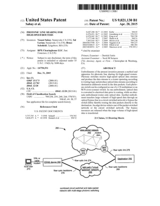
  • 1. (12) United States Patent USOO902113OB1 (10) Patent No.: US 9,021,130 B1 Sahay et al. (45) Date of Patent: Apr. 28, 2015 (54) PHOTONIC LINE SHARING FOR 5. R : 3. Streal . . . . . . . . . . . . . . . .$8.5- W reenberg et al. HIGH-SPEED ROUTERS 6,970,942 B1 * 1 1/2005 King et al. ......... TO9,238 7,177.544 B1* 2/2007 Wada et al. ..................... 398,51 (75) Inventors: Vasant Sahay, Sunnyvale, CA (US); Tal 7,493.410 B2 * 2/2009 Moore et al. ... TO9,238 Lavian, Sunnyvale, CA (US); Bruce 2004/0015590 A1* 1/2004 Nagami et al. . 709/227 2004/O184615 A1* 9,2004 Elliott et al. ....... ... 380/283 Schofield, Tyngsboro, MA (US) 2005/0030951 A1 2/2005 Maciocco et al. ......... 370,395.2 (73) Assignee: RPX Clearinghouse LLC, San * cited by examiner Francisco, CA (US) Primary Examiner— Derrick Ferris (*) Notice: Subject to any disclaimer, the term ofthis Assistant Examiner— Scott M Sciacca patent is extended or adjusted under 35 (74) Attorney, Agent, or Firm — Christopher & Weisberg, U.S.C. 154(b) by 3680 days. P.A. (21) Appl. No.: 10/750,531 (57) ABSTRACT 1-1. Embodiments ofthe present invention present a methodand (22) Filed: Dec. 31, 2003 apparatus for photonic line sharing for high-speed routers. (51) Int. Cl Photonic Switches receive high-speed optical data streams we and produce the data streams to a routeroperating accordingG06F 5/73 (2006.01) toroutinglogicandproduceoptical datastreamsaccordingtoH04L 2/70 (2013.01) H04L 2/28 (2006.01) destination addresses stored in the datapackets. Eachphoto (52) U.S. Cl nicSwitch canbeconfiguredas oneofa 1:N multiplexeroran AVe. we M:N cross-connect switch. In one embodiment, optical data CPC - - - - - - - - - - - - - - grgr. H04L 12/28 (2013.01) is converted to electrical data prior to routing, while an alter (58) Field ofClassification Search nate embodiment routes only optical data. Another embodi USPC .................. 709/238,239, 240,244; 370/351; ment transfers large Volumes ofhigh-speed data through an 398/45 49, 50, 57 opticalbypass lineinacircuitSwitched networktobypassthe Seeapplication file for complete search history. switch fabric thereby routing the data packets directly to the 56 Ref Cited destination.Anedgedeviceselects oneofthepacketSwitched (56) eferences Cite network or the circuit switched network. The bypass U.S. PATENT DOCUMENTS resources are released when the large Volume ofhigh-speed data is transferred. 5,757,795 A * 5/1998 Schnell ........................ 370,392 5,828.475 A * 10/1998 Bennett etal. .................. 398,52 21 Claims, 11 Drawing Sheets 260 N data packet network 262 routers fiberoptic link 278 Oer OOC EDGE device 268 p local user fiber optic backbone 270 fiber optic backbone 276 light path ("circuit Switched" network) 266 combined circuitswitched and data packet networkwith multi-stage photonic switching
  • 2. US 9,021,130 B1Sheet 1 of 11Apr. 28, 2015U.S. Patent
  • 3. US 9,021,130 B1Sheet 2 of 11Apr. 28, 2015U.S. Patent 99JanuasKuepuoO3S up!MS oluo)Oud 0/ íp-,,,,,,)
  • 4. US 9,021,130 B1Sheet 3 of 11Apr. 28, 2015U.S. Patent u0)MS oluo)Oud N-O-W
  • 5. US 9,021,130 B1Sheet 4 of 11Apr. 28, 2015U.S. Patent up MS oluoloud indino 96quod 88 OMS ouOOud indu Seu]]
  • 6. US 9,021,130 B1Sheet 5 of 11Apr. 28, 2015U.S. Patent
  • 7. US 9,021,130 B1Sheet 6 of 11Apr. 28, 2015U.S. Patent
  • 8. US 9,021,130 B1Sheet 7 of 11Apr. 28, 2015U.S. Patent
  • 9. US 9,021,130 B1Sheet 8 of 11Apr. 28, 2015U.S. Patent uol?SOd10160||
  • 10. US 9,021,130 B1Sheet 9 of 11Apr. 28, 2015U.S. Patent OZZ OOZ
  • 11. US 9,021,130 B1Sheet 10 of 11Apr. 28, 2015U.S. Patent uo. MS oluoroud indino uo. MS Ouoloud indu
  • 13. US 9,021,130 B1 1. PHOTONIC LINE SHARING FOR HIGH-SPEED ROUTERS BACKGROUND 1. Technical Field Thepresent invention relates to data packet networks and, more particularly, the presentinvention relates to high-speed routing ofdata packets in the data packet network. 2. Related Art Communication service providers, as well as networkSer Vice providers, face Some difficult challenges as the various networks are increasingly modified to work together to pro vide seamless end-to-end connectivity across the various platforms and protocols. Ever-increasing residential dial-up Subscribers and broadband Subscribers demand increasing network speed. To meet this demand, network service pro viders are deploying a large number of complex, port-dense NetworkAccess Servers (NAS) to handle thousands ofindi vidual dial-up connections. As such, Small and large, as well as privateandpublic, data packet networks arebeing created to enable users to establish point-to-point connections inde pendent of terminal type and location. Traditional circuit switched voice networks have paved the way forthe creation ofdata packet networks as users loaded the Voice networks trying to transmit data, including streaming data (video and voice). Initially, traditional Public Switched Telephone Net works (PSTNs) were used for data transmissions but have been largely supplanted by data packet networks, including various versions ofthe “Internet” forpurposes ofdata trans port. DuringtheInternetboom,fiberoptic cablewasinstalledto meettheincreasingdemand forhigh-speedaccess to the data packet network.With fiberopticcable,optical networkshave been developed in various forms utilizing various transport technologies. For example, dense wavelength division mul tiplexing (DWDM) is being used in optical networks to sig nificantly increase throughput and, more generally, to trans port data from point to point. High-speed transceivers up to OC-192 (OpticalCarrier,9.6 gigabits-per-second)havebeen installed to meet the increasing demand. The expectation beingthatthehigh cost ofinstalling and maintaining ahigh speed network will be recoveredas moreusers demand more bandwidth. The Internet business climate is changing and demands are being put on operators to provide bandwidth while optimizing the use of their networks to reduce the operating costs. Network operators and networkservicepro vidersthus needa moreeconomical methodtousetheexpen sive resources. Bandwidth is notonly a concern to individuals,butalso to service providers. From the operator's perspective, band width is the key to the number of users a communication system can Supportat any given time, theamount ofdatathat canbetransportedviathecommunicationsystematanygiven time, and the speed at which the data can be transported. Bandwidth thus translates intoa numberofpotential custom ers and revenue. Forthis reason, companies spend billions of dollars annually to develop equipment to increase the band width of communication systems, such as the Public SwitchedTelephoneNetwork(PSTN), wireless communica tion systems, wire line communication systems, and/or the Internet. One key standard that increases the bandwidth ofcommu nication systems, is SONET (Synchronous Optical NET work). SONET was created to provide a cost effective plat form for multi-vendor internetworking and offers the advantages ofback-to-back multiplexing, compatibility with 10 15 25 30 35 40 45 50 55 60 65 2 other standards, and ultra high performance. In particular, SONET is a transmission technology, which resides in the physicallayerandcanbeusedto carry awide varietyoftypes of traffic, including ATM (Asynchronous Transfer Mode) cells. In addition, theSONETphysicallayermaybeusedin a wide variety ofapplications, including LAN-to-LAN inter connections, host-to-host interconnections, video conferenc ing, team engineering, distributed processing, and advanced Scientific research. The basic building blocks of a SONET system are 125 microsecond frames that come in two sizes ofSynchronous Transport Signal (STS) frames: the STS-1 frame and the STS-3 frame. The STS-1 frame provides a bit rate of51.84 Mbps while the STS-3 frame provides a bit rate of 155.52 Mbps. Once an STS frame is converted from an electrical format into an optical format for transmission, the frame is then referred to as an Optical Carrier (OC), but still has the same bit rate as the STS frame. As mentioned, SONET is a transmission technology, which differs from switchingtechnology. Switchingtechnol ogy is concerned with how data is routedacross the network, whiletransmission technology is concerned with how datais encoded and transported across the network. SONET, there fore, separates the overheadofSwitchingtechnology, Such as ATMfrom thepayloadfields(i.e., thedata). As such,SONET is not applied directly to the Switching devices ofa network, but is used to specify the interfacebetween the switches that are linked by optical fibers. Thus, standard ATM or LAN switches are equipped with a SONET interface in order to comply with the SONET specification. As the demand for bandwidth escalates, various network elements are being made to receive and transmit optical data forincreasedperformance. Opticalequipmentandtransceiv ers, forusein networkelements suchas routers,however, are expensive. Because a router has many different ports, using an opticaltransceiverforeachportresultsinthe useofoptical technologyforrouters beingvery expensive. What is needed, therefore,isarouterwithopticaltransceiversthatiseconomi cally feasible. BRIEF SUMMARY OF THE INVENTION Themethodandapparatus ofthepresentinvention reduces thecostofoperatingand maintaininghigh-speedopticalfiber networks by using scaleablephotonic Switches to selectively couple fiber lines to a shared optical transceiver port and optical router. The photonic Switches share an optical trans ceiverinputoroutputwith multiple fiber lines thereby reduc ing the number ofoptical transceivers needed to service the multiple fiberlines. Unusedorlightly used fiberlines may be reduced through the use of photonic Switches to carry data packets. Moreover,dedicatedbackup fibermaybereducedas one backup fiber may be used to provide redundancy for multiple primary fibers. A routing system of the present invention comprises at least one high data rate input optical port that receives high datarateopticaldataandconvertstheopticaldatatoelectrical data,Switchfabriccoupledto receivetheelectrical dataandto switch the electrical data to route the electrical data on a packet-by-packet basis to an output optical port, and at least onephotonic Switch coupled to aplurality ofoptical ports.A plurality offiberlinesarecoupledtotheinputopticalportand optical outputportofthephotonic Switchto transmitthedata packetsfromasourcetoadestinationstoredinthedatapacket header. Switch intelligence comprising one ofa data packet rout ing system controllerandroutinglogicevaluatesthehighdata
  • 14. US 9,021,130 B1 3 rate optical data to determine an efficient transport mecha nism. The transfer ofa small volume ofdata may be routed through the datapacket network. The routinglogic maintains a mapping table foreach inputandoutputphotonic Switch to optimize the routing ofdata packets based on the destination IP address. The switch intelligence transmits control com mands to route the data packet through the input photonic Switch and the output optical Switch. In one embodiment, the optical data is converted to elec trical databefore routingthrough thedata packet network. In another embodiment the data packet stays in the optical domain duringthe routing and Switching process. Large data transfers are moreefficiently transportedthrough a dedicated optical path, or light path, using a mechanism similar to circuitSwitchinginwhichadedicatedend-to-endopticalpath is established from the source to the destination. In one embodiment ofthepresent invention, a large Volume ofdata is circuitSwitchedthroughan opticalbypass linetobypassthe packet Switched circuits to reducing loading on the data packet network. The above-referenced description of the Summary ofthe invention captures some, but not all, ofthe various aspects of the present invention. The claims are directed to some of the various other embodiments of the subject matter towards which the present invention is directed. In addition, other aspects, advantages and novel features ofthe invention will become apparent from the fol lowingdetailed description oftheinvention when considered in conjunction with the accompanying drawings. BRIEF DESCRIPTION OF THE SEVERAL VIEWS OF THE DRAWINGS FIG. 1 is a functional block diagram of a data packet network; FIGS.2Aand2Bshowadual redundantopticalconnection and one advantage ofphotonic line sharing accordingto one embodiment ofthe present invention, respectively; FIG. 3 illustrates line sharing with a photonic switch according to one embodiment ofthe present invention; FIG. 4 illustrates a routing system according to one embodiment ofthe present invention; FIG.5 illustratesadatapacketroutingsystem accordingto oneembodiment ofthe present invention: FIG. 6 is a functional block diagram that illustrates one aspect ofa data packet routing system controller, FIG. 7 illustrates a photonic switch mapping tableaccord ing to one embodiment ofthe present invention; FIG. 8 illustrates operation ofan optical binary switch; FIG. 9 isa flowchartfora methodofroutinga data packet in a high-speed routing system in one embodiment of the present invention; FIG.10illustratesamulti-stagephotonicSwitchingsystem according to one embodiment ofthe present invention; and FIG. 11 isaschematic blockdiagram ofacombinedcircuit Switched and data packet network with multi-stagephotonic Switchingaccordingto oneembodiment ofthepresentinven tion. DETAILED DESCRIPTION OF THE INVENTION FIG. 1 is a functional block diagram of a data packet network. Data packet network 10 comprises a number of networking elements interconnected to transmit and receive data packets. Shown are several regional Network Service Providers (NSP)connectedbyfiberopticbackbonestocreate a portion ofan interconnected data packet network, i.e., the Internet. Regional NSP 14, regional NSP 18, and regional 10 15 25 30 35 40 45 50 55 60 65 4 NSP 22 have high-speed routers (not shown) to route data packets between each network over a fiber optic backbone. Each router maintains a configuration table entry for every router with which itcan connect. Each ofthe routerentries in the configuration table describes a range of addresses con nected to each router. The router accesses the configuration table entry to determine if the router can forward the data packet to the destination. A local NSP 26 connects to regional NSP 14 through NetworkAccessPoint(NAP)30 toallownetworksubscribers to access the datapacket network. Local user34 connects to local NSP26 overa broadband connection includingeithera Digital SubscriberLine(DSL) ora cable modem.Abusiness Local Area Network(LAN)38 maintains a fiberoptic linkto local NSP26overa dedicated fiberoptic linkand also main tainsaT-1 (Trunk Level 1) line forbackup. Users ofbusiness LAN38andlocaluser34canseamlesslyconnecttoanyother entity in the data packet network using a variety ofnetwork ing protocols such as TCP/IP. Connected to regional NSP 22 through NAP 42, a service provider46 providesa numberofnetworkservices including nightly backup services and secure storage for confidential information. The distributed design of the data packet net workallows service provider46 to provide services to busi nesses, such as business LAN 38, though not directly con nected to the same network service provider or NAP. This aspectofthe distributed design ofthe data packet network is especiallydesirableformaintaining multipleremotebackups in case ofa tragic event such as a terroristattack. The present invention reduces the cost for network opera tors, such as serviceprovider46 and local NSP 26, by reduc ingthe costofoperating redundantand/orunused fiberoptic lines through photonic line sharing. High-speed routers for high-speedopticaldatarates(OC-192,etc.)aresharedamong lightly used fiber optic lines with sporadic heavy volume by Switching data packets through photonic Switchesbasedon a destination address. FIGS. 2Aand2Bshowadual redundantopticalconnection and one advantage of photonic line sharing, respectively, according to one embodiment of the present invention. As shown in FIG. 2A, a high-speed router 50 includes two 10 Gbps optical transceivers. Each opticaltransceiverSupports a linkto a serverwherein onelinkis an activeprimary linkand theotherisabackuporstandbylink.Aprimary link54carries data packet traffic between the high-speed router 50 and a primary server58,whileasecondstandby link 62isa standby link to a secondary server 66. In this configuration, standby link 62 and secondary server 66 are redundant backups to primary server58 and primary link54. Accordingly, the sec ond optical transceiveris not used unless there is a failure on theprimary servercircuit.Thecostofmaintainingthebackup system includes, therefore, an expensive 10 Gbps optical transceiverthat is only used for backup purposes. Increasing competition intoday's marketplace is driving networkopera tors to reduce costs. One method to reduce cost is to reduce the use of expensive optical transceivers that otherwise sit idle. FIG. 2B illustrates photonic line sharing according to one embodiment ofthe present invention. In the configuration of FIG. 2B, the backup optical transceiver has been removed. The primary optical transceiver is coupled to a photonic switch 70 that is further coupled to primary link 54 and to standby link62. Photonic switch70 functions to routeoptical data eitherto primary link54 ortostandby link62 depending ona photonic switch control. Photonic switch70 is much less expensivethana 10Gbps.Accordingly,the networkoperator has substantially reduced the cost to the server's operator for
  • 15. US 9,021,130 B1 5 Supporting the dual redundant system without seriously impairing the functionality ofthe system. One aspect ofthe present invention is to reduce costs by replacing expensive optical transceivers with inexpensive photonic switches. Photonic switches are switches that con duct light, or photons, instead of electrons. Using Small micro-mirrors or controllable opaque devices based on sili contechnology,thephotonicSwitchescreatelogicalonesand Zeros by turning light on and off. Electrical Switches are typically composed oftransistors and resistors and, as such, consume electricity and produce heat. Photonic Switches exhibit low power dissipation, low optical loss and, because of their Small size, offer a reduction in equipment space “footprint. Additionally, by switching light, the photonic Switch operates equally well with low and high data rates so that they are bit-rateindependent. Electrical switches exhibit Some high frequency loss and are bit-rate dependent and thereforeless desirable. Photonic switches can beconfigured as multiplexers or as digital cross-connect Switches to increase the port density ofhigh-speed routers in an optical network. Another method to reduce cost is to spread the cost of installing and maintaining optical fiber links across all the users ofthefiberlink. In theexampleofFIG. 2A, the server's operator is responsible for the cost of two dedicated fiber optic links, namely, primary link 54 and the unused standby link 62. By using theoptical transceiverand the standby link unused in other applications, the cost of maintaining the fiber-optic link is reduced. FIG. 3 illustrates line sharing with a photonic switch accordingto oneembodimentofthepresent invention. Inthis example, a photonic switch 74 is configured as an M-to-N photonic cross-connect Switch, where N is greaterthan M.A high-speed router 78 includes a plurality (M) of 10 Gbps optical transceiversoperably coupledtotheinput ofphotonic switch 74. Photonic switch 74 routes the data packets to network destinations (1, 2, ...N) in data packet network 10. In this configuration, each optical transceiver can route data packets to any network destination by the proper control of photonic switch 74. The routing and control ofthe photonic Switch will be described in relation to FIG. 4 and FIG. 5. Becausethephotonic Switch is less expensive to expandthan is adding optical transceivers, fewer optical transceivers are needed to Support the data packet routing through the photo nic Switchtothe datapacket network. In a normal datapacket flow, the routing ofdatapackets through thephotonic Switch will be transparent to most network users. FIG. 4 illustrates a routing system according to one embodiment of the present invention. A routing system 80 comprises an input photonic Switch 84, an input optical port 88, a switch fabric 92, an output optical port 96, an output photonic switch 100, and a controller 104. Input photonic switch 84 functions to switch optical data from ingoing fiber lines to input optical port 88 according to controlcommandsreceivedfromcontroller104. Inputoptical port 88 receives high data rateoptical data from input photo nic switch 84 and converts the optical data to electrical data using techniques known to one of average skill in the art. Switch fabric 92 routes the electrical data, as received from input optical port 88, on a packet-by-packet basis according to a destination address stored in the data packet headerand routing configuration rules. Similarly, output optical port96 receives electrical data and converts it to optical data. Con troller 104 includes computer instructions that define the routinglogicofroutingsystem80. Basedon ingoingfiberline conditions and outgoing fiber line conditions, controller 104 issues control commands to input photonic Switch 84 and 10 15 25 30 35 40 45 50 55 60 65 6 output photonic switch 100 to route the data packet to the destinationaddress containedinthedatapacketheaderbythe bestrouteavailable. Becauselineconditionschangeandrout ing elements can drop out ofservice, routing system 80 con tinuously updates the mapping table for the most efficient routingofdatapackets. As isknownto one ofaverage skill in the art, each data packet comprising the complete transmis sion may be routedby different paths through thedata packet network. Output photonic switch 100 is operably coupled to receive the control commands from controller 104 and to routethe optical datato theproper outgoing fiberlinesandto theproperdestination.Theoperation ofcontroller104willbe discussed in relation to FIG. 6. FIG.5illustratesadatapacketrouting system accordingto oneembodimentofthepresentinvention. Datapacketrouting system 110 comprisesan ingoing optical Switch module 114, a router 118, an outgoing optical Switch module 122, and a bypass and routing logic module 126. As may be seen, this embodiment includes theoptical switches as partofthe rout ing system. Ingoingoptical dataisreceivedoveraplurality of ingoingoptical fiberlinesand is coupledto a firstplurality of inputportstoingoingopticalSwitch module 114.Theingoing optical datais routedby ingoingoptical Switch module114to a first plurality ofinput ports according to commands issued frombypassand routinglogic module126. Router118directs the data packets to the data packet network according to a destination IPaddress stored in the datapacketheader.Addi tionally,router118routesdatapacketstoasecondpluralityof inputportstooutgoingopticalSwitchmodule122,whichthen routesthedatapacketsaccordingtoSwitchsettingscontrolled bybypassandroutinglogic module126.Theoutgoingoptical dataisfurthercoupledfromasecond pluralityofoutputports to outgoing fiber lines by control commands issued from bypass and routing logic module 126. Routing of normal data packets is accomplished by data packetrouting system 110asis knownbyone ofaverageskill in the art. Some applications require transferring of large Volumes of packet data. This large Volume of data places a load on the routing network beyond the design intent ofthe data packet network. More specifically, each data packet is typically 1.5 kilobits, thus an application transferring a large Volumeofdata, forexampleaone-gigabytefile,containsover 600,000 data packets. Each router in the routing path looks into each data packet header to make the next-hop decision. Theprocess is repeatedover 600,000 times for each routerin the routing path. One aspect of the present invention is to reducetheload on thepacket Switched networkby bypassing the data packet routingsystem (router118) for very largefile transfers (multi-gigabyte and multi-terabyte). Bypass and routinglogic 126 selects largefiletransfers forcircuitSwitch ingoveradedicatedend-to-endopticallightpath (bypass line 134) to reduce loading on the data packet routing system (router 118). As can be seen in FIG. 5, a client host 130 runningan externalapplication istransferringa large Volume of data through data packet routing system 110. In this example, routing logic module 126, in communication with clienthost130, switches the largevolumeofdataoverbypass line 134. The communication between client host 130 and bypass androutinglogic module126 maybeoveran Ethernet connection or a system signal line. Since router 118 will not be inspecting the data packets from client host 130, bypass and routing logic module 126 must receive a signal to start and stop bypass routing. Client host 130 may set bypass start-stop routing by time, application, provider, request, or forotherreasons. Forexample, routingbytimewouldaccom modate backup operations wherein a known Volume of data will be transferred in a known amount of time. Generally,
  • 16. US 9,021,130 B1 7 bypass routing involves routing the large Volumes of data from a number of known source addresses to a number of predefined destination addresses. Bypass and routing logic module 126 is shown as a component ofdata packet routing system 110. However, it may be designed external to data packet routing system 110. Such as a card in an optical rack controlling a plurality ofoptical Switch modules. Addition ally, bypass and routing logic module 126 may be formed in a controller comprising an Application Specific Integrated Circuit(ASIC)orFieldProgrammableGateArray (FPGA)as is known ofby one ofaverage skill in the art. FIG. 6 is a functional block diagram that illustrates one aspect ofa data packet routing system controller. Referring now to FIG. 6, data packet routing system controller 140 includesaprocessor144thatis coupledto communicateover abus 148.Abuscontroller152controls communications over bus 148. Memory 156 further is coupled to bus 148 and includescomputerinstructionsthatareretrievedbyprocessor 144 over bus 148 for execution. The computer instructions withinmemory 156definetheoperationallogicofdatapacket routing system controller 140. For example, memory 156 includes computer instructions that define the data packet routing system controller operational logic. Specifically, the computer instructions within memory 156 define routing logic for generating control commands to Switch each pho tonic Switch operably coupled to data packet routing system controller 140. More specifically, computer instructions within memory 156 define routing logic for mapping desti nation IP addresses to output port and photonic Switch posi tions based on the IP address within the data packet header. Bus controller 152 is furthercoupled to a communications port 160through which datapacket routing system controller 140 transmits control commands to the photonic Switches. Thus,whenprocessor144retrievesthecomputerinstructions stored within memory 156 and executes them to determine that it should generate control commands to the photonic Switches, processor 144 formats the signal and transmits it over bus 148 through bus controller 152 and out communi cations port 160 for transmission to the photonic switches. Data packet routing system controller 140 may be formed as a separate logic device or it may be formed internally withinthedatapacketroutingsystem. Further,thedatapacket routing system controller may be formed ofother technolo gies such as ASICs or FPGAs as is known to one ofaverage skill in the art. FIG. 7 illustrates a photonic switch mapping tableaccord ing to one embodiment ofthe present invention. The intelli gencecontrollingeach photonic Switch maintains a mapping table similarto the configuration table maintained by routers in the data packet network. The destination IP address, as defined in the data packetheader, ofeach datapacket routed throughthephotonic Switchisenteredintothe mappingtable. The input port switch information and output port switch information used in routing the data packet is stored in the switch andswitch position fields, respectively.The inputand outputportinformation is continuously updatedaccordingto known inputandoutputlineconditionssuchaslinetrafficand router status. The next two fields are variable length fields. The switch field contains anentry foreach switch used in the photonic switch. This allows for multiple input and output switches in a multi-stage switch. The switch position field contains an integer value for every entry in the switch field and represents the switch position of the respective switch used in routing the data packetthrough the photonic Switch. FIG. 8 illustrates operation ofan optical binary photonic switch. The photonic switch comprises a plurality ofswitch ing modules thatare usedto route input optical data received 10 15 25 30 35 40 45 50 55 60 65 8 atan input optical port to aselected output optical port. Each Switching module comprisesaplurality ofoptical Switchesto route thedatapacket. FIG. 8illustratesasimplebinaryswitch fordiscussionpurposes butis indicativeoftheoptical Switch ingofthephotonicSwitch.Continuingwiththedescription of FIG. 8, the binary switch has two states: ON or OFF. The binary switch comprises a movable mirror 170, a switching logic module174,a fixedmirror178, a focusinglens182,and an optical fiber 186 coupled to an optical output. ThebinarySwitchproducesalogic 1 oralogic0depending on the position ofmovable mirror 170 controlled by switch ing logic module 174. The input optical data, illustrated as light 190, strikes movable mirror 170 andis reflectedto fixed mirror178when movablemirror170isinthelogic 1 position. Light 190 is reflected by fixed mirror 178on to focusing lens 182 which concentrates light 190 on the input ofoptic fiber 186. To produce a logic 0, movable mirror 170 is positioned by switching logic module 174 to reflect light away from fixed mirror 178. In the logic 1 position the switch isON and in the logic 0 position the switch is OFF. Switching logic module 174controls theposition ofmovable mirror 170 as is known to one ofaverage skill in the art. Ina more complexSwitch Such as an opticalcross-connect switch,a movable mirrorreflects light to a selected mirrorof apluralityoffixedmirrors.Thelightreflectedfromeach fixed mirroris operably coupledto an optical output ortotheinput ofanother optical Switch. The coupling ofSuccessive layers ofopticalSwitchescreatesaphotonicSwitchthatcanfunction as 1 to N multiplexeroras an M to N cross-connect switch. FIG. 9 is a flowchart fora methodofroutinga data packet in a high-speed routing system in one embodiment of the present invention. The high-speed routing system, compris ing one or more ingoing photonic Switches and one or more outgoing photonic Switches, receives a high-speed data packetstream(step200),overa fiberline,ataphotonicswitch input port. Each data packet of the high-speed data packet stream includes an IP destination address in the data packet header, and the routing system evaluates the destination address (step 204) of each packet in the high-speed data packet stream. The routing system, based upon an external input,determinesa Switchposition ofafirstingoingphotonic Switch to select one ofaplurality ofinput light streams (step 208) that comprises the high-speed data packet stream. In a multi-stagephotonicSwitch,theinvention includesdetermin ing, based upon an external input, a Switch position of a second ingoing photonic Switch to select one oftheplurality ofinput light streams to the second ingoing photonic Switch (step 212). The external input is operably coupled from a Switch intelligence comprising one ofa routing logic and a data packet routing system controller. The operation ofthe data packet routing system controller was previously described in relation to FIG. 6. Thehigh-speedrouting system determines,based uponthe destination address, which output port should transmit the datapacketandforwardsthedatapackettothecorresponding output port (step 216). Based upon at least one ofthe desti nation address and a known output fiber line condition, the high-speed routing system determines a Switch position ofa first outgoing photonic Switch (step 220) and produces a control command to the first outgoing photonic Switch if necessary(step224).Thecondition oftheoutputfiberlines is updatedcontinuously and maintainedinthe mappingtableas previously described in relation to FIG. 7. The high-speed routingsystem uses this information to determinetherouting path through the ingoing and outgoing photonic Switches (step 228). This generally includes determining the switch positionforasecondoutgoingphotonic Switch,whichsecond
  • 17. US 9,021,130 B1 9 outgoing photonic Switch is coupled to the first outgoing photonic Switch and produce the control command to the second outgoing photonic Switch, if necessary, to cause the datapacketto becoupledtoacorrectfiberlineinoneembodi ment ofthe invention. FIG.10illustratesamulti-stagephotonicSwitchingsystem according to one embodiment ofthe present invention. This embodiment expands the number of fiber lines that are Switched, or cross-connected, from input to output. A single stagephotonic Switchingsystem, routing system 80 ofFIG. 4 for example, typically receives ingoing data packets over ingoingfiberlines connected to asingle NAP. Similarly, data packetsareroutedto an outputportforSwitching to outgoing fiber lines thatconnect to a singleNAP. Multi-stagephotonic Switchingsystem230incorporatesapluralityofingoingpho tonic Switches coupledto receivedatapackets overaplurality ofingoingfiberlines. Each ofthepluralityoftheingoingfiber lines connects to a different NAP. A plurality ofoutgoing photonic Switches is coupled to receive datapackets from an output photonic Switch. Each of the plurality of outgoing photonic switchesconnectstoadifferentNAPoveraplurality ofoutgoing fiber lines. A first ingoing photonic Switch 234 receives data packets from a first NAP (not shown) overa firstplurality ofingoing fiber lines. A second ingoing photonic switch 238 receives data packets from a second NAP (not shown) over a second plurality ofingoingfiberlines.Afirstselectedfiberlineofthe firstplurality ofingoingfiberlines is selectedby first ingoing photonic switch 234 and connected to a first input ofinput photonic Switch242accordingtocontrolcommands received fromSwitchingsystemcontroller246.Asecondselectedfiber lineofthesecondpluralityofingoingfiberlines isselectedby second ingoing photonic Switch 238and connected to a sec ond input ofinput photonic Switch 242 according to control commands received from Switching system controller 246. Routing ofdata packets from input photonic Switch 242, through the optical ports and Switch fabric, to an output photonic switch 250 is a functional equivalent to the opera tion of routing system 80 described with respect to FIG. 4. Continuing with the discussion of FIG. 10, data packets received by outputphotonic switch 250 are routed according to information storedin the mappingtable. Switchingsystem controller 246 switches the data packets received by output photonic switch 250 to one of a first or second outgoing photonic switchaccordingto the IPaddress storedin thedata packet header. The IP address specified in each data packet header determines which NAP can access the specified IP address. Switching system controller 246 transmits control commandsto eitherafirstoutgoingphotonic Switch254orto a second outgoing photonic Switch 258 to Switch the data packetto the correct outgoing fiber line ofthe outgoing fiber lines for routing to the specified NAP. FIG. 11 isaschematic blockdiagram ofacombinedcircuit Switched and data packet network with multi-stagephotonic Switchingaccordingto oneembodiment ofthepresentinven tion.ThecombinedcircuitSwitchedanddatapacketnetwork, showngenerally at260, comprises adatapacket network262 and a light path 266 (circuit switched network) operably coupled to fiberoptic linksbetween an edge device 268anda destination282.Accesstodatapacketnetwork262 is through NetworkAccess Point (NAP) 272 and NAP 284. Aplurality of routers 264 within data packet network 262 route data packets to destination 282 based on a destination address stored in the data packet header. Light path 266 comprises a plurality of dedicated end-to-end optical connections and photonic switches to efficiently switch data from fiber optic backbone 276 to fiber optic backbone 280. 10 15 25 30 35 40 45 50 55 60 65 10 A local user270 sendsa largevolumeofdata todestination 282. Edge device 268 is operably coupled to data packet network 262 (a packet switched network) and to light path 266 (a circuitswitched network)overfiberoptic link274and fiber optic backbone 276, respectively. Based on the size of the data transfer, edge device 268 selects one ofthe packet switched network or thecircuit switched network forthe data transfer. Data packet network 262 includes a plurality of routers264toswitchdatapacketsfromNetworkAccessPoint (NAP)272to NAP284. As is known tooneofaverageskillin theart, routers264switch datapacketsbetweenNAP272and NAP 284 based on a destination address stored in the data packetheader. Eachroutermaintainsa routingtableofopera tional routers available to receive data packets. Data packets are forwarded through the path of routers until they reach destination 282. Light path 266 is a circuit switched network ofdedicated end-to-end optical paths and photonic Switches operably coupled between fiber optic backbone 276 and fiber optic backbone280. When datais transferred fromlocaluser270 to destination 282 via lightpath 266,acircuitinlightpath 266 is establishedorswitchedbetweenfiberopticbackbone276and fiber optic backbone 280 by established signaling systems. Thisswitchedcircuitisadedicatedpathfrom edgedevice268 to destination 282 and is maintained until the data transfer is complete then the switched circuit is disconnected which releases the Switch resources. Edge device 268 selects either the data packet networkor the circuit switched network based on the most efficient method forthe data transfer. Large Volumes ofdata are typi cally transferred through circuit switched network 266 because ofthe dedicated connection between local user 270 and destination 282. A smaller size data transfer may be routed through data packet network 266. The invention disclosed herein is susceptible to various modifications and alternative forms. Specific embodiments thereforehavebeenshownbywayofexampleinthedrawings and detailed description. It should be understood, however, that the drawings and detailed description thereto are not intended to limit the invention to the particular form dis closed,but onthecontrary,theinvention is to coverall modi fications,equivalentsandalternatives falling withinthespirit and scope ofthe present invention as defined by the claims. Moreover,asoneofaverageskillintheartwillappreciate,the term “substantially” or “approximately, as may be used herein, provides an industry-accepted tolerance to its corre sponding term. Such an industry-accepted tolerance ranges from lessthan onepercenttotwentypercentand corresponds to, but is not limited to, component values, integrated circuit process variations,temperaturevariations,riseandfalltimes, and/or thermal noise. As one ofaverage skill in the art will further appreciate, the term “operably coupled, as may be used herein, includes direct coupling and indirect coupling via another component, element, circuit, or module where, for indirect coupling, the intervening component, element, circuit,ormoduledoes notmodifytheinformation ofasignal but may adjust its current level, Voltage level, and/or power level. As one ofaverage skill in the art will also appreciate, inferred coupling (i.e., where one element is coupled to another element by inference) includes direct and indirect couplingbetweentwoelements inthesame manneras "oper ably coupled'. As one ofaverage skill in the art will further appreciate, the term "compares favorably, as may be used herein, indicates that a comparison between two or more elements, items, signals, etc.,provides a desiredrelationship. Forexample,whenthedesiredrelationshipisthatsignal 1has a greater magnitude than signal 2, a favorable comparison
  • 18. US 9,021,130 B1 11 may be achieved when the magnitude ofsignal 1 is greater than that ofsignal 2 orwhenthe magnitude ofsignal 2 is less than that ofsignal 1. What is claimed is: 1.Amethodforroutingadatapacket,themethodcompris ing: receiving a data packet stream at a first ingoing photonic Switch; foreach datapacketofthedatapacketstream,evaluatinga destination address ofthe data packet; determining whether to bypass a router and transmit the data packet from the first ingoing photonic Switch to a first outgoing photonic Switch via a dedicated optical pathbasedon a volumeofpacketdata to be transferred; determining, based on an external input, a Switch position of the first ingoing photonic Switch to select one of a plurality ofinput light streams; determiningatthe first outgoingphotonicSwitch, to which one ofa plurality ofoutput ports the first ingoing pho tonic Switch should transmit the data packet and for warding the data packet to the corresponding output port; determiningatthe first outgoingphotonic Switch,a Switch positionofthefirstoutgoingphotonic Switchbasedonat least one ofthe destination address and aknown outgo ing fiber line condition; and producing a control command to the first outgoing photo nic Switch to prompt the first outgoing photonic Switch to conduct an outgoing optical data packet on a first Selected fiber corresponding to the control command. 2. The methodofclaim 1 furtherincluding, foreachpacket ofthe datapacketstream, determining a switch positionfora second outgoing photonic Switch, which second outgoing photonic Switch is coupled to the first outgoing photonic switch by the first selected fiber and producing a control commandtothesecondoutgoingphotonicSwitchtocausethe outgoing optical data packet to be conducted on a second selected fiber. 3. The method ofclaim 1 further including determining, based upon the external input, a Switch position of a first outgoing photonic Switch to select one ofaplurality ofinput light streams being conducted on one ofa first plurality of output fibers. 4. The method ofclaim 3 further including determining, based upon the external input, a Switch position ofa second outgoingphotonicSwitch to selectoneofaplurality ofoutput lightstreamsbeing conducted on one ofa second plurality of outputfibers coupledto thesecondoutgoingphotonicSwitch. 5. A routing system, comprising: at least one input photonic Switch coupled to at least one optical port, the at least one optical port receiving data packets carried on one of a plurality of ingoing fiber lines, the at least one input optical port configured to receive optical dataand convertthe optical datato elec trical data; at least one output photonic Switch coupled to at least one output optical port; a switch fabric configured to receive the electrical data from the input optical port and to switch the electrical data to route the electrical data on a packet-by-packet basis to at least one output optical port; and foreach photonic switch, a plurality offiber lines coupled to the photonic switch; ifthephotonic Switch is coupledto an inputopticalport, the input optical port is configured to receive data packets carried on one ofa plurality ofingoing fiber lines; and 5 10 15 25 30 35 40 45 50 55 60 65 12 if the photonic Switch is coupled to an output optical port, the output optical port is configured to transmit data packets to the photonic Switch to be carried on one ofa plurality ofoutgoing fiber lines; and theroutingsystem beingconfiguredto determine,basedon an external input, a Switch position of the first input photonic Switch to selectone ofaplurality ofinputlight streams, the routing system being further configured to determine whether to bypass a router and transmit a plurality of packets through a dedicated optical path based on a volume ofpacket data to be transferred. 6. The routing system ofclaim 5 wherein the routing sys tem comprises routing logic configured to produce control commandsto each photonic Switch coupled totheinput opti cal port to select at least one ofthe plurality ofingoing fiber lines and to produce control commands to each photonic Switch coupledto theoutput opticalportto selectatleast one ofthe plurality ofoutgoing fiber lines. 7. The routing system ofclaim 6 further comprising a data packet routing system controller wherein the routing logic is defined in computerinstructions executed by the data packet routing system controller. 8. The routing system ofclaim 6 furtherincluding routing logic configured to: map destination IP addresses to output optical ports and photonic Switch positions; evaluate a destination IP address within a data packet header and, based upon the mapped output optical port and Switch position information: route the corresponding data packet to the mapped out put optical port; and produce a control command to the photonic switch to prompt the photonic Switch; and conduct the data packet to the selected outgoing fiber line. 9. The routing system ofclaim 6 further including routing logic configured to: map destination IPaddressestotheoutputopticalportsand photonic Switch positions; evaluate a destination IP address within a data packet header and, based upon the mapped output optical port and Switch position information as well as known out going fiber line conditions: route the corresponding data packet to the mapped out put optical port; and produce a control command to a photonic Switch coupled to the mapped output optical port to prompt the photonic Switch to conduct the data packet to the selected outgoing fiberline. 10. The routing system of claim 6 wherein the outgoing fiber line is selected according to a destination address on a packet-by-packet basis. 11. The routing system of claim 6 wherein the outgoing fiberline is selectedaccordingto the destinationaddress on a packet-by-packet basis based upon a destination address defined within a data packet header. 12. The routing system of claim 6 wherein the outgoing fiberline is selected according to aknown output line condi tion. 13.Therouting system ofclaim 6 wherein an ingoingfiber line is selected according to a known input line condition. 14. A datapacket routing system, comprising: an ingoing optical Switch modulehavingafirstplurality of input ports coupled to a plurality offiber lines carrying ingoing optical data, the ingoing optical Switch module configured to conduct optical data to one of a second plurality ofoutputports;
  • 19. US 9,021,130 B1 13 anoutgoingopticalswitchmodulehavingasecond plural ity of input ports coupled to a plurality of fiber lines carrying outgoing optical data, the outgoing optical Switch moduleconfiguredtoconductoptical datato one ofa first plurality ofoutput ports: a routing system coupled to at least one fiber line of the Second plurality of output ports ofthe ingoing optical Switch moduleandcoupled to least one fiber line ofthe Second plurality of input ports ofthe outgoing optical Switch module; at least one fiber line configured to couple the ingoing optical Switch module to the outgoing optical switch module to create an optical bypass line; and bypass and routing logic comprising a processor and memory configured to: determine whether optical data is to be conducted throughtheroutingsystem orwhethertheopticaldata is to bypass the routing system and be conducted through the optical bypass line based on a volume of packet data to be transferred; and determine, basedonanexternal input,a switch position ofthefirstingoingoptical switch moduletoselectone ofa plurality ofingoing optical data streams carried on the plurality offiber lines. 15.Thedatapacketroutingsystem ofclaim 14 wherein the bypassandroutinglogicoftheroutingsystemisconfiguredto determinewhetherdataistobeconductedthroughtherouting System orwhetherthe routing system is to be bypassed on a data packet session basis. 16.Thedatapacketroutingsystem ofclaim 15 wherein the bypassandroutinglogicoftheroutingsystemisconfiguredto communicatewithanexternalapplication withinaclienthost to determine whetherto bypass a router. 17.The datapacketroutingsystem ofclaim 16 wherein the bypassandroutinglogicoftheroutingsystemisconfiguredto communicate with the external application within the client hostto determinewhentostopbypassingthe routingsystem. 18.Thedatapacketroutingsystem ofclaim 14 wherein the bypassandroutinglogicoftheroutingsystemisconfiguredto determinewhetherdataistobeconductedthroughtherouting System orwhetherthe routing system is to be bypassed on a packet-by-packetbasis. 10 15 25 30 35 40 14 19.Thedatapacketroutingsystemofclaim 14wherein the bypassand routing logic is external to the routing system. 20.Thedatapacketroutingsystemofclaim 14wherein the bypass and routing logic is configuredto bypass the routing System to cause the ingoing optical data to be transmitted directly to a specified output port. 21.Amethod forconductingtrafficthrougha network, the method comprising: receiving,atafirstphotonic Switch,data packets fortrans mission through an optical medium; determining whether to bypass a router and transmit the datapacketsthrough a dedicatedopticalpathbased on a volume ofpacket data to be transferred; and determining, based onan external input, a switch position ofthefirstphotonicswitchtoselectoneofaplurality of input light streams: if the data packets are to be transmitted though the data packet network: conducting the datapackets in an optical form towarda first optical port; and producing a control command to the first photonic Switch to conduct the data packets in anoptical form toapacketnetworkrouterfordeliverytoadestination by way ofa plurality of routers of the data packet network; and ifthe datapackets are to be transmitted through thededi cated optical path: determining to conduct the data packets in an optical form through a circuit switched network: producingthe data packets in the optical form to a sec ond optical port; and producing a control command to the first photonic switchto routethedata packets intheoptical form to a circuit switched network for delivery to a destina tion by way ofthededicated opticalpath; and themethodbeingperformedwithinanedgedeviceinclud ingthefirstphotonic Switch fordirectingthe datapack ets in the optical form in one ofa plurality ofoptical media for conducting optical data.