Radar target detection system for autonomous vehicles with ultra-low phase noise frequency synthesizer
•
0 likes•77 views

This patent application describes an object detection system using radar for autonomous vehicles. It includes an ultra-low phase noise frequency synthesizer to improve radar performance for target detection and characterization. The frequency synthesizer utilizes various components like a clocking device and phase-locked loops to reduce phase noise in returned radio signals, enabling better radar system performance.

Recommended
Recommended
More Related Content
Similar to Radar target detection system for autonomous vehicles with ultra-low phase noise frequency synthesizer
Similar to Radar target detection system for autonomous vehicles with ultra-low phase noise frequency synthesizer (20)
More from Tal Lavian Ph.D.
More from Tal Lavian Ph.D. (20)
Recently uploaded
Recently uploaded (9)
Radar target detection system for autonomous vehicles with ultra-low phase noise frequency synthesizer
- 1. THETWOTORTDITUNONTONULLAM MAULITINUS 20180019755A1 (19)United States (12) Patent Application Publication (10) Pub.No.:US2018/0019755 A1Josefsberg et al. (43) Pub.Date: Jan. 18, 2018 (54) RADAR TARGET DETECTION SYSTEM FOR AUTONOMOUS VEHICLES WITH ULTRA -LOW PHASE NOISE FREQUENCY SYNTHESIZER (71) Applicants: Yekutiel Josefsberg,Netanya (IL ); Tal Lavian, Sunnyvale,CA (US) HO3L 7/113 (2006 .01) HO3L 7/099 (2006.01) HO3L 7/24 (2006.01) HO3L 7/20 (2006.01) (52) U.S.CI.CPC ................ HO3L 77085 (2013.01); HO3L 7/24 (2013.01); HO3L 7/23 (2013.01); HOZL 7/20 (2013.01); HOZL 7/07 (2013.01); HOZL 7/113 (2013.01); HOBL 7/099 (2013.01); HO3L 7/185 (2013.01) (72) Inventors: Yekutiel Josefsberg,Netanya (IL ); Tal Lavian, Sunnyvale, CA (US) (57) ABSTRACT(21) Appl. No.:15/670,081 (22) Filed: Aug.7, 2017 Related U.S.Application Data (63) Continuation-in -part of application No. 15/379,860, filed on Dec. 15, 2016, now Pat. No. 9,762,251, which is a continuation of application No. 15/229, 915, filed on Aug. 5, 2016, now Pat.No. 9,705,511. (60) Provisional application No.62/181,221, filed on Jun. 18, 2015. An object detection system for autonomous vehicle, com prising a radar unit and at least one ultra -low phase noise frequency synthesizer, is provided. The radar unit configured for detecting the presence and characteristics ofoneormore objects in various directions. The radar unitmay include a transmitter for transmitting at least one radio signal; and a receiver for receiving the at least one radio signal returned from the one or more objects. The ultra -low phase noise frequency synthesizer may utilize Clocking device, Sam pling Reference PLL,atleast one fixed frequency divider, DDS andmain PLL to reduce phase noise from the returned radio signal. This proposed system overcomes deficiencies of current generation state of the art Radar Systems by providing much lower level of phase noise which would resultin improved performance ofthe radarsystem in terms of target detection, characterization etc. Further, a method for autonomous vehicle is also disclosed. Publication Classification (51) Int. Cl. HO3L 77085 HOBL 7/23 HOZL 7/185 HO3L 7/07 (2006 .01) (2006.01) (2006 .01) (2006.01) 2000 ** w wwwwwwwwwwwww *** wwww 00000000PHASENOISE(OBCH2) wwwwwwwwwww wwwwww2002 WM wwwwwwwwwwww 2006 i 2008 2010 w 20122012 FREQUENCYOFFSET{M }.me 2004
- 2. Patent Application Publication Jan.18,2018 Sheet 1 of 40 _ US2018/0019755 A1 + EA55 ????????? ? :??:54::+ ???? ?????????? FG.? ? ????? ???4}, ???a ??? - ? - - - ?????? XemN??t
- 3. *** PatentApplication Publication 202 204 206 208 TAXMWIW8716X477KW014 ??? . SA Ny Fout Fclock ReferenceClock MaKenRTROUX Loop Phasedetector wwwmua MINT WEHRKY VCO van 1 . WAWA . . PUMA FclockFout/N Jan.18, 2018 Sheet 2 of 40 WHWAY Divider* ** A97759717 W W94149494949940*40 994979744479 210. WWMWASOM CON10 WWW 400 ot.. FIG.2 US 2018/0019755 A1
- 4. PatentApplication Publication Jan.18, 2018 Sheet 3 of 40 US 2018/0019755 A1 US HYYYYYYYYYYTYMIANATAYMIYYAMNIPIVOTAVE Araw 304 MWYAYAYYYYY PFD FIG.3 NYAWKYAWN wanawe WYKRYYYTTFclock FoutN 300
- 5. PatentApplication Publication Jan.18, 2018 Sheet 4 of 40 US 2018/0019755 A1 TATAYOUT AS: KAW ** WWW bat 1 C2 WALIH ARAYAKAN TTTTITTEIT. FIG.4 26.7nF e NY 8 XXX 989R2PEMIUMae C AHWINFALASIAALKER KLASSIKALAPAKSARAI HAR
- 6. PatentApplication Publication Jan.18, 2018 Sheet 5 of 40 US 2018/0019755 A1 OUTPUT © podreu KWWWXUACH SAMPLESAMPLECONTROLpor 14W*WWWWWW Cassie OUTPUTINPUT FIG.5 WXWWVXwwwwwww W 502 CH como WWWWWWWWA SAMPLEV tem *** * **** * *** * * SAMPLECONTROLINPUT W
- 7. US2018/0019755 A1 FIG.6T WAAR ROWWE WOWAUWA se minadopara H Jan. 18,2018 Sheet 6 of40 2X1XXIT wwwmomme YTTET TITTATYTASTRTTITY 606 *7***RYMYINT 4 * * * VOLTAGEERROR IndNIA IndNIZHW001 602RF 4 604 Rezewa msex - VYVRYTATTATRYWISTMYR IT.Writi . Witvin ii.iii Yohanna Patent Application Publication
- 8. Patent Application Publication Jan. 18,2018 Sheet 7 of40 US2018/0019755 A1 I dem ana ? R VATAN wwwyobra power wwwwwwwwwwwI tertimerb obatahoto liningfinns enlinjanawasiwasiAOOUUU waffrirejiminingwawananchi erfinan tw ** m m miss AVAVwwe - inif on FIG.7 www ? notasto bemelerini en paperdelingerieinsectet adipiscinginsessa moveme ntinstant magambar memang within 9 VA wenginewengiwanafananasuwan
- 9. Patent Application Publication Jan. 18, 2018 Sheet 8 of 40 US2018/0019755A1 ? ??? 802 ???????????LANEKAWAITArcGREE MATESTINOHAMATESAAMre FIG.8 PARTS 800
- 10. US 2018/0019755 A1 FIG.9 Due w PARA S OSIONseudOVADedeus : WWWXXXXXX *** A MissaTeatr Jan.18, 2018 Sheet 9 of 40 m24 iff? *toit ?**startet 904 atatatan OSION Oseud Sa SSIONOudOomDugouny2013 ************** 006 PatentApplication Publication
- 11. US 2018/0019755 A1 Sepet1000 troyouder 1006 * * * ** Lorin as Noise a nimwamwanammmmmmm s Jan. 18, 2018 Sheet 10 of 40 > titut 654*** * * Noisa Xoder OlsetFrequency (Hx) FIG . 10 1008 * * 1004 OftsetFrequency (Hz . Mensured * ** * * * * * ***** WXX ******www SEX wwwwwwwwwwww.seguemingwinangun * *** ** * * *** * 1002 ** **** * * * *** W VO $ $ $ SOO feedspurspaprsque Patent Application Publication W090Aguanton SGSON$84d
- 12. US 2018/0019755 A1 FIG.11 N>N, oseyowasaNAS ( NONOOZ Jan. 18, 2018 Sheet 11 of40 W AMA 2 170W 090wo 090 1104 o 1102 **?! pbuyeodosON*080Osopueden 104 OOLL Patent Application Publication
- 13. US 2018/0019755 A1 FIG.12 29 3266666666666666666667 . M9HI *** ******** * **** Jan. 18, 2018 Sheet 12 of 40 cons 1200 Patent Application Publication
- 14. Patent Application Publication Jan. 18, 2018 Sheet 13 of 40 US 2018/0019755 A1 312 1304* **** ** 23939 ZOELINA09 wwwwwwwwwwwwwwwwwwwwwwwwwwwww1310 (20) 9??? FIG.13 1308 wwwwwwwwww wwwww*** 1314www 13181306 1300
- 15. Patent Application Publication Jan. 18,2018 Sheet14 of40 US2018/0019755 A1 SS S 14081410 ??SSS .... -- ? ???????????????????????????????????????????????????????????????????????? . 1406 FIG.14 ?1404 ?????? www.www 1400?
- 16. Patent Application Publication Jan. 18, 2018 Sheet 15 of 40 US 2018/0019755 A1 1504504 www BODNO 502 1508 FIG.15 w 1506 1500
- 17. ? * 3 ??1600 ????? ??? ??????? ? ?????????????????????????????? ::::::::::: : : : ?? ????????????? ?? ???? ???????? FIG.16? ?? ?? ???? ?? ? ?? ? ?? ? ??? ? ?? ? ?? ???? : ???????????????????????????????????????????? ? ? ?????????????: ?????????? ??? ? ?????? ?? ?? ??????????????? ?? ?? ????????????? ?? ?????????????????????????????????????????????????????... ? ???????? ????????? : : :: ??????????????? ? ? ????????????? *** * **** * ** ????????????????????????? Patent Application Publication Jan. 18,2018 Sheet 16 of40 US 2018/0019755 A1
- 18. US 2018/0019755 Al FIG.17 ? ' .. . . . .. ... . ..'. ??????????? 1722 1724 1718* * * *** * ** *** 1720 Jan. 18,2018 Sheet 17 of 40 * 1712? 1714 ??????? ? ? ?????????????????? 1716 173? - X8 ---- -- ? 1708 ? 1706 1704 1702 Patent Application Publicati0ll 1700
- 19. 1800 Patent Application Publication 1804 * * * ** ** ** * * * 1810 1802 1814 Synthesizer 1806 '.' . X8 1812 wwwwwwwwwwwwwwww 1816 **** Jan. 18, 2018 Sheet 18 of 40 * **1808 w SamplingValenceDas 1818 1822 1820SampingPL FIG.18 US 2018/0019755 A1
- 20. Patent Application Publication 1900 1916 19021904 f Tpg.. {4}} , ? -- X «12s3={ü.1.1 ????? {{ }{} ???? ??? 19081910 1906 1è12 * Jan. 18, 2018 Sheet 19 of 40 * » { ?!{... _ __ __ _ ___ __ _ _ ____ _____ __ __ __ _ _______ _ {??} 14 ??? 1918 {914 FIG.19 US 2018/001975Al
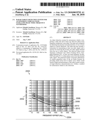
- 21. 2000 Patent Application Publication wwww Www * PHASENOISE(deck) gå&$*$8888 ** *** **** 2002 Www *** 2006 Jan. 18, 2018 Sheet 20 of 40 W 2008 2010.:2012 10 100 JOM 100M 1K0%100%IM FREQUENCYOFFSET(Mamma FIG.20 OEFSET(12)www.2004 US 2018/0019755 A1
- 22. US 2018/0019755 A1 707 'OI(24?????? (30) ????? ? * ::::;:::: 21: 3 9:33 :: ::::::::::. :::::::::::::: |;;::::::::.?*:..: ::: * **** :::::.: ?????:: 3;:;:: .:.:.:.:.:.:.;:: ::::::::::;:;:;??? wmodescriptionanasonanasoniconsorrenanasonrancointainesersionsensormanasonomineseason9:::::.:.{::::::::..:*:..::::::::: * ??? :::::::: :::::: : : **** ::: ::: 23:;..:::. |:: ::::.;;:: 32:::::::: ??? 25** ?? :::dev :.:. ? : ? . *** ? :;;; **** FE?.::: :: **.*:::::: .*:: ….. ::::::: : ? ? : :: ,:i:;; :::: ::: 1: ?::?. ** ? ?? ?? Jan. 18,2018 Sheet 21 of40 .3 | :: ::: : :::::: i:::: 32?????? : ::::.:::: ::::::: : ZOZ 07802807……907 ? E ;*.. ??? ?? :::::: : :: ...A$ 5-3.... :: ? 18:35.3.% ? ::::::::.::::::: is .::::: * 3 ***.: 2013;. : :::.:.:.:.:. ??*??:*:?*:.: :.:.:.:.:.:.... ????*?*.** .;::::::::::: ***.*****. ::::.;:::::::: **.*.*.*.* ::::.:.? .**** ::::...***** ? * * ? * : ::::?::: ::: :::;:; : ; :;::;: AMA : : ???? ?1 ?? : ??? ??????????? ?? ? : ::::: ?*:;.: 34S :.. :::.::?: ????ay Si:::::.:.::::.:.:.:.:.: :::::*:?:?:?:?:?:?:.i:. works.w .… :::::::::::::: :*::.:?*. . ? : $333322 Patent Application Publication 007
- 23. US 2018/0019755 Al 2Colg b02/ XIiero2848??}fx ??????? X20T Th?3 CH01 X( 1 - C?MC?ACHI1 , rarcrcrcfcrcrc *****:rcrcrcratorset ********** ? 28 ??? ???? ????????? ?????????? ?? ????????|?? ????????? ?????? : ?77 ??????. ? ?? ???:? ?????.?' :":? ? ?".:-??? {; ???? .. . . . ?? ?? ? ??? ?00+00 ? ? . ? ???? ? .:?????? ???? ??????????????? ? ????.? ????????????????????> ???????? ????.-?? C0/ ?80ZZ ..???? Jan. 18,2018 Sheet 22 of 40 ? ???????? ? ????? ?? ? ????? ???? ???????221??2 ? .. ..... .. ..… . . .. . ?9000 ? ? ????????????????? ???????????????????????? . ? ?????. ? ? ?? - ?. ?? ???????8 : 13:4 3 ???13 ? ??? ..? ? ???? ???. .?????? - - -- ?? **------ H ----,--- ??????? ??????????????????.?. + ??. i ???.? ??? 234 ? _ ? ??????? ???.????? .??????? g ? ? 8 8 --?? ? ??????????????????? ?.? ??????????????????????????????????????????? ????:????????????????????????.?.:??????;. ???????? ..???????????????? ????? :??????????????????::????????|.:. rwrm w *********ww mwwwwhi?www * * rm* * * * - * * ? * |? ** ** www ** #}}} Pf ?? ? X?|? ? ? A3% D9 % 8C% EN ? .| xxxdwn' 00Z2 Patent Application Publicati0ll
- 24. US 2018/0019755 A1 FIG.23 2304 svonbanW9001o WHO ON 29 1 * ** w 2312 VX8* Jan. 18, 2018 Sheet 23 of 40 23102308 * .. . ** ***** 2302 * ***NoiseABC ** ***************** ****** * ******** WWWWWWWW 2306.. . ** * *** . *XXX XX 2 8 .4 . 2 * ** * * ***.* **. 22.1. * *.*** wwwwwww . 600m ***** *********** * *** *** ***** *** *** * ***** w.. mo *:*::.. i * *** ** ***** * w * W ** *** wwwwwwwwwwwwwwwwwwwwwwwwwwwwwwwwwwwwwwwwwwwwwwwwwwww w www SIGNINGUOSONEY Patent Application Publication 2300
- 25. US 2018/0019755 A1 v0vZ t701 (ZH)Aguonbag |v0vZ?????????? ?? ?? ??? ??? ?????? ?? ? : ??????????????????????? :????????????????? ? ????????????????????? :::::::::::::::::::::::::: : ? ??????????????? ???:? ? ???????????????????????????? ???????????????????????? .. .... :: : . : : ::. ::: :: ::: :: ? ????????? ???????? .::::::::::....... ::????????????????????????????? ??????????.???????????????????????????????? .... . .. :: :::::::::: . ? ? .. .??? ?????? ???????????????????????????????????? ???:?? ???? ?? :: : . :. : : .. . ... :: : ::..::... ::::: " ??????????????? ????????? ???? ??? ?????? ?????????? ????? ?????? ?????????? ????????????????????????????????????? ?????????? ? ???????????.. ??? 3 . :: ::. : : : : : ???????047?????80EZ :::: : : : : ..::::: .:: :: : ::: : : .. . ??? ???????????? ??????????????? ? ???? ?? Jan. 18,2018 Sheet 24 of40 . . .. : : : :::: .. : :: ....: 3 70b7 ?? . ???::::::::: ????????????????.?????????????????????????????:????::::: ?????????? ????????????????????? ???? :::....??????:: ???????????????? ?????????? ????????????????????????????????????? ?????? ??::..::. ? ????????????????????????????????????????????? :: ::::::: ???????????????????????????????? . ???." . ???? 3 ? ???? :: :::: :: :: :: :: :::: :? . .??????????????????????????? ? ???:?? .. . . .. ?.? . ? : ?? :: . . . . .... : :: : : ::::: ????????? ??????????? ??????????????? ?????????????? ?????? : . :: : : : : ::: : .. :: :: ::: .. ... :: ... ???? ? ???? ?? ?? ?????? ??? ? ???? : : : : :::: : : : :::: ::::::::: :: ::: : ::::::::: :: ..:??!.??????????????????????? . . .. .. ...?? ???????????????????.??? ???? : ::: : ????????????????? ? ?.?? ' :: : . .. ' :: ? ::: : :'' ... :::: :: ::: . .. ::: :. .:: :: .:: : :.. .:::::::::: . ?????????????? ?????? ??? ?????????????? 4 443?? 0077 Patent Application Publication
- 26. Patent Application Publication Jan. 18, 2018 Sheet 25 of 40 US 2018/0019755 A1 9097 8097 OLG TLSL XHXX01 POSZ1890 0 . . . . . . . . . .. * * . . . * ... ::. :.. . . * * :.: .19 * * * ?????? * ** SjobeaucaSONY ??????????? ** XXXXXXXXXXX HiKuantan SZOLJ MWZW? ** Wwwm*WWWWWWWWWWW * MNTMAX001202X12M001** * * OOSZ 2097
- 27. US 2018/0019755 Al 90'5lg 6092 (&INA2%F%8923 ? ? ??? ? ??? ? ?? ? ff ??? ??? ??3 ??? ??????? .. ??????? ;?????? ? ???? ? ? ?????? ?.???????5 ?????????? ?????? ????????????????? ??????????? 89?????? 2092 -8A?? ????? 3?%0 ?? ????????????????????_ ?????????.??????.?? ? ??????? ? ??????????????????????? ? ? ? ?? ? ????? 2€XX? 0192 ? ? ?? ? ? ? ? ? ???? ? ???????;.;????? ????? ??????? ??'.'.? ??????.? ??? ? !??;£i .??????° ?.???????????????????4'|? ?? ???:; ????????? ?...? ???????????????? ???????? ?????? ? Jan. 18,2018 Sheet 26 of 40 ?????? ? /209 w? ??? ?? ? ??????????? ? ? ? ???????809 ?????????? ??? ? ? ??8 ???????? ??????..?? ????????????????. ?????????? ?:??| ? ?? ? ?????.;???? ??????? ? ???????????????? ?????????? ? ?????????? ? ??? ? 19}g 909/ ??????????????????? ????????? ?????? ?????????? :?: ?.??????? ?????????? ? ??????? ???????????????? ? ?? ???????????????????? ?? ? ?.'.??????????? i''.?????.:? ??????? ? ????;- .? .: .... . ... ??:..-*? ???????? ?????? ??????? ??????.. ???????? ??..???????????? ???????? ???? ????? ??3 fi ?? ? ? - ?????? ?? ?? ? ????????? ?????????... ? ?????????? ????????? ????????.?? ????? ?? 0;6? ??80????:Al ? ?? ?????|? .??????? ???????????????? .??? ? ?? ? ?? ???? ??.? ??.?? ' ?????????????????????????????? ??????. ????:?????????? ??? ? ??????? $ XXXQ ! ? ; ; $ $ ? ? ? i ? ? ? ? ??? 009/ Patent Application Publicati0ll
- 28. US 2018/0019755 A1 LZO13 SOUS LES SonorousOONKIDOGOO 90224Wako 4.4.4.4.4.484.8.8.4.484.8,8. 8.8.4.4, ,84244244344444444444444444 a cando oo W woo ********************************** wwwwwwwwwwwwwwwwwwwwwww wwwwwwwwwwwwwww Jan. 18, 2018 Sheet 27 of 40 ????? ??????? rrrrrr SAOpookySPRMOKKESPENNAsepantasmanosaresunt"Sco BogoW SONG So09de Powe MIOUCC 3osobaOdeesoseu PueoSOKNOW20224BIBERESOSOOSOOS DOLZ wwwwwwwwwwinningsu wwwwwwwwwwwwwwwwwwwwwwwwwwwwwwwwwwwwwwwwwwww Www wwwwwwwwww wwwwwwwwwwww ve WDUES 1 WA-SINGAPORESSOerunesus mo? Patent Application Publication DOLZ
- 29. Patent Application Publication Jan. 18, 2018 Sheet 28 of 40 US 2018/0019755 A1 -2804 S SAUSOSOLO FIG.28 9087 . . . . IIIIIIII . . . . . . . . . . . . . . CROSS.......... AL SILMLPlexe S 2802.. ........... SEX 2800 ? ? ? ?
- 30. US 2018/0019755 A1 FIG.29 Ensent . 4411.111.1- - 14-11411421411-4-UUL111.111LLLLLLLL14-L Sonvogelo362.0MOI DUOSalu@uosvorenpowyousoleselepVOL3XLOLJerseworksolentongBAONaseu&MO?enuwjoQeveralpuequ&tuquadanodu01770 GuidLesavantpappesi170erbov 9067- Jan. 18, 2018 Sheet 29 of 40 ????????????????????????????????????????????????????????????????????????????????????????????????????????? 1.12.2012 2222222222222222222222222222222222222222222222222 L2904 SjuosXoopOW01131uNosad.00SoubyopajuuaPuesacos2000???????????????????????????????? wwwwwwwwwwwwwwwwwwwwwwwwwwwwwwww 42-.647484 6:41.4411721-172-421431441121-14.11. 14 MHzto250MHZWnoisefrequencyresges100ATCX0gegenstosdocksignalsof Patent Application Publication Start 2900
- 31. Patent Application Publication Jan. 18, 2018 Sheet 30 of 40 US 2018/0019755 A1 *** ***** LIDAR"Deadzone" FIG.30A(PriorArt)
- 32. US 2018/0019755 A1 (Hyjoud)90€'913 im wwwwwww. 6666666666666666666666666666666666666666666666666*** W ************ * * ***** w ***** Jan. 18, 2018 Sheet 31 of 40 wwwwwwwwwwwwww wwwwwwwwwwwwwwwwwwwwwwwwwwwwwwwwwwwwwww: 14 ** www. Jeganogeundv017 Patent Application Publication
- 33. US 2018/0019755 A1 FIG.31(PriorArt) 2 reflectionsUnwanted ************ * *** ** * -:-V ******** ********** * Jan. 18, 2018 Sheet 32 of 40 ccide?*********** WeatherAdverse Peron1 *** ** ANN ***** * Patent Application Publication
- 34. Patent Application Publication ~10ftblind advancementat65mph ContinuousRadarContinuousRadar receive transmit Jan. 18, 2018 Sheet 33 of 40 FIG.32 (PriorArt) US 2018/0019755 A1
- 35. Patent Application Publication Jan. 18, 2018 Sheet 34 of 40 US 2018/0019755 A1 :25 23 RadarNotlimitedbylight1 X CameralimitedLightedArea Notvisiblefor CamerasFIG.33 Radarbehindplasticparts
- 36. Patent Application Publication Phasenoise"Skin" SlowmovingObject FastMovingObject ************1*14**444444444444444444********* Jan. 18, 2018 Sheet 35 of 40 FIG.34 (PriorArt) US 2018/0019755 A1
- 37. ;0.61 80= adu (PriorArt)FIG.35 wwwwwwwwwwwwwwwww jeudisuinjatcompressedPules .11111111111111111111 Sidelobes US 2018/0019755 A1Jan. 18, 2018 Sheet 36 of 40Patent Application Publication
- 38. Patent Application Publication Jan. 18, 2018 Sheet 37 of 40 US 2018/0019755 A1 sieulisyeamAqpanosgoS??? asouaseudIS adow{???4 ??? FIG.36 (PriorArt) ElevatedSNRaceydogandNoise
- 39. Patent Application Publication DetectingSystem 3702 3706 RadarUnit Memory 3710 3704 Instructionsset 3712 LowPhaseNoisefrequencysynthesizer Database Jan. 18, 2018 Sheet 38 of 40 3708 Processor 3700 FIG.37 US 2018/0019755 A1
- 40. Patent Application Publication Jan. 18, 2018 Sheet 39 of 40 US 2018/0019755 A1 3804 PM3802 .',' FIG.38 *** 3800
- 41. 3900 detectingapresenceofoneormoreobjectsinoneormoredirectionsbyaradarunit Patent Application Publication 3902 2 3904 Utilizingatleastoneultra-lowphasenoisefrequencysynthesizerforrefiningtransmittedandreceivedradarsignalsoftheradarunit 3906 Processingtherefinedreceivedradarsignalstodetermineoneormorecharacteristicsoftheobjects Jan. 18, 2018 Sheet 40 of 40 3908 2 Enableautonomousvehicletoadoptoneormoreactions basedonthedeterminedcharacteristicsoftheobjects FIG.39 US 2018/0019755 A1
- 42. US 2018/0019755 A1 Jan. 18, 2018 Sensor Technologies:RADAR TARGET DETECTION SYSTEM FOR AUTONOMOUS VEHICLES WITH ULTRA -LOW PHASE NOISE FREQUENCY SYNTHESIZER CROSS-REFERENCE TO RELATED APPLICATIONS [0001] This application is a continuation-in -part of U .S. application Ser.No. 15/379,860 filed on Dec. 15, 2016 , U .S. application Ser.No. 15/379,915 filed on Dec. 15, 2016 and International PCT application PCT/IB2016 /054790 filed on Aug. 9, 2016 is a continuation of U .S . application Ser.No. 15/229,915 filed on Aug. 5, 2016, now U .S. Pat. No. 9 ,705,511, which claims priority to U .S .Provisional Patent Application No. 62/181,221 filed on Jun. 18, 2015, the disclosure ofwhich is hereby incorporated by reference in its entirety. [0002] This patent application relates to the co pending U .S. application Ser.No. 151640,904 that are incorporated by reference in its entirety. FIELD [0003] Embodiments ofthepresent disclosure are gener ally related to sensors for autonomous vehicles (for example,Self-Driving Cars) and in particularto systemsthat provide ultra-low phase noise frequency generation for Radar Application for autonomous vehicles. [0011] Simple cars and other types of vehicles are oper ated by humans and these humans rely on their senses such as sightand sound to understand their environment and use their cognitive capabilities to make decisions according to these inputs. For autonomous cars and other autonomous vehicles, thehuman sensesmustbe replaced with electronic sensors and the cognitive capabilities by electronic comput ing power. The most common sensor technologies are as follows: [0012] LIDAR (Light Detection and Ranging)- [0013] is a technology thatmeasures distanceby illumi nating its surroundings with laser light and receiving the reflections. However, themaximum power of the laser light needs to be kept limited to make them safe for eyes, as the laser light can easily be absorbed by eyes. Such LIDAR systemsare usually quite large, expensive and do notblend in wellwith theoverall design of a car/vehicle. Theweight of such systemscan be as high as tens ofkilogramsand the cost can be expensive and in some cases high up to $ 100, 000. [00141 Radar (Radio Detection and Ranging)— [0015] These days Radar systemscan be found as a single chip solution that is lightweight and cost effective. These systemswork very well regardless of lighting or weather conditions and have satisfying accuracy in determining the speed ofobjects around thevehicle.Having said the above, mainly because of phase uncertainties the resolution of Radar systems is usually notsufficient. 10016) Ultrasonic Sensors— [0017] These sensors use sound waves andmeasure their reflections from objects surrounding the vehicle. These sensors are very accurate and work in every type oflighting conditions. Ultrasonic sensors are also small and cheap and work well in almostanykind ofweather,but thatisbecause of their very short range of a few meters. [0018] Passive VisualSensing [0019] This type of sensing uses cameras and image recognition algorithms. This sensor technology has one advantage that none of the previous sensor technologies have colour and contrast recognition. As with any camera based systems, the performance of these systemsdegrades with bad lighting or adverse weather conditions. [0020] The table below is designed to provide a better understanding of the advantages and disadvantages of the differentcurrentsensor technologies and their overall con tribution to an autonomous vehicle: [0021] The following tables scores the different sensors on a scale of 1 to 3,where 3 is the best score: BACKGROUND Autonomous Cars: Levels ofAutonomous Cars: [0004] According to the Society ofAutomotive Engineers (SAE) cars and vehicles in general are classified into 5 different classifications: [0005] Level 0: Automated system hasno vehicle con trol, butmay issue warnings. 10006 ] Level 1: Drivermustbe ready to take control at any time. Automated system may include features such as Adaptive Cruise Control (ACC ), Parking Assistance with automated steering, and Lane Keeping Assistance (LKA) Type II in any combination. [0007] Level 2: The driver is obliged to detect objects and events and respond if the automated system fails to respond properly. The automated system executes accelerating, braking, and steering. The automated sys tem can deactivate immediately upon takeover by the driver. 10008] Level 3: Within known, limited environments (such as freeways), the driver can safely turn their attention away from driving tasks, but must still be prepared to take control when needed. [0009] Level 4: The automated system can control the vehicle in all but a few environments such as severe weather. The drivermust enable the automated system only when it is safe to do so . When enabled, driver attention is not required. [0010] Level 5: Other than setting the destination and starting the system ,no human intervention is required. The automatic system can drive to any location where it is legal to drive and make its own decisions. Item LIDAR RADAR Ultrasonic Camera Proximity Detection Range Resolution Operation in darkness Operation in light Operation in adverse Weather Identifies colour or contrast Speed measurement ANNWWNNE wwwwwwANN wwwwww ????????????????????| Size Cost Total 18 24 22 21
- 43. US 2018/0019755 A1 Jan. 18, 2018 [0022] The above presentation ofthe state of the tech nology proved a high-level view ofthe advantages and disadvantages of the technologies from different per spectives. Drawbacks of Current Sensors: [0023] As shown in the table above,the available sensors for existing autonomousvehicles areLIDAR, Sonar,passive vision (cameras), and radar. Many of these sensors come with significant drawbacks, while radar systems do not experience most of the drawbacks and thus better among other sensors,based on the table shown above: [0024] For example, LIDAR systemshave a “ dead zone” in their immediate surroundings (as shown in FIG . 30A ), while a Radar system will be able to cover the immediate surroundings of a vehicle as well as long range with enhanced accuracy. [0025] In order to eliminate the “dead zone” asmuch as possible LIDARs are mounted tall above the vehicle (as shown in FIG . 30B ). These limits the options of using parking garages, causes difficulty in the use of roof top accessories and finally also makes the vehicle less market able since such a tower does not blend in well with the design of a vehicle. [0026 Typical LIDAR systems generate enormous amounts of data which require expensive and complicated computation capabilities,while Radar systemsgenerateonly a fraction of this data and reduce the cost and complication ofon board computation systemssignificantly.For example, some types of LIDAR systemsgenerate amounts of 1-Gb/s data that require substantial amount of computation by strong computers to process such high mount of data. In somecases, thesemassive computationsrequire additional computation and correlation of information from other sen sors and sources of information. In some cases, the source for additional computations is based on detailed road infor mation collected over time in databases or in enhanced maps. Computations and correlations can be performed against past information and data collected over time. [0027] Typical LIDAR systems are sensitive to adverse weather such as rain , fog and snow while Radar sensors are not. A radar system willstay reliable and accurate in adverse weather conditions (as shown in FIG . 31). LIDAR systems use mechanical rotation mechanisms thatare prone to fail ure,Radars are solid state and do nothavemovingparts and as such have a minimal rate of failures. [0028] TypicalLIDAR systemsrely on a rotation speed of around 5-15 Hz. This means that if a vehicle moves at a speed of 65 mph, the distance the vehicle travels between “ looks" is about 10 ft. Radar sensor systems are able to continuously scan their surroundings especially when these systems use one transmitting and one receiving antenna (Bistatic system ) (as depicted in FIG . 32). Further,LIDAR systemsare not accurate in determining speed and autono mous vehicles rely on Radar for accurate speed detection. 10029 ] Sonar: (0030) Sonar sensors are very accurate ,but can cover only the immediate surroundings of a vehicle , their range is limited to severalmeters only. The Radar system disclosed in this patent is capable of covering these immediate sur roundings aswell and with similar accuracy. Further, Sonar sensors cannotbe hidden behind cars ' plastic parts which poses a design problem , Radars can easily be hidden behind these parts withoutbeing noticed. [0031] Passive Visual Sensing (Cameras): [0032] Passive visual sensing uses the available light to determine the surroundings of an autonomous vehicle . In poor lighting condition the performance of passive visual sensing systems degrades significantly and is many times depending on the light that the vehicle itself provides and as such does notprovideany benefit over thehuman eye.Radar systems, on the other hand, are completely agnostic to lighting conditions and perform the sameregardlessof light (as shown in FIG . 33). [0033) Passive visual sensing is very limited in adverse weather conditions such as heavy rain, fog or snow ; Radar systemsaremuchmore capable ofhandling these situations. Passive visual systemscreate great amounts ofdata aswell which needs to be handled in real time and thus require expensive and complicated computation capabilities, while Radar systemscreate much lessdata that is easierto handle. Passive visual systems cannot see " through ” objects while Radar can, which is useful in determining if there are hazardsbehind vegetation for instance such as wildlife that is aboutto cross the road. 10034]. Further, it is easily understandable that in order to cover all possible scenarios all (ormost of these sensors need to work together as a well-tuned orchestra.But even if that is the case,underadverse lightingandweather condition some sensor types suffer from performance degradation while the Radar performance stays practically stable under all of these conditions. The practical conclusion isthatRadar performance isnotdriven by environmental factors asmuch as by its own technology deficiencies, or a specific defi ciency of one of its internal components that the invention herewill solve. [0035 ]. Summarizing all of the advantages and disadvan tages mentioned above it is clear that Radar systems are efficient in termsofcost,weight, sizeand computing power. Radar systems are also very reliable under adverse weather conditionsand allpossible lighting scenarios. Further, SAR Radar Systems may be implemented to create a detailed picture of the surroundings and even distinguish between different types ofmaterial. [0036 However, the drawback of existing Radar sensors was the impacton their accuracy due to the phase noise of its frequency source, the synthesizer. Thus, an enhanced system is required for purposes such as for autonomous vehicles) that may utilize benefits of Radar system by mitigating/eliminating the corresponding existing draw backs. For example, the required enhanced system , in addi tion to improving common existing Radar systems, should also improve bistatic or multistatic Radar designs that use the same platform or different platforms to transmit and receive for reducing the phase ambiguity that is created by the distance of the transmitting antenna from the receiving antenna by a significant amount. [0037] Essentially,a signal that is sentout to cover objects (here: Radar Signal) is not completely spectrally clean but sent out accompanied by phasenoise in the shapeof“skirt” in the frequency domain, and will meet similar one in the receiver signalprocessing once it is received back. In a very basic targetdetection systems, fastmovingobjects willshift the frequency to far enough distance from the carrier so that the weak signal that is being received will be outside of this phase noise "skirt” . Slow moving objects,however, such as cars, pedestrians, bicycles, animals, etc. might create a received signal that is closer to the carrier and weaker than
- 44. US 2018/0019755 A1 Jan. 18, 2018 sound/radiation source, v is the velocity ofthe soundsource relative to the receiver and f is the frequency shift that is being created . After simplifying the equation, wewill get: Af=2.fo thephase noise and this signalwillbeburied underthisnoise and practically willbe non-detectable or non-recognizable. [0038] More advanced systems use modulated signals (such as FMCW ) but the same challenge to identify slow moving objects remains. The determination of two physi cally close objects Vs. one larger object is also being challenged by phase noise. [0039] Another advanced RadarSystem worth mentioning is Synthetic aperture Radar (orSAR ) that is described in a different section of this disclosure. [0040] Many algorithms andmethods have been devel oped to filter out inaccuracies of Radar based imaging, detection and other result processing. Some aremore com putational intensive while others are not. The common to all of them is that they are not able to filter out the inherent phase noise of the Radar system itself. 10041] This is crucialsince a lotofthe information a Radar system relies on, is in the phase ofthe returning signal. One simple example for this phenomenon is when a Radar signal hits a wall that is perpendicular to the ground or a wall that has an angle that is not 90 degree relative to the surface, the phases ofthe return signalswillbeslightly differentand this information could be “buried” under the phase noise of the Radar system . [0042]. Further, speckle noise is a phenomenon where a received Radar signal includes "granular” noise. Basically, these granular dots are created by the sum ofall information thatis scattered back from within a “resolution cell” .All of these signals can add up constructively, destructively or cancel each other out. Elaborate filters and methods have been developed,butall of them functionbetter and with less effort when the signals have a better spectral purity, or in other words better phase noise. One of these methods, just as an example, is the“multiple look” method.When imple menting this,each “look” happens from a slightly different point so thatthe backscatteralso looks a bit different. These backscatters are then averaged and used for the finalimag ing. The downsideofthis is that themore “ looks” are taken the more averaging happens and information is lost aswith any averaging. 10043] As additional background for this invention there are few phenomena that need to be laid outhere: [0044] Doppler Effect: [0045] The Doppler Effectis the change in frequency or wavelength of a wave for an observermoving relative to its source. This is true for sound waves, electromagnetic waves and any other periodic event.Mostpeople know about the Doppler Effectfrom their own experience when they hear a carthatis sounding a siren approaching,passing by and then receding. During the approach the sound waves get "pushed” to a higher frequency and thus the siren seems to have ahigherpitch,andwhen the vehicle gainsdistancethis pitch gets lowersince the sound frequency isbeing “pushed” to a lower frequency. [0046] The physical and mathematicalmodelof this phe nomena is described in the following formula: Where Av is the relativevelocity ofthesound source to the receiverand Afis the frequency shiftcreated by the velocity difference. It can easily be seen that when the velocity is positive (theobjects get closer to each other) the frequency shiftwillbe up.When the relative velocity is 0 , there will be no frequency shift at all, and when therelative velocity is negative (the objects gain a distance from one another) the frequency shift is down. [0047] In old fashioned Radars the Doppler effect gets a littlemore complicated since a Radar is sendingout a signal and expects to a receive signal that is lower in power but at the same frequency when it hits an object. If this object is moving, then this received signal will be subject to the Dopplereffect and in reality, the received signalwillnotbe received at the same frequency as the frequency of the transmit signal. The challenge here is that these frequency errors can be very subtle and could be obscured by the phase noise of the system (as shown in FIG . 34). The obvious drawback is that vital information about the velocity of an object gets lost only because of phase noise (see figure below ). The above is especially right when dealing with objects thatmove slower than airplanes and missiles,such as cars, bicycles, pedestrians, etc . [0048] Modulated Signals [0049] Newer Radar systems use modulated signals that are broadly called FMCW (Frequency Modulated Continu ouswave), but they can come in all forms and shapes such asNLCW , PMCW , chirps, etc. (Nonlinear Continuous Wave and Phase Modulated Continuous Wave). Themain reason forthe use ofmodulated signals is thatold fashioned Radars need to transmit a lot ofpower to receive and echo back from a target while modulated signals and smart receive tech niques can do that with much lower transmit power. [0050] Another big advantage of FMCW based Radar systems is that the distance of a target can be calculated based on Af from the instantaneous carrier signal rather than travel time.However, herein also lies the problem — to be able to calculate and determinethecharacteristicsofa target accurately a spectrally clean signal with ultra -low phase noise as low as technically possible providesmany advan tages. [0051] Usually modulated Radar signals are processed with the help of FFT utilizing signal processing windows and pulse compression algorithms.While thesemethods are good phase noise still remainsone of themajor contributors, if not to say the largest contributor to errors and inaccura cies. / C + Vr f=( * )fof = C + Vs ! [0052] The spectralpictureofa processed signallookslike the FIG . 35 . Asone can see the spectralpicture containsalso unwanted sidelobes.Onemajor contributor to the sidelobes is the phase noise of the Radar system . Phase noise (or sometimes also called Phase Jitteror simply Jitter)responds to 20 log(integrated phase noise in rad). This spectral regrowth of side lobes can cause errors in thedetermination Where f, is the center frequency ofthe signal,c is the speed of light, V, is the velocity of the receiver relative to the
- 45. US 2018/0019755 A1 Jan. 18, 2018 of the actual distance of a target, and can obscure a small target that is close to a larger target.It can also cause errors in target velocity estimation . [0053] Another use of Radar that is sensitive to phase noise includes Synthetic Aperture Radar (SAR ) ofallkinds. These Radars are being used in countless applications rang ing from space exploration through earth's surfacemapping, Ice pack measuring, forest coverage, variousmilitary appli cationsto urban imaging and archaeological surveys.How ever,all the Radar applicationshave a common drawback of bearing phase noise thatleads to depletion of the quality of the end-result or failure in achieving the desired outcome. For example, whether we refer to Interferometric SAR (InSAR ) orPolarimetric SAR (PoISAR ) or a combination of thesemethods or any other typeofSAR or Radar in general, all of them are suspect to phase noise effects regardless of the type of waveform /chirp used. Considering the shift in frequency and the low signal strength there is a probability that thereceivedRadarsignalwillbeburied under the phase noise skirt,and the slowerthe object this probability grows. Again,the determination oftwo close objects vs. one large one is a challenge here .SAR Radars create images of their surroundings and the accuracy of the images depends also on the phase noise of the signal. Some ofthese radars can also determine electromagnetic characteristics oftheir target such as the dielectric constant, loss tangent etc. The accuracy here again depends on the signal quality which is largely determined by the sidelobes created during the utilization of the FFTalgorithm mentioned abovewhich in turn stem from the phase noise of the system . [0054] Further, in FIG . 36 ,the sidelobes have been sim plified to only a wide overlapping area. This is also very close to what happens in reality because of the way the signal processing algorithmswork . As can be easily seen in the figure above,weaker return signals can getobscured in the sidelobes of a stronger signal and the overall available and crucial SNR decreases because every return signal carries sidelobes with it. [0055] Thus,theRadar systemsare challenged when deal ing with slow moving objects such as cars, bicycles and pedestrians. Furthermore, these traditional Radar systems, whether using a modulated or non-modulated signal, have difficulties identifying objects that are very close to each other since one of them willbe obscured by the phase noise of the system . [0056] Based on the aforementioned, there is a need of a radar system thatcan effectively beutilized forautonomous cars by canceling or reducing thephase noise ofthereceived Radar signal. For example, the system should be capable of determining surroundings (such as by detecting objects therein)with cost effectiveness and withoutsignificantinter nalphase noise affecting performance. [00571 Thesystem should beable to add as less as possible phase noise to the received Radar signal. Further,the system should be ableofdetectingand analyzing thereceived signal withoutbeing affected by the internal receiver phase noise therefrom . Furthermore, the system should be capable of implementing artificial intelligence to make smart decisions based on the determined surroundinginformation.Addition ally, the system should be capable to overcomethe short comings ofthe existing systems and technologies. SUMMARY [0058] Some ofthe Benefits of the Invention: [00591. The present invention emphasizes thatby incorpo rating the ultra -low phase noise synthesizer in existing Radar system ,the performance of the Radar system will be improved substantially in termsoftarget detection accuracy and resolution and because of this it can become the domi nant sensor for the handling ofautonomous cars.Herein ,the Synthesizer drastically reduces the phase noise of Radar signals so that such Radar sensor will be able to replace current sensor systems at very low cost and with reliability at all lighting and adverse weather conditions. 10060 ] A system that utilizes an ultra low phase noise synthesizer willbe able to provide data to a processor that can determine the electromagnetic characteristics of an object with sufficient accuracy so that the system is able to determine if the object is a living object such as a human being or an animalor if it is inanimate. It will also be able to provide data that is accurate enough to differentiate between thematerial objects are made of such as differen tiating between wood and stone for example. [0061 Further as a derivative of the capability to deter mine the material an objectismade of combined with the electromagnetic waves capability to penetrate through many materials an object detection system utilizing an ultra low phase noise synthesizer willprovide data thatwill enable a processing unit (such asa specialized processor ofthe object detection system ) to find objects that are visually obscured by another objectand determine thematerialof the obscured and obscuring object. Thus the system may be able to find a human behind a billboard or wildlife behind a bush or determine that these are only 2 bush one behind the other. 10062]. According to an embodiment ofthe present disclo sure, an object detection system for autonomous vehicles. The object detection system may include a radar unit coupled to at least one ultra -low phase noise frequency synthesizer, configured for detecting the presence of one or more objects in one or more directions, the radar unit comprising: a transmitter for transmitting at leastone radio signal to the one or more objects ; and a receiver for receiving theat least one radio signalreturned from theone or more objects. Further, the object detection system may include the at least one ultra-low phase noise frequency synthesizer that may be utilized in conjunction with the radar unit, for refiningboth thetransmitted and the received signals, and thus determining the phase noise and maintain ing the quality of the transmitted and the received radio signals, wherein the at least one ultra-low phase noise frequency synthesizer comprises: (i) at least one clocking device configured to generate at least one first clock signal ofat leastone first clock frequency; (ii) at least one sampling Phase Locked Loop (PLL ), wherein the at least one sam pling PLL comprises: (a )atleast one sampling phase detec tor configured to receive the at least one first clock signal and a single reference frequency to generate atleast one first analogcontrol voltage;and (b)at leastone reference Voltage Controlled Oscillator (VCO) configured to receive the at least one analog control voltage to generate the single reference frequency; and (c) a Digital Phase/Frequency detector configured to receive the at least one first clock signal and a single reference frequency to generate at least a second analog control voltage; and (d ) a two-way DC switch in communication with the Digital Phase/Frequency detector and the sampling phase detector; (iii) atleast one
- 46. US 2018/0019755 A1 Jan. 18, 2018 firstfixed frequency dividerconfiguredto receivethe at least one reference frequency and to divide the at least one reference frequency by a first predefined factor to generate at least oneclock signal for at least one high frequency low phase noise DirectDigital Synthesizer (DDS) clock signal; (iv) at least one high frequency low phase noise DDS configured to receive the at least oneDDS clock signaland to generate at least one second clock signal of at least one second clock frequency; and (v ) at least one main Phase Locked Loop (PLL). [0063] Hereinabove, the main PLL may include: (a) at least one high frequency Digital Phase/Frequency detector configured to receive and compare the at leastone second clock frequency and at least one feedback frequency to generate at least one second analog control voltage and at least one digital controlvoltage; (b ) at least one main VCO configured to receive the at least one first analog control voltage ortheatleast one second analog control voltageand generate at least one output signal of at least one output frequency, wherein the at least one digital control voltage controlswhich of the at least one first analog control voltage or the at least one second analog controlvoltage is received by the at least onemain VCO ; (c ) at least one down convert mixer configured to mix the at least one output frequency and the reference frequency to generate at least one inter mediate frequency; and (d) at least one second fixed fre quency divider configured to receive and dividethe at least one intermediate frequency by a second predefined factor to generate the at leastone feedback frequency. [0064] Herein, the radar unit determines a distance and a direction of each of one ormore objects. Further, the radar unit determines one or more characteristics, of two close objects irrespective of size ofthe oneormore objects. Again further, the radar unit differentiates between two or more types of the objects when one object is visually obscuring another object. Additionally, the radar unit utilizes amodu lated or non-modulated radio signal, to determine presence of a slow moving target despite the very small Doppler frequency shift. Also, the radar unit utilizes a modulated or non -modulated radio signal, to determine presence of a close range target despite the very shortsignal travel time. [0065] The objectdetection system may further includeat least one additional sensor system , available on the autono mous vehicle, in conjunction with the radarunit. Further, the at least one ultra -low phase noise frequency synthesizer further comprises at least one fixed frequency multiplier configured to receive and multiply the at least one output signal generated by the at least one main PLL by a pre defined factor to generate at least one final output signal of atleastone final output frequency. The at least one ultra -low phase noise frequency synthesizer is implemented on the same electronic circuitry or on a separate electronic cir cuitry. Further, the ultra-low phase noise frequency synthe sizermay be used to generate the up or down converting signalof the radar unit. [0066]. Further, according to another embodiment of the present disclosure, a method for autonomous vehicles is disclosed. The method may include (but is not limited to): detecting a presence ofone ormore objects in one ormore directions by a radar unit.Herein , the radar unit comprising: a transmitter for transmitting at leastone radio signalto the oneormore objects;and a receiver for receiving theatleast one radio signal returned from the one or more objects. Further,themethodmay include performing,by atleastone ultra-low phase noise frequency synthesizer forrefining the transmitted and the received signals, and thereby determin ing a phase noise and maintaining quality ofthe transmitted and the received radio signals. [0067] Hereinabove,the atleastone ultra-low phase noise frequency synthesizer comprises: (i) at least one clocking device configured to generate at least one first clock signal of atleast one firstclock frequency; (ii)at least onesampling Phase Locked Loop (PLL ), wherein the at least one sam pling PLL comprises: (a ) at least one sampling phase detec tor configured to receive the at least one first clock signal and a single reference frequency to generate at least one first analog control voltage;and (b ) at leastonereference Voltage Controlled Oscillator (VCO ) configured to receive the at least one analog control voltage to generate the single reference frequency; and (c ) a Digital Phase/Frequency detector configured to receive the at least one first clock signaland a single reference frequency to generate at least a second analog control voltage; and (d) a two-way DC switch in communication with the Digital Phase/Frequency detector and the sampling phase detector; (iii) at least one first fixed frequency dividerconfigured to receive theatleast one reference frequency and to divide the at least one reference frequency by a first predefined factor to generate atleastone clock signal for at leastonehigh frequency low phase noise Direct Digital Synthesizer (DDS ) clock signal; (iv) at least one high frequency low phase noise DDS configured to receive the at least one DDS clock signal and to generate at least one second clock signalof at least one second clock frequency; and (v ) at least one main Phase Locked Loop (PLL ), wherein the at least one main PLL comprises: (a ) at least one high frequency Digital Phasel Frequency detector configured to receive and compare the at least one second clock frequency and at least one feedback frequency to generate at least one second analog control voltage and at least one digital control voltage; (b ) at least one main VCO configured to receive the at least one first analog control voltage or the at least one second analog control voltage and generate at least one output signalofat least one output frequency, wherein the at least one digital controlvoltagecontrolswhich of the at least one first analog control voltage or the at least one second analog control voltage is received by the at leastonemain VCO ; (c ) at least one down convertmixer configured to mix the at least one output frequency and the reference frequency to generate at least one intermediate frequency; and (d ) atleast one second fixed frequency divider configured to receive and divide the at least one intermediate frequency by a second predefined factor to generate the at least one feedback frequency. [0068] Herein , the method may further include various stepssuch as receiving and multiplying,by ultra -low phase noise frequency synthesizer, the at leastone outputsignalby a predefined factor to generate at leastone finaloutput signal of at least one final output frequency. Further, themethod may generate the up converting ordown converting signalof the radar unit. Furthermore, the method may determine presence of a slow moving target despite the very small Doppler frequency shift. Again further, the method may include determining presence of a close range targetdespite the very short signal traveltime.Additionally, themethod may determine a distance and a direction ofeach of the one ormore objects. Furthermore, themethodmay determine a type ofmaterial an object is made up of. Also, the method may include a step of activating one or more additional
- 47. US 2018/0019755 A1 Jan. 18, 2018 sensors for operation thereof in conjunction with the radar unit. Themethod may determine characteristicsoftwo close objects irrespective of size of the objects. Further, the method may differentiate between two ormore typesofthe objects when oneobject is visuallyobscuringanother object. [0069] Accordingto an embodiment of the presentdisclo sure, a system is a detection system that comprises a radar unit, communicably coupled to at least one ultra-low phase noise frequency synthesizer, is provided . The radar unit configured for detecting thepresence of one ormore objects in one ormore directions.Herein,the radar unit comprising: a transmitter for transmitting atleast one radio signal;and a receiver for receiving at least oneradio signal returned from one or more objects/targets. Further, the detection system may include at least one ultra-low phase noise frequency synthesizer thatmay be configured for refining the returning theat leastoneradio signalto reduce phasenoise therefrom . [0070] Herein,the ultra-low phase noise frequency syn thesizeris a criticalpart ofa System ,regardless ofhow it is implemented. The ultra-low phase noise frequency synthe sizer comprises one main PLL (Phase Lock Loop ) and one reference sampling PLL . Themain PLL comprisesone high frequency DDS (Direct Digital Synthesizer), one Digital Phase Frequency Detector, one main VCO (Voltage Con trolled Oscillator),one internalfrequency divider,one out put frequency divider or multiplier and one down convert mixer. Thereference sampling PLL comprises onereference clock,one sampling phasedetector,and one reference VCO. This embodimentprovides vast and critical improvement in the overall system output phase noise. The synthesizer design is based on the following technical approachesa ) using ofdual loop approach to reduce frequency multipli cation number, b ) using of sampling PLL as the reference PLL to make its noise contribution negligible, c) using of DDS to provide high frequency input to the main PLL and d ) using ofhigh frequency Digital Phase FrequencyDetector in the main PLL. [0071] According to an embodiment ofthepresentdisclo sure a detection system comprising a radar unit and an ultra -low phasenoise frequency synthesizer is provided. The system ismade up of System on Chip (SOC ) module. The radar unit configured for detecting the presence of one or more objects in one or more directions. The radar unit comprising: a transmitter fortransmitting atleast one radio signal; and a receiver for receiving the at least one radio signalreturned from the one or more objects/targets. In an embodiment, the Transmit and receive signal frequencies mightbe equal. For example, if there is no Doppler effect, the signal frequenciesmay be equal. In an embodimentthe transmit and receive frequenciesmight also be different, for example in cases where the Doppler Effect is present. The ultra -low phase noise frequency synthesizer comprises one main PLL (Phase Lock Loop) and one reference sampling PLL. The main PLL further comprises one Fractional-N Synthesizer chip , one primary VCO (Voltage Controlled Oscillator) and one down convertmixer. The Fractional-N Synthesizer chip includes one Digital Phase Detector and one software controllable variable frequency divider. The reference sampling PLL comprises one sampling PLL, and one reference VCO . This embodiment provides multiple improvements in system output which are based on the following technical approaches— a) using of dual loop approach to reduce frequency multiplication number, b ) using of sampling PLL to make its noise contribution negligible, and c) using of a high frequency Fractional-N Synthesizer chip in themain PLL. 10072] In an additional embodiment of the present disclo sure, a vehicle having a detection system is disclosed. The detection system may be implemented for detecting infor mation corresponding to one ormore objects, the detection unit comprising: a radar unit for transmitting radio signals and further for receiving the returned radio signal(s) from one ormore objects/targets;and at leastone ultra-low phase noise frequency synthesizer for refining the returned signals to reduce the effect of phase noise in the returned radio signals.Further, thedetection unitcomprises a processor for processing the refined signals to determine one or more characteristics correspondingto theoneormore objects, the processor determining one or more actionsbased on one or more factors and theone ormore characteristics correspond ing to the one or more objects. The processor furthermay determine one or more actions being adoptable by the vehicle based on one or more characteristics that may originate from theradar system and/or in conjunction with information originated from another sensor. The vehicle further includes one or more components communicably coupled to the processor for performing the determined one ormore actions. 10073] The detection system may further include a memory for storing information and characteristics corre sponding to the one ormore objects;and actionsperformed by the vehicle. [0074] Hereinabove, the atleastoneultra-low phase noise frequency synthesizer may be implemented in any manner as described further in the detailed description of this disclosure. Further, the radarunit comprises at least one of: traditional single antenna radar, dualormulti antenna radar, synthetic aperture radar, and one or more other radars. Further, in an embodiment, the processor may determine phase shift in frequencies of the transmitted radio signals and the returned radio signals. Such phase shift (difference in phase noise frequency)may further be analyzed in light of a frequency of the refined radio signal to self-evaluate overall performance of the detection system (or specific performance of theultra-low phase noise frequency synthe sizer). 10075] The preceding is a simplified summary to provide an understanding of some aspects of embodiments of the present disclosure. This summary is neither an extensivenor exhaustive overview ofthepresentdisclosure and its various embodiments. The summary presents selected concepts of the embodiments of the present disclosure in a simplified form as an introduction to the more detailed description presented below . Aswillbe appreciated, other embodiments of the present disclosure are possible utilizing, alone or in combination, one ormore of the features set forth above or described in detail below . BRIEF DESCRIPTION OF THE DRAWINGS 10076] The above and still further features and advantages ofembodiments ofthe presentinvention willbecomeappar entupon consideration of the following detailed description ofembodiments thereof, especially when taken in conjunc tion with the accompanying drawings, and wherein: [0077] FIG . 1 illustrates a general block diagram of a negative feedback system ; [0078] FIG . 2 illustrates a general block diagram of a standard Phase Lock Loop (PLL );
- 48. US 2018/0019755 A1 Jan . 18, 2018 [0079] FIG . 3 illustrates a simplified drawing of a digital phase/frequency detector; [0080] FIG . 4 illustrates an example of an active filteras applied to a general PLL; [0081] FIG . 5 illustratesthe principle of sample-and-hold mechanism ; [0082] FIG . 6 illustrates a schematic ofthe step recovery diodeascomb generatorfeeding thedualschottky diodethat acts as phase detector; [0083] FIG . 7 illustrates a complete example schematic of the comb generator and sampling phase detector with RF pre-amplifierand two DC buffers following thephase detec tor; [0084] FIG . 8 illustrates a phase noise plotof an example free running Voltage ControlOscillator (VCO ) in the fre quency domain (spectrum analyzer),withoutbeinglockedin a PLL; [0085] FIG . 9 illustrates a phase noiseplotof an example Voltage Control Oscillator (VCO ) in the frequency domain (spectrum analyzer),compensated by being locked in aPLL; [0086] FIG . 10 illustrates two plots: (a) a simulation of phase noise of an example PLL, and (b) is an actual measurement; [0087] FIG . 11 illustrates a phase noise plot of a closed loop PLL, showing clearly the effect of the phase detector multiplication number 20*LOG (N ) within loop bandwidth; [0088] FIG . 12 illustrates a plot ofmeasurementtermsof phase noise in 1 Hzbandwidth at a Af offset frequency from the carrier. [0089] FIG . 13 illustrates a general block diagram of an example dual loop PLL; [0090] FIG . 14 illustrates a general block diagram of an example dual sampling PLL; [0091] FIG . 15 illustrateshow impulse or“comb” genera tor changes a wave shape of a signal from sine wave to pulses; [0092] FIG . 16 illustrates an example output of a comb generator in the frequency domain ; [0093] FIG . 17 illustrates a block diagram ofan ultra-low phase noise frequency synthesizer as suggested in a first embodiment; [0094) FIG . 18 illustrates a block diagram ofan ultra-low phase noise frequency synthesizer as suggested in a second embodiment; [0095] FIG . 19 illustrates a block diagram ofthe sampling PLL system ; [0096 ] FIG . 20 illustrates a phase noise simulation plot contributed by a DDS chip in accordance with the first embodiment of the present disclosure; [0097] FIG . 21 illustrates a phase noise simulation plot contributed by a main PLL in accordance with the first embodiment of the present disclosure; [0098] FIG . 22 illustrates a phase noise simulation plot contributed by a reference sampling PLL having the TCXO clock (or any other reference Clock ) generating input fre quencies of 100 MHz in accordance with the first embodi ment of the present disclosure; [0099] FIG . 23 illustrates a phase noise simulation plot contributed by a reference sampling PLL having the TCXO clock (or any other reference Clock) generating input fre quencies of 250 MHz in accordance with the first embodi mentof the present disclosure; [0100] FIG . 24 illustrates a phase noise simulation plot contributed by a main PLL in accordance with the second embodiment of the present disclosure; [0101] FIG . 25 illustrates a phase noise simulation plot contributed by a reference sampling PLL having the TCXO clock (or any other reference Clock ) generating input fre quencies of 100 MHz in accordance with the second embodiment of the present disclosure; [0102] FIG . 26 illustrates a phase noise simulation plot contributed by a reference sampling PLL having the TCXO clock (or any other reference Clock ) generating input fre quencies of 250 MHz in accordance with the second embodiment of the present disclosure; [0103] FIG . 27 illustratesa flow chartdepicting the opera tionalmethod steps of the first embodiment; 10104] FIG . 28 illustrates a flow chartdepicting the opera tionalmethod steps of the second embodiment; [0105] FIG . 29 illustrates a flow chart depictingthe opera tionalmethod steps of the sampling PLL; 10106] FIGS. 30A, 30B, 31, 32, 33, 34, 35 and 36 corre spond to prior arts and existing technologies; [0107] FIG . 37 illustrates a detection system , in accor dance with various embodiments of the present invention; [0108] FIG . 38 illustrates an exemplary vehicle imple menting detection system , in accordance with an embodi ment of the present invention; and [0109] FIG . 39 illustrates an exemplarymethod flow dia gram for autonomous vehicle, in accordance with an embodiment of the present invention . [0110] To facilitate understanding, like referencenumerals havebeen used, where possible, to designate like elements common to the figures. DETAILED DESCRIPTION [0111] As used throughout this application, the word “may” is used in a permissive sense (i.e., meaning having the potential to), rather than the mandatory sense (i.e., meaningmust). Similarly, the words “ include” , “ including” , and “ includes” mean including but not limited to. [0112] The phrases “at least one”, “one or more”, and " and/or” are open-ended expressions thatare both conjunc tive and disjunctive in operation. For example, each of the expressions"at leastone of A, B and C ”, “ at least one of A, B , or C ” , “ one ormore of A , B , and C ” , “ one ormore of A , B , or C ” and “ A , B , and/or C ” means A alone, B alone, C alone,A and B together, A and C together,B and C together, or A , B and C together. [0113] The term “a” or“ an ” entity refers to oneormoreof that entity.As such, the terms“a” (or “an”),“one ormore” and “at least one" can be used interchangeably herein . It is also to be noted thatthe terms"comprising”, “including”, and “having" can be used interchangeably. 10114] The term "automatic” and variations thereof, as used herein , refers to any process or operation done without material human input when the process or operation is performed. However, a process or operation can be auto matic, even though performance of theprocess or operation uses material or immaterial human input, if the input is received before performance of the process or operation . Human input is deemed to be material if such input influ ences how the process or operation will be performed. Human inputthatconsents to the performanceofthe process or operation is not deemed to be “material” .
- 49. US 2018/0019755 A1 Jan.18,2018 [0115] Thepresentdisclosure includes implementation of anupgraded Radar unitby incorporatingan ultra-low phase noise frequency synthesizer to make the radar functioning effective by transmitting radio signals with much lower phase noise than what is found in traditionalRadar systems on the transmit side.On the receive sideoftheRadar system theultra-low phasenoise synthesizer adds only a very small amount of phase noise to the signal.More specifically , in an embodiment, the upgraded radar unit generates a very low amount of phase noise and thus minimizing the impact of phase noise on the transmitted and the received signal. The Radar unitmay include a Synthetic Aperture Radar, or any other kind of Radar, for determining information corre sponding to targets. Further, the present disclosure may utilize modulated signal such as FrequencyModulated Con tinuous Wave (FMCW ) ofany type or any othermodulated signalfor the RadarUnit.Asmentioned above FMCW based Radar are advantageous in termsofpower saving Further, in FMCW based Radar unit, various factors such as distance and velocities may be determined based on frequency dif ferences from the instantaneous transmitted signal rather than travel time. In most cases FMCW Radar signals are processed with the help of FFT utilizing signal processing windows and pulse compression algorithms. While these methods are good, phase noise of the system still remains important since it is a statistical phenomenon that may be measured and calculated as an average, but instantaneous value thereof cannot be determined, thus it cannot bemiti gated easilywith existing algorithms.However,its influence on system performance will drastically be reduced with the collaboration of ultra-low phase noise frequency synthe sizer.Asa result, the overall system capability ofaccuracy and target detection willbe vastly improved [0116 ] FIG . 1 illustrates a general block diagram of a negative feedback system 100. The negative feedback sys tem 100 has an input R and an output C , a summer/ comparator 102, a forward path function G 104 and a feedback path function H 106. The summer/comparator 102 compares the input R with a sample B of the output C fed back through function H 106, to produce an error signal E thatis relativeto thedifferencebetween the input R and the feedback sample B. This error signal E is fed to themain element G function 104 in the forward path . If the output signal C tends to drift upwards, the error signal E pushes it back downwards and vice versa. Thus, the negative feed back system 100 stabilizes theoutput signalC . The negative feedback system 100 findsapplications in many systems for stabilizing frequency, output power, andmany other func tions. [0117] FIG . 2 illustrates a general block diagram of a standard Phase Lock Loop (PLL ) 200. The PLL 200 is a frequency feedback system comprising a reference clock 202, a digitalphase/frequency detector (PFD ) 204, a loop filter 206, a Voltage Controlled Oscillator (VCO ) 208, and a frequency divider 210. [0118] The VCO 208 is the main output block in the forward path , and is tuned to produce a frequency as setby a tuned circuit. The VCO 208 has a frequency output Fout that can be changed by a control voltage Vt over a pre-set range of frequencies. [0119] The phase detector 204 is a comparator for both the clock inputFclock and the feedback sample from theoutput Fout divided by divider N 210. The phase detector 204 compares the two input frequencies Fclock and Fout/N . When the two input frequencies are not equal, the device 204 acts as a frequency discriminator andproduces either a negative orpositive voltage,depending on the polarity ofthe frequency difference between the two inputs. When the two inputfrequenciesare thedevice producesan errorvoltage Vt relative to the phase difference between the two equal frequencies. [0120] The loop filter 206 filters and integrates the error signalproduced by the phase detector 204 and feeds itto the VCO 208. The loop filter 206 is usually based on passive components like resistors and capacitors, but also in some cases it is a combination ofactive devices like operational amplifier and passive components. [0121] The reference clock 202 is in general a low fre quency crystal oscillator signalsource that feeds Fclock to the phase detector 204, and to which the output signalFout is“ locked”.Thereferenceclock 202 is set at somefrequency for example a standard frequency 10 MHz. The locking "mechanism ” transfers someof the qualities of the reference clock 202 to themain output signalFout. Its main features usually are: a ) frequency stability over temperature gen erally in the range of 0.1-5 ppm (parts per million), b ) accuracy - Can be tuned to very high accuracy,c)very low phase noise - Its phase noise is transferred to the output signalmultiplied by the ratio of 20*LOG(N )where N is the ratio between the output frequency and the clock frequency applied to the phase detector 204. [0122] The frequency divider 210 is based on digital devices like gates and flip-flops, through which the input frequency Fout is divided by a number N to produce Fout/N which is fed to theother inputofthe phase detector 204. This number N is software controllable . The control signal comes usually from a micro controller or from a PC or from anywhere that basically will send software control to the frequency divider 210 to change the division number N . The target of the division number N is to enable the output frequency of the frequency divider 210 to be equal to the clock frequency of the reference clock 202. [0123] The entire operational procedures of a standard PhaseLock Loop (PLL) 200 is as follows: If an input clock signal Fclock is applied, usually by a reference clock 202, thephase detector 204 compares thephase and frequency of the input signal Fclock with thatof the VCO 208 divided by N , and generates an error voltage Vt that is related to the difference in the two signals. The error voltage Vt is then filtered and applied to the controlof the VCO 208, thereby varying the VCO 208 frequency in a direction that reduces the frequency differencebetween the two signals. When the frequencies ofthe two signals becomesufficiently close,the feedback nature of the system causes the system to lock with the incoming signal.Once in lock the VCO 208 frequency divided by N is identicalwith the input signalFclock,except for a finite phase difference which is necessary to generate the corrective error voltage Vt to shift the VCO 208 fre quency to the input signal frequency Fclock, thus keeping the system in lock . [0124] Any time, the division number N is changed, say for example by 1,the output frequency Fout jumps exactly by a step. In an example, if thereference clock 202 generates a frequency 1MHz,then every timethe division number N changes by steps of1,theoutput frequency Foutchanges by equal steps of 1 MHz. [0125] Like all negative feedback systems, the PLL 200 has a loop bandwidth setby the componentparameters and
- 50. US 2018/0019755 A1 Jan . 18, 2018 the loop filter 206 . In other words, the PLL 200 is a sophisticated frequency multiplier with a built-in narrow band, automatically tuned band-pass filter as the output frequency Foutis basically Fclock multiplied by thenumber N . The loop bandwidth is also responsible directly for how fast the output frequency of PLL 200 may change between different frequencies. The PLL 200 is a device where the VCO 208 is locked to a single clock reference signalwhich is very low butalso very clean and very stable and the output frequency can be changedby equivalentstepsby controlling the frequency divider 210 in the feedback loop. [0126] FIG . 3 illustrates a simplified drawing ofa digital phase/frequency detector 204. A phase detector or phase comparator is a frequencymixer, analogmultiplier or logic circuit that generates a voltage signalwhich represents the difference in phase between two signal inputs. It is an essential element of the phase-locked loop (PLL ). A spe cialized variant that additionally detects frequency is referred as Phase Frequency Detector (PFD ). A phase frequency detector is an asynchronous sequential logic cir cuit which determines which of the two signals has a zero -crossing earlier or more often . When used in a PLL application, lock can be achieved even when it is off frequency. Such a detector has the advantage ofproducing an output even when the two signals being compared differ not only in phase but in frequency. 101271. The phase/frequency detector 204 compares two input frequencies Fclock and Fout/N . When the two input frequencies are notequal, it acts as a frequency detectorand produces one or zeros to produce a voltage control Vt that pushes corresponding VCO 208 in the direction of the reference. In other words, if the VCO 208 is above the reference then the voltage control Vt is high to push the VCO 208 down and vice versa. When the two input fre quencies are the sameand a frequency lock is achieved, the phase detector204 acts as a phase detector and compares the two phases, and continues to produce an error voltage to control the frequency and phase of the output device. 10128] FIG . 4 illustrates an example of an active filter as applied to a general PLL 400. The kind of loop filter i.e . passive filter or active filter can be chosen on the basis of specific requirement. A passive loop filter is based on resistors and capacitors only, while an active loop filter is based on an amplifier and a capacitor-resistornetwork in the feedback system . A passive filter is preferred in caseswhere, a reference PLL is of a single frequency and will need only a single voltage in orderto stay in thatsingle frequency. The other reasons being simplicity, cost and most advanta geously no addition ofnoise, as activedevices tend to add additional noise in the system . However, active filters find more acceptancesbecause ofthe possibility ofamplification of the input signal. Amplification is made possible by an operational amplifier employed in the active filter. [0129] The loop filter 206,ofFIG . 2, is an active filter that includes an operational amplifier 402 and a capacitor-resis tor network 404 in the feedback loop.In someinstances,the phase detector 204 ofthe PLL 200may produce voltage up to 5 volts but the corresponding VCO 208 may need a voltage ofabove 5 volts,say, for example, up to 18 volts in order to reach its complete range, so the active filter 206 facilitatesnot only filtering but also provides the capability to go to higher voltages. [0130] FIG . 5 illustrates the principle of sample-and-hold mechanism 500. The first sample and hold circuit 502 includes a switch S and a hold capacitor CH . The operation ofthe switch S is controlled by thesample control.When the switch S is closed, a voltage sample of the input frequency is sampled and when the switch is opened, the voltage sample is held on the hold capacitor CH . [0131] The second sample and hold circuit 504 includes two buffers A1 and A2 with unity gain for isolation pur poses, in addition to the switch S and the hold capacitorCH . The buffer A2 is preferably an electronic buffer, so that the hold capacitor CH doesnotdischarge parasitically between consecutive samples. In other words, the hold capacitor CH holds the voltage between samples. [0132] FIG . 6 illustrates an example ofpractical imple mentation of a comb generatorand sampling phase detector. The schematic shows a Step Recovery Diode (SRD) as comb generator feeding the dual schottky diode that acts as phase detector. The implementation circuit 600 including a Step Recovery Diode (SRD )602 as a comb generator and the dual schottky diodes 604 and 606 as a phase detector. [0133] The input to the circuit 600 in this example is a clock inputof 100 MHzsinewave. The SRD 602 is a special device that turnsthe 100 MHz sinewave input into a very narrow pulse train ofthe same frequency, so it acts as a comb generator. The two schottky diodes 604, 606 act as switches and act as sampling switches. The RF voltage (output from corresponding VCO ) to be sampled is connected to a point between the two diodes604 and 606. The SRD 602 creates an outputofpositive and negative pulses. The positive and negative pulsesact as controlsignals to the diodes 604 and 606 thatact like switches. The sampled voltage output is an errorDC voltagewhich is created by sampling the RF input through the dualschottky diodes 604 and 606. Theoutputof the RF signal is sampled whenever the diodes 604 and 606 are opened by thenarrow pulses coming from the SRD 602. The voltage sample is held on the capacitors C following the diodes604 and 606. [0134] FIG . 7 illustrates a schematic of the combgenera tor and sampling phase detector with a clock pre-amplifier and two DC buffers following the phase detector. The voltage samples are held on two very small capacitors (which are basically the input capacitance of the voltage buffers,no need for external capacitors) on both sides ofthe dual diodepair, so as not to enable the whole capacitor to discharge parasitically between the samples. These capaci tors arebuffered by a couple ofultra-low inputbiascurrent buffers to prevent discharge between samples. The two voltages are summed, fed to a loop filter, whereby the clean Vtis fed to the VCO to controlthe frequency. [0135] This implementation of sampling phase detector creates an analogphase detector, very similar to amixer. The analog samplingphase detectorhas a certain defined locking space or locking distance, and it does not lock from any frequency difference like the phase/frequency digital detec tor. It has some locking range and only within that locking range, the VCO locks by itself on the reference. In a sampling PLL , the VCO does not lock on the reference, but on the Nth harmonic of the reference. In other words, one can lock a 9GHzon the90th harmonic ofthe 100Megahertz clock . This is done as the input frequency is sampled every 100 cycles,not every cycle. 10136 ] This type of productmay contain some "search mechanism ” to help lock the PLL. The most common one involves a positive feedback on the loop filter itself. While the loop is not locked, the loop filter acts as a very low m
- 51. US 2018/0019755 A1 Jan. 18, 2018 frequency oscillator that drives the VCO back and forth across the frequency range.When it passes close enough to theharmonic ofthe clock,itwilllock and stay locked. A nice feature of thismechanism is that it turns off automatically when the loop locks. This happensbecause of thenatureof the loop as a negative feedback system . [0137] However, this type of search mechanism suffers from many problems, its operation is subject to temperature changesand itmakes thisproduct difficult to produce, tune and sell successfully. [0138] FIG . 8 illustrates a phase noise plot 800 of an example free running Voltage Control Oscillator (VCO) in the frequency domain (spectrum analyzer), without being locked in a PLL. Assaidbefore, Phase noise is a key element in many RF and radio communications systems as it can significantly affectthe performance of systems. Phase noise is the frequency domain representation of rapid, short-term , random fluctuations in the phase of a waveform , caused by time domain instabilities also referred to as “ jitter” . [0139] For example, in frequency domain, where the scales are amplitude vs. frequency, ideally a frequency of 100 MHzmay look like a single line staying at exactly 100 MHz.However, practically with modern equipment in the laboratory, amplitude vs frequency may not look like a single linebut itwilllook like a single line with a “ skirt” 802 which goeswider and wider aswego down. The phasenoise plot800 looks like the skirt 802 on the left and the rightof the exactdesired frequency fo. The quality,height,width of the skirt802 determineshow the phase noisemay affect the system or theperformance of the system . So, it is desirable to minimize phase noise as much aspossible is to improve the system performance. 10140] Phase noise is another term to describe short-term frequency stability. The signal generated by a frequency source is never practically “ clean ” . Its frequency is never absolutely stable at the desired value. It has “Phase Noise” which is frequency shifting, i.e. small frequency shifts at different rates and different amplitudes of the main fre quency. It changes around the center set frequency fo at different rates and amplitudes. In time domain, the phase noise may be referred to as jitter. Long term frequency stability is drift of the center frequency over time or over temperature. [0141] FIG . 9 illustrates a phase noise plot 900 of an example Voltage ControlOscillator (VCO ) in the frequency domain (spectrum analyzer), compensated by being locked in a PLL. [0142] The upper line 904 is the free running VCO phase noise, before it is locked in a PLL , and thelower line 902 is the shaped VCO phase noise. In the PLL, the principle of locking the VCO to a reference frequency attenuates the phase noise of the VCO, in an amount related to the loop bandwidth. Outside the loop bandwidth, the VCO noise remains almost same as the phase noise without the PLL, while inside loop bandwidth it is attenuated more and more asoffset frequency from themain carrier is reduced. Atvery high frequency, i.e.above the loop bandwidth, the locking almosthas no effect, as the phase detector correction signal is not fastenough to reach the VCO forvery fastchanges or very fastdisturbances.However, inside the loop bandwidth or at low frequencies, the compensated phase noise of the VCO is much lowerthan that of the free running VCO .A11 the frequencies thatis close to the center ofthe frequency fo are easy to detect and compensate. [0143] FIG . 10 illustratestwo plots 1000:(a)a simulation of phase noise of an example PLL , and (b) an actual measurement. FIG . 10 (a ) illustrates a simulation graph of phasenoise of an example PLL . Thesimulation graph shows the overall phase noiseoftheexample PLL and includesthe contribution of all the components that contribute to the phase noise. The simulation graph illustrates first, second and third regions 1002, 1004 and 1006 of the phase noise . The first region 1002 which is very close to the carrier depicts a steep line which basically comes from the refer ence clock such as the Temperature Controlled Crystal Oscillator (TCXO, orany other reference clock device). The firstregion depicts the noise of the TCXO,multipliedby 20 log N ,where N is the ratio of output frequency to the clock frequency. The second region 1004 depicts a flatphase noise which is basically thenoise floorofthe digitalphase detector multiplied by the same ratio of 20 log N . The third region 1006 depicts a steep line which is the inherent VCO phase noise not affected by the loop bandwidth and locking phe nomenon. The dashed line 1008 depicts the VCO “cor rected” phase noise inside loop bandwidth. Below the flat area, the compensated VCO phase noise does not affect the overall result because it is way below the noise floor of the phase detectormultiplied by that ratio. The actualmeasure ment ofphase noise of an example PLL is illustrated in FIG . 10 (b ). One can see clearly the similarity between the two curves. [0144] FIG . 10 illustrates a phase noise plot 1100 of a closed loop PLL, showing clearly the effect of the phase detector multiplication number 20 *LOG (N ) within loop bandwidth . The phase noise plot800 illustrates phase noises on both sides of the carrier frequency fo, where the left side is a mirrored image of the right side. The phase noises on both sides of the carrier fo looks like it is passingthrough a band-pass filter. 10145 ] As illustrated, on both sides, the in -band phase noise inside the loop bandwidth is flat in shape and is equal to the phase detector and/or the reference clock noise multiplied by 20 log N . At the point of the loop bandwidth , thephase noise goes up before goingdown again. This is due to addition of 3 dB due to a combination of phase noise of the free running VCO and the phase detector. The upper straight line 1102 depicts a phase noise contributed by the phasedetector atN1and the lower straightline 1104 depicts a phase noise contributedby thephase detector atN2. Itcan beseen that, there is difference in phasenoise in the flat area, due to two different “ N ” numbers. The phase detector contributes a higher in-band phase noise at a higher value of N . 10146] Thus, in order to achieve low phase noise, it is essential to : a ) choose components such as phase detector and reference clock with the lowest inherent phase noise possible, and b ) lower the ratio number N as much as possible. [0147] FIG . 11 illustrates plot 12902200 ofmeasurement terms of phase noise in 1 Hz bandwidth at a Af offset frequency from the carrier. The phase noise expression is usually in dBc,i.e. dB relative to the carrier c power level Ps, in otherwordshow low it is compared to the carrier per Hz, in a bandwidth of 1 Hz. That is basically the term that is used forphase noise, dBc per Hertz (dBc/Hz) ata certain Af from the carrier. [0148] As an example for themeasurementmethod, sup pose AF is 10 KHz, the phase noise power level Pss is
- 52. US 2018/0019755 A1 Jan.18,2018 measured at the level of -70 dBm on the spectrum analyzer, and the carrier power level Ps is measured at thelevel of 10 dBm , the ratio between the Ps 10 dBm and the PssB -70 dBm at 10 KHz from the carrier is therefore 80 dB , so the phase noise at 10 KHzoffset from carrier and is - 80 dBc/Hz. [0149] For many systems, the important parameter to evaluate performance is not the phase noise measured at a single frequency offset from the carrier, but the integrated phase noise from one offset frequency to another one. Following are four different equations and terms to define integrated phase noise : ?uper Sphiff)=(180):V2.SLCSET Sulf)=12.SLED).f?df $4(9)=(Small) Where the first equation describes single sideband phase noise [dBc] The 2nd equation describes the spectral density of phase modulation, also known as RMS phase error (degrees) The 3rd equation describes the spectraldensity of frequency fluctuations,also known asRMS frequency errororresidual FM (Hz) The4th equation describesthe spectral density offractional frequency fluctuations 10150] For example, the first equation defines the Phase Noise in dBc. It can be translated by the 2nd equation to degrees (relevant in respect of learning modulation schemes).Asper further equations, the phase noise can also be translated in terms of Hz and time domain phase jitter seconds. [0151] FIG . 13 illustrates a generalblock diagram 1300 of an example dualloop PLL . Themain target of the dual loop design is to reduce themultiplication number N in themain PLL 10152] The dual loop PLL 1300 includes an upper PLL 1302, referred to as a main PLL 1302, and a lower PLL 1304, referred to as a reference PLL 1304, a TCXO 1306 operating as a master clock , feeding a clock signal Fc to both the primary PLL 1302 and the reference PLL 1304. [0153] The reference PLL 1304 includes a first phase detector 1314, and a single frequency first VCO 1316 that operates at a reference frequency Fr. The reference fre quency Fr is fed to a first input of a down convertmixer 1312. [0154] Themain PLL 1302 includes a second phase detec tor 1308 and a second VCO 1310 that generates an output frequency rangeF1 to F2. A sample oftheoutput frequency range F1 to F2 is fed to the second inputofthe down convert mixer 1312 and mixed with a single reference frequency Fr. The output from the down convertmixer 1312 is at a much lower frequency (F1 to F2)-Fr. This lowered frequency is fed back to the second phase detector 1308 through a frequency divider 1318 of value N1. 0155] Therefore: a) Without the down convert mixer 1412: F1 to F2=NxFc, b) With the down convert mixer 1312: (F1 to F2)-Fr=N1xFc. As a result there is a reduction in the number N : N1/N = ((F1 to F2) - Fr)/(F1 to F2). [0156] The N1 number is basically the division number thatthe frequency divider 1318 willuse to divide the output of the mixer 1312 and feed to the second phase detector 1308. The value ofN1 is set asminimal, as the output from themixer 1312 is at a much lower frequency than original frequency range F1 to F2. [0157] To give an example: a ) Suppose Fc= 1 MHz, b ) Suppose F1 to F2= 10,000 to 11,000MHz. Then N = 10,000 to 11,000. Now If Fr= 9000 MHz, then ((F1- F2) -Fr)= 1000 to 1900 MHz. Then N1= 1000 to 1900. Thus,the value of N is reduced from 11,000 to 1900. In dB, it is a ratio of 15 dB. Thismeans, that thephasenoise isreduced by a factorof 15 dB . [0158]. The disadvantage of the example dual loop design is thatwhile nicely reducing thenumber N in themain PLL , the reference PLL , containing a digital phase/frequency detectorbecomesthemain factor contributing to the overall outputphase noise. [0159] FIG . 14 illustrates a generalblock diagram 1400 of an example sampling PLL. Thesampling PLL 1400 includes a TCXO 1402, a comb generator 1404, a sampling phase detector 1406, a loop filter 1408, and a VCO 1410. The sampling PLL 1400 doesnotinclude digitalphase/frequency detector and frequency divider. Thus,no digital noise floor is generated that can bemultiplied and affectperformance of the system . [0160] The TCXO 1402 feeds the clock signal Fclock to the comb generator 1404. The comb generator 1404 is a devicethat changes the inputsinewave signalat frequency Fclock to an output signalofvery narrow pulses at the same frequency as the input sine wave signal. [0161] The pulse output from the comb generator 1404 is used as a controlsignalto the sampling phase detector 1406 . The sampling phase detector 1406 receives an RF signalof frequency Fout from the VCO 1410, and includes two diodesactingasswitches to sample theRF signalby opening and closing the diodesbased on thenarrow pulses from the comb generator 1404. The sampled voltage Vt produced is “held” on capacitors and buffered until the next sample period. The voltage samples are always at the same level, thus a DC voltage Vt is generated by the sampling phase detector 1406. Theloop filter 1408 cleans and filters the DC voltage Vt, and provides it to the VCO 1410 to control the VCO frequency Fout. Fout=Fclock* N ,where N is the Nth spectral harmonic line in the “comb" spectrum . [0162] FIG . 15 illustratesblock diagram 1500depictshow the impulse or“ comb" generator 1404 changesawaveshape of a signal from sine wave 1502 to narrow pulses 1504. A frequency source 1506 generates the input sine wave 1502 of frequency F1 and time period T1. [0163]. The comb generator 1404 turns the input sinewave 1502 to a series of very narrow pulses 1504 with sametime period T1, and a pulse bandwidth as tp in the time domain . Forexample, if the frequency ofinput sinewave 1502 is 100 MHz, then the impulse train generator 1508 generates a series of very sharp narrow pulses 1504 of the same fre quency. [0164] FIG . 16 illustrates an example output 1600 of a comb generator 1404 in the frequency domain . In the frequency domain (spectrum analyzer screen), the output 1600 ofthe comb generator 1404 looks like a "comb” , i.e. a row oflinesextending up to very high frequency. In theory, if the bandwidth of the clock pulse is infinitesimal,the row of lines appear with equal amplitude to infinity. The output
- 53. US 2018/0019755 A1 Jan. 18, 2018 1600 looks like a series of lines,with the spacing between the lines sameas the initial frequency. In an example, if the initial frequency is 1 GHz, the spectrum of lines is 1 GHz apart. [0165] FIG . 17 illustrates a block diagram 1700 of an ultra -low phase noise frequency synthesizer as suggested in a first embodiment. The ultra-low phase noise frequency synthesizer 1700 includes two Phase Lock Loops (PLLs). One is a main PLL 1710 and the other one is a reference PLL 1718. The main PLL 1710 comprises of a high frequency low noise DirectDigitalSynthesizer (DDS) 1702 to generate at least one clock signal Fc2 ofvariable frequency range. The high frequency low noise DDS 1702 generates the at least one clock signal Fc2 of variable frequency range by taking input from at least one software controllable instruc tionsandatleastoneDDS clock signal. The frequency ofthe at least one clock signal Fc2 is always lower than the frequency ofthe atleast oneDDS clock signal. The atleast oneDDS clock signalis generated by a first fixed frequency divider 1714. The high frequency low noise DDS 1702 forwards the generated at least one clock signal Fc2 of variable frequency rangetowardsa DigitalPhase Frequency Detector 1704. [0166] The Digital Phase Frequency Detector 1704 com pares two signals coming from two directions and generates at least one signal.One signal is theatleast one clock signal Fc2 of variable frequency range generated by the high frequency low noise DDS 1702. The second signal is at least one signal offrequency Fif/N1 generatedby a second fixed frequency divider 1712. The Digital Phase Frequency Detector 1704 compares these two signals and generates at least one first controlvoltage Vt1 and forwards it towards a primary Voltage Control Oscillator (VCO) 1706. The pri mary Voltage Control Oscillator (VCO ) 1706 generates at least one output signal of frequency Fout from the received at least one first control voltage Vt1. Themain PLL 1710 further comprises a down convertmixer 1716. [0167] The primary role ofthe reference PLL 1718 is to help themain PLL 1710 in reducing thephasenoise present in the at least one output signal Fout. The reference PLL 1718 comprises a reference clock (for example a Tempera ture Compensated CrystalOscillator (TCXO )) 1724 to gen erate atleastone firstclock signalofa fixed single frequency Fc1. Further, the reference PPL comprises a sampling phase detector 1722 (that includes the comb generator and the sampling phase detector) to generate at least one second controlvoltage Vt2 and a reference Voltage Control Oscil lator (VCO) 1720. [0168] One important thing to notice here is that unlike other dual loop designs, the reference PLL 1718 uses the sampling phase detector 1722. Thereference PLL 1718 does not use any kind digital devices like the Digital Phase Frequency Detector 1704, or the first fixed frequency divider N1 1714. Simultaneously the reference clock 1724 present in the sampling PLL 1718 is also a very low noise generating device. Due to these reasons the contribution ofphase noise from the referencePLL 1718 to themain PLL 1710becomes close to negligible. The reference Voltage ControlOscillator (VCO ) 1720 generates at least one reference signalFr and forwards it towards the down convert mixer 1716. The reference PLL 1718 plays a major part in all relevant communications and similar systemsby being part of vari- ous frequency synthesizers, and also as a standalone fre quency source for all thesystemsofup and downconversion processes in the same equipment. 01691. The down convertmixer 1716 receives at leastone reference signal of frequencies Fr and at least one output signal of frequency Fout and generates at least one inter mediate signal of frequency Fif and forwards it towards a second fixed frequency divider 1712. The second fixed frequency divider 1712 generates at least one signal of frequencies Fif/N1 by dividing the incoming at least one signal of frequency Fif by a predefined factor. The second fixed frequency divider 1712 forwards the generated atleast one signal of frequencies Fif/N1 towards the DigitalPhase Frequency Detector 1704. The primary VCO 1706 forwards the at leastone outputsignalFouttowardsa fixed frequency multiplier 1708 to generate at least one finaloutput signal Fout final. [0170] It is importanttonoticethat frequency divider 1712 is optionaland themain PLL can operate withoutdivision of Fif. 0171 To explain the above disclosed disclosureswith an example let's say the reference clock 1724 generates the at least one first clock signal of a fixed single frequency Fc1 100 MHz. The sampling phase detector 1722 generates the second controlvoltage Vt2 by sampling the at least one first clock signal of a fixed single frequency Fc1 100 MHz and forwards the sampled values of the at least one first clock signalof a fixed single frequency Fc1 100 MHz towards the reference Voltage Control Oscillator (VCO ) 1720. The ref erence Voltage ControlOscillator (VCO ) 1720 generates the at least onereference signal Fr and forwards it towards the down convert mixer 1716. In an example, the reference VCO 1720 generates frequency of 9.4 GHz. [0172] In the example, the first frequency divider 1714 dividesthe generatedreference signal offrequency 9.4 GHz by a predefined factor of 3 to generate the at least one DDS clock signal. The high frequency low noise DDS 1702 receives the at leastone DDS clock signal,and based on the atleast one software controllable instructions, generates the at least one clock signal Fc2 of variable frequency range from 0.1 GHz to 0.225 GHz. [0173] In the example, the primary VCO 1706 generates the at least oneoutputsignaloffrequency Fout ranging from 9.5 GHzto 9.625 GHz. The down convertmixer 1716 mixes the at least oneoutput signaloffrequency Foutranging from 9.5 to 9.625 GHzwith the reference signal Fr at frequency 9.4 GHz to generate the at least one intermediate signal Fif having frequency ranges from 0.1GHzto 0.225GHz.Since the at least one clock signal Fc2 ranges from 0.0.1 GHz to 0 .225 GHz, the second fixed frequency divider 1712 is setto divide the atleast one intermediate signal Fif by a predefined factor of 1, (which means practically no divider needed in this case) to generate the at least one signalof frequencies Fif/2 ranging from 0.1 GHz to 0 .225 GHz. 10174] The fixed frequency multiplier 1708 multiplies the at least one output signal Fout ranging from 9.4 GHZ to 9.625 GHzby a predefined factor of 8 to generate theat least one finaloutputsignal Fout final ranging from 76 GHz to 77 GHz. It is easier and relatively inexpensive to implementthe chip design of the frequency synthesizer 1700 for output frequencies 9.4GHZ to 9.625GHz,and thenmultiply the at least one output signalFoutby 8 to generate the at least one finaloutputsignalFout finalin therangeof76GHz-77GHz. (0175 ] The down convert mixer 1716 lowers the fre quency ofthe atleastone outputsignalFout,to reduceratio