young call girls in Green Park🔝 9953056974 🔝 escort Service
Binary phase shift keying (bpsk)
1. 3/4/2016 Binary Phase Shift Keying (BPSK) modulation using CD4016 with Simulated output waveform Circuits Gallery
http://www.circuitsgallery.com/2012/04/binaryphaseshiftkeyingbpsk.html 1/6
By 10 Comments
Binary Phase Shift Keying (BPSK) modulation
using CD4016 with Simulated output
waveform
Khaleel
In binary phase shift keying (BPSK) modulation scheme, the phase of a carrier is changed in
accordance with the digital pulse signals. BPSK modulator is basically a phase modulator. Here
the transmitted signal is a sinusoid of fixed amplitude. It has one fixed phase when the data is at
one level and when the data is at the other level, phase is shifted by 180 degree. Binary phase
shift keying method has variety of applications in digital communications systems such as the
wireless LAN standard, IEEE 802.11, digital modems, wireless telephone networks etc.
Differential phase shift keying (DPSK) is an other type of phase shift keying technique which
depends on the difference between successive phases. DPSK is significantly simpler to
implement than ordinary PSK , since there is no need for the demodulator to have a copy of the
reference signal to determine the exact phase of the received signal (it is a non coherent
scheme). Here is the practical circuit of BPSK, it is build around CD4016 and 741 Op amp.Also
read: Binary Amplitude Shift Keying(BASK)
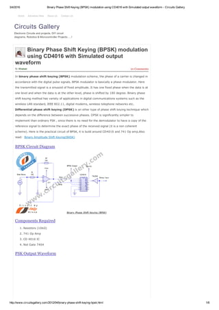
BPSK Circuit Diagram
Components Required
1. Resistors (10kΩ)
2. 741 Op Amp
3. CD 4016 IC
4. Not Gate 7404
PSK Output Waveform
Circuits Gallery
Electronic Circuits and projects, DIY circuit
diagrams, Robotics & Microcontroller Projects…..!
Home Advertise Here About Us Contact Us
6. 3/4/2016 Binary Phase Shift Keying (BPSK) modulation using CD4016 with Simulated output waveform Circuits Gallery
http://www.circuitsgallery.com/2012/04/binaryphaseshiftkeyingbpsk.html 6/6
555 Circuits Alarm Circuits
Amplifiers Arduino
Basic Electronics Circuits
C Programs Beginner Guide
Charger Circuits Circuit Simulation
DIY Hobby Circuits
Electronics Animations
Electronics Softwares
Engineering Projects ESP8266
GPS Projects GSM Projects
Indicator Circuits Inverter Circuits
Java Applets MATLAB
Microcontroller Projects
Microprocessor Mikro C
OpAmp Circuits
Oscillator Circuits
PIC Microcontroller PLC
Power Supplies Proteus
Radio Circuits Robotics
School Projects
Simple Electronic Projects
Timer / Counters Tutorials
Uncategorized Video Lab
CircuitsGallery
31 ﻣﻘﻁﻊ ﻓﻳﺩﻳﻭ
ﺍﺷﺗﺭﺍﻙ 999+
Gallery of Circuits
Popular Circuits
Simple low power Inverter Circuit
(12V DC to 230V or 110V AC)
diagram using CD4047 and IRFZ44
power MOSFET
Top 10 Simple 555 Timer Projects
Kits for Students
12v Battery Charger Circuit with
Auto Cut off
Top 10 Science fair Electronics
projects for School students
Home security alarm system circuit
diagram
Automatic water tank level controller
motor driver circuit Engineering
project without Microcontroller
Powered by iSt@r Group of Technologies