
Recommended
More Related Content
Similar to Geometric design of roads - Highways.docx
Similar to Geometric design of roads - Highways.docx (20)
More from sydneyaugust1
Recently uploaded
Recently uploaded (20)
Geometric design of roads - Highways.docx
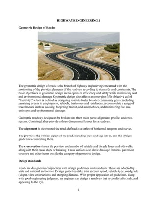
- 1. 1 HIGHWAYS ENGINEERING 1 Geometric Design of Roads: The geometric design of roads is the branch of highway engineering concerned with the positioning of the physical elements of the roadway according to standards and constraints. The basic objectives in geometric design are to optimize efficiency and safety while minimizing cost and environmental damage. Geometric design also affects an emerging fifth objective called "livability," which is defined as designing roads to foster broader community goals, including providing access to employment, schools, businesses and residences, accommodate a range of travel modes such as walking, bicycling, transit, and automobiles, and minimizing fuel use, emissions and environmental damage. Geometric roadway design can be broken into three main parts: alignment, profile, and cross- section. Combined, they provide a three-dimensional layout for a roadway. The alignment is the route of the road, defined as a series of horizontal tangents and curves. The profile is the vertical aspect of the road, including crest and sag curves, and the straight grade lines connecting them. The cross section shows the position and number of vehicle and bicycle lanes and sidewalks, along with their cross slope or banking. Cross sections also show drainage features, pavement structure and other items outside the category of geometric design. Design standards Roads are designed in conjunction with design guidelines and standards. These are adopted by state and national authorities. Design guidelines take into account speed, vehicle type, road grade (slope), view obstructions, and stopping distance. With proper application of guidelines, along with good engineering judgment, an engineer can design a roadway that is comfortable, safe, and appealing to the eye.
- 2. 2 Profile The profile of a road consists of road slopes, called grades, connected by parabolic vertical curves. Vertical curves are used to provide a gradual change from one road slope to another, so that vehicles may smoothly navigate grade changes as they travel. Sag vertical curves are those that have a tangent slope at the end of the curve that is higher than that of the beginning of the curve. When driving on a road, a sag curve would appear as a valley, with the vehicle first going downhill before reaching the bottom of the curve and continuing uphill or level. Crest vertical curves are those that have a tangent slope at the end of the curve that is lower than that of the beginning of the curve. When driving on a crest curve, the road appears as a hill, with the vehicle first going uphill before reaching the top of the curve and continuing downhill. The profile also affects road drainage. Very flat roads and sag curves may have poor drainage, and steep roads have high velocity flows. Common Terminologies in Geometric Design BVC = Beginning of Vertical Curve EVC = End of Vertical Curve = initial roadway grade, expressed in percent = final roadway grade, expressed in percent A = absolute value of the difference in grades (initial minus final), expressed in percent = Height of eye above roadway, measured in meters or feet = Height of object above roadway, measured in meters or feet L = curve length (along the x-axis) PVI = point of vertical interception (intersection of initial and final grades) Tangent elevation = elevation of a point along the initial tangent x = horizontal distance from BVC Y (offset) = vertical distance from the initial tangent to a point on the curve Y’ = curve elevation = tangent elevation - offset Sag Curves Sag vertical curves are curves which, when viewed from the side, are concave upwards. This includes vertical curves at valley bottoms, but it also includes locations where an uphill grade becomes steeper, or a downhill grade becomes less steep. The most important design criterion for these curves is headlight sight distance. When a driver is driving on a sag curve at night, the sight distance is limited by the higher grade in front of the vehicle. This distance must be long enough that the driver can see any obstruction on the road and stop the vehicle within the headlight sight distance. The headlight sight distance (S) is determined by the angle of the headlight and angle of the tangent slope at the end of the curve. By first finding the headlight sight distance (S) and then solving for the curve length (L) in each
- 3. 3 of the equations below, the correct curve length can be determined. If the S<L curve length is greater than the headlight sight distance, then this number can be used. If it is smaller, this value cannot be used. Similarly, if the S>L curve length is smaller than the headlight sight distance, then this number can be used. If it is larger, this value cannot be used. These equations assume that the headlights are 600 mm above the ground, and the headlight beam diverges 1 degree above the longitudinal axis of the vehicle. Crest Curves. Crest vertical curves are curves which, when viewed from the side, are convex upwards. This includes vertical curves at hill crests, but it also includes locations where an uphill grade becomes less steep, or a downhill grade becomes steeper. The most important design criterion for these curves is stopping sight distance. This is the distance a driver can see over the crest of the curve. If the driver cannot see an obstruction in the roadway, such as a stalled vehicle or an animal, the driver may not be able to stop the vehicle in time to avoid a crash. The desired stopping sight distance (S) is determined by the speed of traffic on a road. By first finding the stopping sight distance (S) and then solving for the curve length (L) in each of the equations below, the correct curve length can be determined. The proper equation depends on whether the vertical curve is shorter or longer than the available sight distance. Normally, both equations are solved, then the results are compared to the curve length. Sight Distance > Curve Length (S>L) Sight Distance < Curve Length (S<L) US standards specify the height of the driver’s eye is defined as 1080 mm above the pavement, and the height of the object the driver needs to see as 600 mm, which is equivalent to the taillight height of most passenger cars. For bicycle facilities, the cyclist's eye height is assumed to be at 1.4 m, and the object height is 0 mm, since a pavement defect can cause a cyclist to fall or lose control. Alignment Horizontal alignment in road design consists of straight sections of road, known as tangents, connected by circular horizontal curves. Circular curves are defined by radius (tightness) and deflection angle (extent). The design of a horizontal curve entails the determination of a minimum radius (based on speed limit), curve length, and objects obstructing the view of the driver. Using the American Association of State Highway and Transportation Officials (AASHTO) standards, an engineer works to design a road that is safe and comfortable. If a horizontal curve has a high speed and a small radius, an increased superelevation (bank) is needed in order to assure safety. If there is an object obstructing the view around a corner or curve, the engineer must work to ensure that drivers can see far enough to stop to avoid an accident or accelerate to join traffic.
- 4. 4 Critical Geometric Terminologies R = Radius PC = Point of Curvature (point at which the curve begins) PT = Point of Tangent (point at which the curve ends) PI = Point of Intersection (point at which the two tangents intersect) T = Tangent Length C = Long Chord Length (straight line between PC and PT) L = Curve Length M = Middle Ordinate, now known as HSO - Horizontal Sightline Offset (distance from sight-obstructing object to the middle of the outside lane) E = External Distance = Coefficient of Side Friction u = Vehicle Speed = Deflection Angle Cross section The cross section of a roadway can be considered a representation of what one would see if an excavator dug a trench across a roadway, showing the number of lanes, their widths and cross slopes, as well as the presence or absence of shoulders, curbs, sidewalks, drains, ditches, and other roadway features. Lane width The selection of lane width affects the cost and performance of a highway. Typical lane widths range from 3 metres to 3.6 metres. Wider lanes and shoulders are usually used on roads with higher speed and higher volume traffic, and significant numbers of trucks and other large vehicles. Narrower lanes may be used on roads with lower speed or lower volume traffic. Narrow lanes cost less to build and maintain, but also reduce the capacity of a road to convey traffic. On rural roads, narrow lanes are likely to experience higher rates of run-off-road and head-on collisions. Wider roads increase the time needed to walk across, and increase storm water runoff.
- 5. 5 Cross slope Cross slope describes the slope of a roadway perpendicular to the centerline. If a road were completely level, water would drain off it very slowly. This would create problems with hydroplaning, and ice accumulation in cold weather. In tangent (straight) sections, the road surface cross slope is commonly 1-2% to enable water to drain from the roadway. Cross slopes of this size, especially when applied in both directions of travel with a crown point along the centerline of a roadway are commonly referred to as "normal crown" and are generally unnoticeable to traveling motorists. In curved sections, the outside edge of the road is superelevated above the centerline. Since the road is sloped down toward the inside of the curve, gravity draws the vehicle toward the inside of the curve. This causes a greater proportion of centripetal force to supplant the tyre friction that would otherwise be needed to negotiate the curve. Superelevation slopes of 4 to 10% are applied in order to aid motorists in safely traversing these sections, while maintaining vehicle speed throughout the length of the curve. An upper bound of 12% was chosen to meet the demands of construction and maintenance practices, as well as to limit the difficulty of driving a steeply cross-sloped curve at low speeds. In areas that receive significant snow and ice, most agencies use a maximum cross slope of 6 to 8%. While steeper cross slope makes it difficult to traverse the slope at low speed when the surface is icy, and when accelerating from zero with warm tyres on the ice, lower cross slope increases the risk of loss-of- control at high speeds, especially when the surface is icy. Since the consequence of high speed skidding is much worse than that of sliding inward at a low speed, sharp curves have the benefit of greater net safety when designers select up to 8% superelevation, instead of 4%. A lower slope of 4% is commonly used on urban roadways where speeds are lower, and where a steeper slope would raise the outside road edge above adjacent terrain. The equation for the desired radius of a curve, shown below, takes into account the factors of speed and superelevation (e). This equation can be algebraically rearranged to obtain desired rate of superelevation, using input of the roadway's designated speed and curve radius. The American Association of State Highway and Transportation officials (AASHTO) provides a table from which desired superelevation rates can be interpolated, based on the designated speed and radius of a curved section of roadway. This table can also be found in road design guides and manuals. Recent research has shown that, considering rollover risk for heavy vehicles (semitrailers & buses), which have a relatively high centre-of-gravity, the above equation yields cross slope values which are too low. Safety Effects of Road Geometry The geometry of a road influences its safety performance. While studies of contributing factors to road accidents show that human factors predominate, roadway factors are the second most common category, with vehicle factors last.
- 6. 6 Design consistency. Collisions tend to be more frequent in locations where a sudden change in road character violates the driver's expectations. A common example is a sharp curve at the end of a long tangent section of road. The concept of design consistency addresses this by comparing adjacent road segments and identifying sites with changes the driver might find sudden or unexpected. Locations with large changes in the predicted operating speed are likely to benefit from additional design effort. A horizontal curve with a significantly smaller radius than those before it may need enhanced curve signs. This is an improvement on the concept of design speed, which only sets a lower limit for geometric design. In the example given above, a long tangent followed by a sharp curve would be acceptable if a 30 mph (... kph) design speed was chosen. Design consistency analysis would flag the decrease in operating speed at the curve. Safety Effects of Alignment. The safety of a horizontal curve is affected by the length of the curve, the curve radius, whether spiral transition curves are used, and the superelevation of the roadway. For a given curve deflection, crashes are more likely on curves with a smaller radius. Spiral transitions decrease crashes, and insufficient superelevation increases crashes. A safety performance function to model curve performance on two-lane roads is: bharat Where: AMF = Accident Modification Factor, a multiplier that describes how many more crashes are likely to occur on the curve compared to a straight road Lc = Length of the horizontal curve in miles. R = Radius of the curve in feet. S = 1 if spiral transition curves are present = 0 if spiral transition curves are absent Safety Effects of Cross Section Cross slope and lane width affect the safety performance of a road. Certain types of crashes, termed "lane departure crashes", are more likely on roads with narrow lanes. These include run-off-road collisions, sideswipes, and head-on collisions. For two-lane rural roads carrying over 2000 vehicles per day, the expected increase in crashes is: Lane width Expected increase in crashes 3.7m 0% 3.4m 5% 3.0m 30% 2.7m 50% The effect of lane width is reduced on urban and suburban roads[11] and low volume roads. Insufficient superelevation will also result in an increase in crash rate. The expected increase is shown below:
- 7. 7 Superelevation deficiency Expected increase in crashes for cars Expected increase in crashes for heavy trucks[12] <0.01 0% <5% 0.02 6% 10% 0.03 9% 15% 0.04 12% 20% 0.05 15% 25% Sight distance Road geometry affects the sight distance available to the driver. Sight distance, in the context of road design, is defined as "the length of roadway ahead visible to the driver."[1] Sight distance is how far a road user (usually a vehicle driver) can see before the line of sight is blocked by a hill crest, or an obstacle on the inside of a horizontal curve or intersection. Insufficient sight distance can adversely affect the safety or operations of a roadway or intersection. The sight distance needed for a given situation is the distance travelled during the two phases of a driving maneuver: perception-reaction time (PRT), and maneuver time (MT). Perception- reaction time is the time it takes for a road user to realize that a reaction is needed to a road condition, decided what maneuver is appropriate, and start the maneuver. Maneuver time is the time it takes to complete the maneuver. The distance driven during perception-reaction time and maneuver time is the sight distance needed. During highway design and traffic safety investigations, highway engineers compare the available sight distance to how much sight distance is needed for the situation. Depending on the situation, one of three types of sight distances will be used: Stopping sight distance Stopping sight distance is the distance traveled during perception-reaction time (while the vehicle driver perceives a situation requiring a stop, realizes that stopping is necessary, and applies the brake), and maneuver time (while the driver decelerates and comes to a stop). Actual stopping distances are also affected by road conditions, the mass of the car, the incline of the road, and numerous other factors. For design, a conservative distance is needed to allow a vehicle traveling at design speed to stop before reaching a stationary object in its path. Typically the design sight distance allows a below-average driver to stop in time to avoid a collision. Decision sight distance] Decision sight distance is used when drivers must make decisions more complex than stop or don't stop. It is longer than stopping sight distance to allow for the distance traveled while making a more complex decision. The decision sight distance is "distance required for a driver to detect an unexpected or otherwise difficult-to-perceive information source or hazard in a roadway environment that may be visually cluttered, recognize the hazard or its threat potential, select an appropriate speed and path, and initiate and complete the required maneuver safely and
- 8. 8 efficiently". Ideally, roads are designed for the decision sight distance, using 6 to 10 seconds for perception-reaction time and 4 to 5 seconds to perform the right maneuver. Intersection sight distance] Intersection sight distance is the sight distance needed to safely proceed through an intersection. The distance needed depends on the type of traffic control at the intersection (uncontrolled, yield sign, stop sign or signal), and the maneuver (left turn, right turn, or proceeding straight). All-way stop intersections need the least, and uncontrolled intersections require the most. Intersection sight distance is a key factor in whether no control or yield control can be safely used, ot more restrictive control in needed. Corner sight distance. Corner sight distance (CSD) is the road alignment specification which provides a substantially clear line of sight so that the driver of a vehicle, bicyclist or pedestrian waiting at the crossroad may safely anticipate the driver of an approaching vehicle. Corner sight provides an adequate time for the waiting user to either cross all lanes of through traffic, cross the near lanes and turn left, or turn right, without requiring through traffic to radically alter their speed. Uncontrolled and yield controlled intersections Uncontrolled and yield (give way) controlled intersections require large sight triangles clear of obstructions in order to operate safely. At uncontrolled intersections, the basic right-of-way rules apply (either yield to the vehicle on the right, or the boulevard rule, depending on the location). Vehicle drivers must be able to see traffic approaching on the intersecting road at a point where they can adjust their speed, or stop if need be, to yield to the other traffic before reaching the intersection. It isn't the only criterion for allowing these types of intersection control. Changing an intersection to stop control is a common response to poor safety performance. Two-way stop control When determining corner sight distance, a set back distance for the vehicle waiting at the crossroad must be assumed. Set back for the driver of the vehicle on the crossroad has been standardized by some state MUTCDs and design manuals to be up to a minimum of 3m plus the shoulder width of the major road but not less than 6m. However, the Federal MUTCD requires that a stop line, if used, shall be at least 1m from the nearest travel lane. Line of sight for corner sight distance is to be determined from a 1.1m eye height at the vehicle driver's location on the minor road to a 1.3m object height in the center of the approaching lane of the major road. Corner sight distance; is equivalent to a specified time gap at the design speed required for a stopped vehicle to turn right or left. For passenger vehicles at two lane intersections, this time gap equivalence is commonly a distance 7.5 seconds away at the design speed. Longer gaps are required for trucks and buses, and for multilane roads. Generally, the public right-of-way should include and maintain this line- of-sight.
- 9. 9 All-way stop control and signalized intersections] Drivers at intersections with all-way stop control or traffic signals need the least sight distance. At all-way stops, drivers need to be able to see vehicles stopped at other approaches. At signals, drivers approaching the intersections need to see the signal heads. In jurisdictions that allow right turn on red, drivers in the right lane stop control need the same sight distance as two-way stop control. Although not needed during normal operations, additional sight distance should be provided for signal malfunctions and power outages. Effects of insufficient sight distance Many roads were created long before the current sight distance standards were adopted, and the financial burden on many jurisdictions would be formidable to: acquire and maintain additional right-of-way; redesign roadbeds on all of them; or implement future projects on rough terrain, or environmentally sensitive areas. In such cases, the bare minimum corner sight distance should be equal to the stopping sight distance. While a corner sight distance which far exceed the braking distance at the design speed should be afforded to the driver, he or she is still generally required to maintain such control and operating speed as to be able to stop within the Assured Clear Distance Ahead (ACDA), and the basic speed rule always applies. Jurisdictions often provide some level of design immunity against government claims actions, in such cases. Warning signs are often used where sight distance is insufficient. The US MUTCD requires Stop Ahead, Yield Ahead or Signal Ahead signs at intersections where the traffic control device is not visible from a distance equal to the stopping sight distance at speed of approaching traffic. Hill Blocks View signs can be used where crest vertical curves restrict sight distance. However, many jurisdictions still expect drivers to use ordinary care regarding conditions readily apparent to a driver, without the prompting of a sign. The care and focus ordinarily required of a driver against certain types of hazards may be somewhat amplified on roads with lower functional classification. The probability of spontaneous traffic increases proportionally to the density of access points, and this density should be readily apparent to a driver even when a specific access point is not. For this reason, full corner sight distance is almost never required for individual driveways in urban high-density residential areas, and street parking is commonly permitted within the right-of-way. References Internate; wikipedia