1. * GB780195 (A)
Description: GB780195 (A) ? 1957-07-31
Improvements relating to hub pullers and like articles
Description of GB780195 (A)
I, ERIC FRANK ALLCHIN, a British Subject,
of 137 High Street, Aston, Birmingham 6, in the County of Warwick, do
hereby declare the invention, for which I pray that a patent may be
granted to me, and the method by which it is to be performed, to be
particularly described in and by the
following statement: -
This invention relates to hub pullers and like articles for removing
hubs or like members from an axle or other shaft of the kind
comprising a body portion, a thrust member adapted to enage the axle
or other member and being mounted on or connected to said body portion
and adapted to be displaced relatively thereto in a direction which,
in the operative position of the puller, is parallel or substantially
parallel to the axis of the axle or shaft from which the hub or like
member is to be removed, and two or more arms, each adapted to be
engaged at one end with the body portion of the puller and at the
other end to engage over and be secured to a projecting stud on the
hub or like member.
The object of the present invention is to provide an improved
construction.
According to the present invention I provide a hub puller or like
article of the above-mentioned kind wherein the studengaging end of
each arm is of ring-like form provided with an internal shoulder and
adapted to receive adaptor rings having apertures of different
diameters, said studengaging end being pivotally associated with the
remainder of the arm.
Conveniently the arm may be of bifurcated form at one end, the
stud-engaging end being pivotally mounted between the limbs thus
formed. Alternatively, the end of the arm remote from the body portion
may be pivotally connected to a forked member, with the stud-engaging
end being Pr,-ice 3s. 6d.1 pivotally mounted between the arms and the
2. fork.
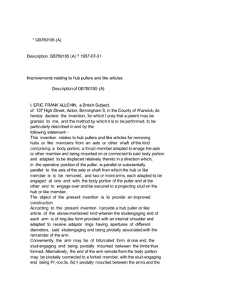
The invention is illustrated in the accompanying drawing
wherein:Figure 1 is a part sectional side elevation of one form of
puller; Figure 2 is a detail showing the one arm thereof, Figure 3 is
a view similar to Figure 1 but showing an alternative construction of
puller; and Figure 4 is a detail of one arm of the puller shown in
Figure 3.
In the form of my invention illustrated in Figures 1 and 2 wherein it
is applied to a hub puller for removing the wheel hubs of vehicles
from the axles on which they are mounted, the puller comprises a main
body portion 10 which is provided with a central tapped opening 11
through which a screw-threaded thrust block or shaft 12 is adapted to
pass. This body portion 10 of the puller is of disc-like form and that
face thereof which is remote from the hub when the puller is in its
operative position is provided with an annular groove 13 the purpose
of which will be explained hereafter.
One end of the threaded thrust shaft 12 is formed into hexagonal or
other noncircular form 14 whereby it may be engaged by a suitable tool
for turning the shaft 12 and the other end thereof is provided with an
axially disposed bore 15 in which a cylindrical bearing block 16 may
be disposed, this bearing block 16 forming the actual contacting face
with the end of the axle 17. With such an arrangement one or more
bearing blocks 16 of differing lengths can be provided, thus
increasing the adaptability of the puller.
Conveniently, five arms 18 may be provided for effecting a connection
between the body 10 of the puller and the hub 19 itself.
and each arm 18 may be formed from two 780,195 1PATENT SPECIFICATION
Date of fing Com'72plete Specification: May 31, 1955.
An p-lpicflic,1 Daite: May 29, 19.54. No. 15978154.
Complete Specification Published: July 31, 1957.
Index at Acceptance:-Class 61, Y6E.
International Classification:-B25b.
COMPLETE SPECIFICATION.
Improvements relating to Hub Pullers and like Articles.
s0 forgings which are secured together by a suitable nut and bolt 20.
The one end 21 of each forging is of hook shape and when the forgings
are secured together to form a single arm the hook shaped ends 21 of
each forging are disposed in abutting face to face relationship,
whilst the opposite ends thereof, as shown at 22, are spaced apart due
to each forging being cranked adjacent this other end. This other end
22 of each forging is provided with a transverse aperture 23 so that
it forms a bearing for a ring-like stud engaging member 24.
Each stud engaging member 24 is, as stated above, of ring-like form
and is provided at opposite sides with a Dair of flats from which
3. project outwardly lugs 25 adapted to engage the transverse apertures
23 formed in the arms 18. Thus, the stud engaging members 24 can be
rotated relative to the arms 18.
Each stud engaging member 24 is provided with an internal annular
shoulder 26 so that it is in effect provided with two internal
diameters and suitable adaptor rings 27 are provided which can be
dropped into place within the main ring 24, these adaptor rings 27
having differing internal diameters so that a close fit can be
obtained between the stud engaging ring 24 and studs 28 of differing
diameters.
In operation the puller is set up with the bearing block 16 engaging
against the axle 17 and with the arms 18 hooked over the body portion
10 so that the hooked ends 21 thereof engage within the annular groove
13 aforesaid and the stud engaging rings 24 on the opposite ends 21 of
the arms 18 are located over the studs 28 and the wheel nuts 29 are
then screwed on to the studs 28 so as to secure the arms 18 to the
hub. The threaded thrust block 12 is then rotated, thus drawing the
body disc 10 UD this threaded stud 12 away from the axle i7 and thus
drawing the hub 19 off the axle 17.
The construction shown in Figures 3 and 4 shows an alternative form of
puller for removing the wheel hubs of vehicles from the axles on which
they are mounted. In this construction the screw threaded shaft -12 is
provided with a tommy bar type handle 30 and the shaft 12 has mounted
therein a hydraulic assembly which is adapted to be operated by a
screw threaded member 31 which projects axially from the shaft 12.
With such an arrangement the thrust is exerted through the medium of
the hydraulic means as opposed to the screw thread which is only
employed in the construction shown in Figures 1 and 2.
The body 10 of the puller is again of ring-like form but is provided
with a number of circumferentially spaced apertures 32 which are each
adapted to receive studs 33 which are each provided with a lug 34
whereby the upper bifurcated end 35 of the puller arm 18 can be
pivotally supported.
The lower end of each arm 18 is pivotally secured by means of a bolt
36 to a forked member 37 the lower ends of which pivotally house the
cup member 24 in the same manner as described above with reference to
Figures 1 and 2.
In this construction the provision of the plurality of apertures 32 in
the body portion 10 enables the arms to be adjustably located in the
desired circumferential position.
The provision of stud engaging rings which are rotatable relative to
the arms S9I ensures that, regardless of the pitch circle diameter of
the studs on the hub, the rings are concentric with the studs so that
no lateral thrust is exerted on the studs.
4. * Sitemap
* Accessibility
* Legal notice
* Terms of use
* Last updated: 08.04.2015
* Worldwide Database
* 5.8.23.4; 93p