Andrea Hill Featured in Canadian Lawyer as SkyLaw Recognized as a Top Boutique
4561 4565.output
1. * GB784968 (A)
Description: GB784968 (A) ? 1957-10-23
Improvements relating to clutches
Description of GB784968 (A)
PATENT SPECIFICATION
Inventors: EMIL FUNKE and WERNER 7 PEDDINGHAUS Date of application and
filing Complete Specification: Nov 7, 1955.
No 31793/55.
Complete Specification Published: Oct 23, 1957.
Index at acceptance:-Class 80 ( 2), CIA( 3 A: 4: 7 A: 13 A), PIM( 1 B:
4 B), P 4.
International Classification:-FO 6 d.
COMPLETE SPECIFICATION
Improvements relating to Clutches We, PAUL CARL PEDDINGHAUS and WERNER
PEDDINGHAUS, both German Citizens, trading as the firm of PAUL FERD
PEDDINGH Aus, of Gevelsberg i/Westf Germany, do hereby declare the
invention, for which we pray that a patent may be granted to us, and
the method by which it is to be performed, to be particularly
described in and by the following statement: -
In industrial machines and especially machine tools, it is often
necessary that, on disconnection of the power drive, the machine
should stop with the main driving shaft in an accurately determined
position.
Such machines are, therefore, driven through controllable clutches,
which disengage at the termination of a complete revolution, or of a
number of complete revolutions.
The present invention relates to a clutch in which the driving member
comprises an annular felloe having slots or recesses disposed around
its inner periphery and the driven member has a radially movable
detent which is arranged to engage with any of the slots, or recesses
and is movable by a control member into a position to disengage the
clutch and stop the driven member in a predetermined position.
According to the invention, the slots or recesses and the portion of
the detent arranged to engage therein are tapered radially outwards
2. The connection between the two members of the clutch is, therefore,
without play, and will be properly maintained even after a certain
amount of wear has occurred.
The clutch engages almost immediately and couples positively on
actuation of its control and which, therefore, prevents initial racing
of the driving member.
The driving member may comprise a gear wheel having a sufficiently
large diameter to enable a large number of slots to be formed on the
inner periphery of the felloe On operating the clutch, therefore, the
gear wheel need rotate through only a small angle before one of the
slots is engaged by the detent and lPrice 3 s -6 d l 84968 the two
members of the clutch are positively coupled.
As the negative torques produced by an initial overrunning of the
driven portion of 50 the coupling are smaller than the positive
torques transmitted during drive, the clutch can advantageously be
formed in such a manner that the flanks of the slots leading in the
direction of rotation of the driving mem 55 ber are of less height
than the trailing flanks, there being provided in front of the slots
oblique or curved surfaces extending gradually towards the inner
circumference of the felloe This affords the advantage that the 60
detent is guided into and engages with the first slot reaching it when
the driving member is rotated even when the speed is high, and the
whole surface of the leading flank of the slot is effective
immediately at the be 65 ginning of the transmission of the driving
torque.
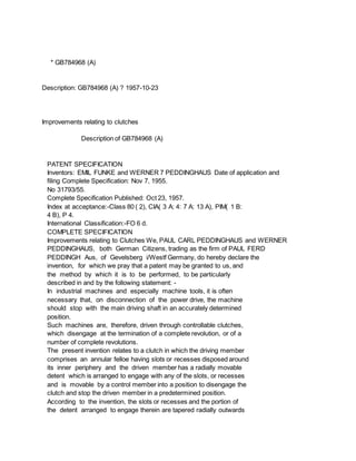
An example of a clutch according to the invention is shown in the
accompanying drawings in which: 70 Figure 1 shows an elevation of the
clutch; Figure 2 shows a cross-section taken on the line 1-1 of Figure
1; and Figure 3 shows a plan view of the clutch.
An arm 2 is attached by a hub to a shaft 75 1 A detent 3 radially
displaceable in a bore 4 of the arm 2, is pressed outwards by a
helical spring 7 and is formed with a laterally projecting stud 5 The
stud 5 projects through a slot 6 in the arm 2 A rail 8 80 pivoted on a
pin 9 controls the clutch The pin 9 is carried on a bracket 10 which
is attached to the body of the machine to be driven through the clutch
The rail 8 is connected to a lever 12 by which it may be 85 moved from
an operative position shown by broken lines in Figure 3 to an
inoperative position shown in the Figure by full lines.
The base of the rail 8 is formed with a controlling surface 11 and a
projection 22 90 The driving member in the form of a gear wheel 16 is
rotatably mounted on the hub of the arm 2 and is rotated by a drive
(not shown) in the direction of the arrow in Figure 1 A closure plate
23 fixed on the shaft 1 by a screw 24 holds the arm 2 axially in posiS
tion This plate also prevents axial displacement of the gear wheel 16
3. The felloe of the gear wheel is designated 20 In the circumference of
the felloe are slots 15 which are equidistant and the cross-section of
each of which viewed axially of the clutch diminishes towards its base
The leading flanks 18 of the slots 15 are shallower than the trailing
flanks 17 because there are provided in front of the slots inclined
curved surfaces which extend gradually to the inner circumference of
the felloe 20 The slot-engaging end of the detent 3 has a shape
corresponding to that of the slots and is designated 13 in Figure 1.
The clutch operates as follows: Initially the rail 8 is in the
position shown by full lines in Figures 2 and 3 In this position, the
end of the detent 3 is forced into engagement with one of the slots 15
in the fellce 20 of the gear wheel 16, by the action of the spring 7
On rotation, the gear wheel 16 carries with it the arm 2 and the shaft
1 If now the clutch is to be disengaged, the control rail 8 is brought
into the position shown by broken lines in Figures 2 and 3 by means of
the lever 12 As the arm 2 rotates, the stud 5 of the detent 3 contacts
the control surface 11 of the rail 8 and slides along it, so that the
detent 3 is pushed radially inwards against the action of the spring 7
The end 13 of the detent 3 is thereby withdrawn from the slot in the
felloe 20, and so the coupling between the gear wheel 16 and the arm 2
and the shaft 1 is released The rail 8 and the controlling surface 11
are so arranged that the end 13 of the detent 3 is disengaged when the
stud 5 is brought by the controlling surface 11 into the lower
position, designated 21 in Figure 1 In this position, the stud 5, as
shown at 21, is adjacent a projection 22 on the rail 8 The rotary
movement of the parts driven through the coupling is therefore, on
disconnection of the drive, stopped in a definitely fixed position
determined by the position of the projection 22.
In order to prevent rebound of the arrested masses, the rail 8 may be
provided with a latch having an oblique end formation, which is lifted
by the stud 5 (which in this case may be lengthened) and when the stud
5 engages the projection 22 on the rail 8, falls behind the stud For
this purpose the arrangement is preferably such, that the detent 3 is
moved back by the surface 11 on the rail 8 so far that the outer
extremity of the end 13 is in alignment with the outer surface 14 of
the arm 2.
When it is desired to re-engage the clutch, the rail 8 is again moved
by means of the lever 12 into the position shown in full lines.
This frees the stud 5 of the detent 3, so that the latter is forced
radially outwards by the action of the spring 7 and engages the first
slot 15 in the gear wheel 16 which it meets.
This engagement is facilitated by the inclined 70 or curved surfaces
provided in front of the slots in the direction of rotation, so that
engagement of the end 13 with a slot 15 is ensured even at high speeds
4. of rotation of the gear wheel 16, and the whole surface of con 75 tact
between the end 13 of the detent 3 and the flank 17 of the relevant
slot is immediately effective Owing to the wedge shape of the end 13
and the slots 15, the transmission is positive and free from play so
that also 80 negative torques can be resisted by the coupling and an
initial overrun of the driven parts is excluded.
The substantial advantages of the clutch according to the invention
are as follows 35 Due to the large number of slots 15 in the gear
wheel 16, an extremely quick, almost immediate engagement of the
clutch is possible As a result of the large diameter of the felloe 20
of the gear wheel 16, the detent 3 90 has to bear small forces only
and its section can be correspondingly small By positioning the clutch
in the gear wheel, the space normally required for a separately
constructed clutch is saved By means of the oblique 95 surfaces
provided before the slots, reliable engagement is ensured In an
operating position, the two clutch members are almost immediately and
positively connected with each other as a result of the wedge shaped
100 and play-free coupling surfaces.
* Sitemap
* Accessibility
* Legal notice
* Terms of use
* Last updated: 08.04.2015
* Worldwide Database
* 5.8.23.4; 93p
* GB784969 (A)
Description: GB784969 (A) ? 1957-10-23
Improvements in and relating to fountain brushes
Description of GB784969 (A)
PATENT SPECIFICATION
78 ' Date of Application and filing Complete Specification: Nov9, 1955
No
Application made in United States of America on Feb 18, 1955.
5. Complete Specification Published: Oct 23, 1957.
Index at acceptance:-Class 19, A 9, J.
International Classification:-A 46 b.
COMPLETE SPECIFICATION
Improvements in and relating to Fountain Brushes We, DUPLI-COLOR
PRODUCTS CO, INC, a Corporation organised and existing under the laws
of the State of Illinois, United States of America, of 2440 South
Michigan Avenue, Chicago, Illinois, United States of America, do
hereby declare the invention, for which we pray that a patent may be
granted to us, and the method by which it is to be performed, to be
particularly described in and by the following statement: -
This invention relates to fountain brushes for use in applying paint,
lacquers and other liquids to walls and the like and for covering
scratches and marks on metal, wood or unfinished surfaces of other
materials.
The aim of the invention is to provide a removable cap for such
brushes which locates the brush bristles in a sealed recess during
periods of non-use, and which is so shaped that damage to the bristles
cannot occur in applying or removing the cap.
According to the invention, the cap comprises a tubular member closed
at one end and formed with an elongated cylindrical skirt for aligning
the cap on the nozzle, and is provided with a small well of reduced
diameter near its closed end which snugly receives and shapes the
brush bristles, the mouth of the well being outwardly-flared so as to
guide the bristles smoothly into the well without bending them back
and so as to form a wedge seal with the tapered end of the nozzle.
Valved fountain brushes equipped with removable caps adapted to
retract the valve and brush into its container are known The
retraction of the brush into the container, however, frequently
displaces contents of the containers to pump slugs of liquid through
the nozzle into the cap When liquids such as quick-drying paints,
lacquers, enamels and stains, or like fluids having highly volatile
solvents, are stored in the container, this discharge may occur with
some force if the vap frth ale fluids in the containers creates a
super-atmospheric pressure As the valve is unseated by the cap, the
interior of the cap provides a lower pressure zone or receptacle for
the fluid These slugs can accumulate in the cap and a messy 50 nozzle
or clogged cap may result.
The present invention overcomes the disadvantage referred to above in
that the cap receives the brush in its extended position beyond the
nozzle in a brush-shaping recess 55 and is guided by the nozzle so
that the brush cannot be damaged If desired, the valve of the fountain
brush may be equipped with venting passages or the cap may partially
depress the brush to join the contents of the 60 nozzle with the cap
6. recess No discharge of slugs of liquid into the cap can result because
the brush depressing action is not sufficient to displace or pump
liquid from the nozzle and does not occur until the brush 65 is seated
in its small shaping recess which is just large enough to accommodate
the brush and does not have a slug receiving zone of lower pressure
than the fluid pressure in the nozzle 70 The caps provided in
accordance with the present invention are preferably equipped with
resiliently-deformable seal cups or liners which are impervious to the
vapours of solvents and the like ingredients in the contents 75 of the
fountain brush Suitable seal cups or liners can be formed of plastics
such as Polyethylene, Nylon and the like The cup or liner material
should not be softened or hardened by exposure to the contents of the
80 fountain brush and should always retain sufficient resiliency to
create a back pressure seal.
The seal cup equipped caps can be made to co-operate with the nozzle,
the valve, and 85 the side wall of the fountain brush to provide a
triple seal for the brush bristles In this arrangement, the bristles
are isolated from the atmosphere as well as from the contents of the
fountain brush If desired, 90 4,969 32100/55.
784,969 however, the bristles may remain in communication with the
contents of the fountain brush The cap is preferably threaded on the
nozzle to draw the seal up tightly against S the nozzle end The cap
end does not bottom on the nozzle so the cup can always be tightly
bottomed on the nozzle end.
Three examples of fountain brushes incorporating the invention are
shown in the accompanying drawings, in which:
Fig 1 is a side elevation of a fountain brush (including cap) in
accordance with the invention; Fig 2 is an enlarged longitudinal
crosssection with parts in elevation and with parts broken away, taken
on the line II-II in Fig.
1; Fig 3 is a view similar to Fig 2 but illustrating the manner in
which the cap is guided on the nozzle; Fig 4 is a view similar to Fig
2 but illustrating a modified cap which partially depresses the brush;
Fig 5 is a view similar to Fig 2 but illus-25 trating a modified valve
and seat arrangement; and Fig 6 is a view taken on the line VI-VI in
Fig 5.
The fountain brush 10 shown in Figs 1 to 3 comprises an elongated,
cylindrical barxrel 11 preferably composed of metal such as aluminium
or zinc, a nozzle 12 projecting from one end of the barrel and
preferably composed of a thermo-set plastic such as that -sold under
the Registered Trade Mark "Bakelite," a valve and brush unit 13
arranged to slide in the nozzle, a guide washer 14, preferably
composed of plastic, press fitted in the inner end of the nozzle -40
to hold the unit 13 in the nozzle, a spring 15 for urging the unit 13
7. downwards and a -heavy metal agitator ring 16 in the barrel 11 by
means of which the contents of the barrel can be agitated.
The nozzle 12 is closed by a relatively deep cap 17 preferably formed
of thermoset plastic material such as Bakelite This cap carries an
insert cup or liner 18 composed of resiliently deformable but
relatively rigid material such as that sold under the Registered Trade
Mark "Teflon," Nylon, or Polyethylene resins.
The nozzle 12 has a cylindrical configuration with an enlarged head 12
a press-fitted into the open end of the barrel 11 A reduced diameter
elongated cylindrical shank portion 12 b projects from the head 12 a
beyond the end of the barrel and has a rounded tapered dispensing end
12 c Threads 12 d B O are formed externally on the nozzle shank 12 b
adjacent the head 12 a A tapered valve seat 12 e is formed in the
dispensing end of the nozzle and converges to a circular orifice 12 f
in the centre of the nose 12 c.
The head 12 a has an enlarged counterbore 12 g in which the plastic
washer 14 is bottomed A cylindrical bore 12 i extends through the
nozzle shank 12 b to the tapered valve seat 12 e.
The brush unit 13 has a solid rod or shank 70 portion 13 a fitting
freely through the aperture in the washer 14 and adapted to project
into the aperture of the agitating ring 16 A head 13 b on the end of
this shank or rod 13 a provides a shoulder 13 c adapted to seat on 75
the tapered valve seat 12 e A reduced diameter hollow portion 13 d
projects from the shoulder 13 c freely through the orifice 12 f and
carries a tuft of brush bristles to form a brush B which projects
beyond the said ori 80 fice Lugs 13 e project radially at spaced
intervals around the circumference of the head to form guides for the
unit 13 by slidably engaging the bore 12 i whenever the unit is cocked
85 The spring 15 is bottomed on the lugs 13 e and head 13 b at one
end, and at the other end Is bottomed on the washer 14 The spring
surrounds the rod or shank portion 13 a and is effective to seat the
valve on the 90 nozzle seat and to urge the brush beyond the end of
the nozzle.
Fluid from the barrel 11 is in full communication with the nozzle
passage 12 i and is dispensed from this passage through the 95 orifice
12 f under the modulated control of the valve 13 c The bristles of the
brush B are stiff enough to allow pressure on the end of the brush to
unseat the valve and thus permit flow of liquid from the passage 12 i
100 to the brush bristles.
The ring 16 is submerged in liquid, such as paint, in the barrel 11
and is adapted to be surged through the liquid to agitate it and mix
the ingredients Since the ring 16 re 105 ceives the rod or shank 13 a
when it reaches the end of its stroke at the head 12 a, the fluid in
the barrel is subjected to a pump action which tends to force it into
8. the nozzle passage 12 i 110 The cap 17 comprises a tubular member
closed at one enid and formed with an elongated cylindrical side wall
or skirt 17 a defining a cylindrical bore 17 b of slightly larger
diameter than the portion 12 b of the nozzle 115 so that the skirt
freely embraces the nozzle.
The open end of the cap preferably has a thickened reinforced portion
17 c which has internal screw-threads 17 d for threaded engagement
with the screw-threads 12 d on the 120 nozzle The main side wall or
skirt 17 a of the cap beyond the thickened portion 17 c is preferably
fluted or grooved as shown at 17 e in Fig 1 to provide a hand grip for
loosening or tightening the cap on the foun 125 tain brush.
The closed end of the cap 17 f has a thickened side wall portion 17 o
to reinforce the closed end This thickened portion 17, defines a
reduced diameter bore 17 h in the 130 784,969 closed end of the cap
joined with the bore 17 b by a tapered shoulder 17 i.
The sealing liner 18 in the cap 17 has a cylindrical portion 18 a
sized to be pressfitted in the bore 17 h together with an end head 18
b Mor bottoming on -the closed end of the cap The liner 18 has an
enlarged head 18 c which is press-fitted in the bore 17 b and which
bottoms on the shoulder 17 i The liner defines recess 18 d having an
outwardlyfiared mouth or entrance 18 e The recess 18 d snugly receives
the brush B so as to shape the brush bristles and maintain them in
close associated relation to preserve a good painting end The mouth 18
e of the liner guides the brush bristles into the recess and also
forms a seat for providing a wedge seal with the nose 12 c of the
nozzle.
As illustrated in Fig 3, when the cap 17 is applied to the nozzle 12,
the skirt or wall 17 a of the cap slides over the nozzle portion 12 b
to align the liner 18 with the brush B before the brush engages the
liner The skirt 17 a is sufficiently long so that the cap is axially
aligned on the nozzle before the brush bristles can be engaged by the
liner.
Thus, the distance between the open end of the cap and the top of
thexecess 18 d exceeds the depth of the latter As the aligned cap is
advanced to the screw-threads 12 d of the nozzle, the brush smoothly
slides into the recess 18 d of the sealing cup while its bristles are
gathered together by the flared mouth 18 e of the recess When the cap
is threaded on to the nozzle, the brush bristles are 'surrounded by
the smooth confining side wall of the recess 18 d and cannot be
twisted or damaged However, if the bristles should stick to the side
wall of the recess 12 d as the cap is rotated, the entire brush unit
13 can rotate with the liner so that the bristles will not be twisted.
As illustrated in Fig 2, the liner head 18 c sealingly engages the
rounded nose 12 c of the nozzle when the cap is tightly threaded on
9. the nozzle In this arrangement, the brush B is thereby isolated or
sealed in the recess 18 d It is doubly sealed from communication with
the atmosphere by the sealing engagement of the liner head and nozzle
end and by the sealing engagement of the cap and nozzle threads In
addition, the brush is sealed from the contents of the nozzle by the
valve 13 c being seated on the valve seat 12 e Since the brush is not
retracted into the nozzle by the cap and since the recess 18 d is just
large enough to accommodate the brush and is sealed from the
atmosphere, the heretofore encountered discharge of slugs of liquid
accompanying the closing of fountain brushes having brushretracting
caps is avoided, and the recess will not be filled with the contents
of the container even if the valve is opened Any minute quantity of
fluid which flows through an opened -valve is taken up by the brush to
keep the liner relatively clean.
In the 'modification shown in Fig A, the fountain brush -is equipped
with a modified cap 1 i' ha Ving a modified seal liner 19 com 70 posed
of the Qsame material as the liner 18 shown in Figs 1-3 A thick end
wall 19 b is provided on the liner 19, and the recess 19 d is
shallower than the recess 18 d of the liner 18 75 When the cap 17 ' is
applied to the nozzle 12, it is -guided in the same manner as
illustrated in Fig 3 but before the cap 171 is tightened on the
nozzle, the end wall 19 b of the liner 19 abuts the end of the brush
13 to 80 retract the brush and open the valve 13-b.
The valve is only slightly opened and the brush is slightly retracted
when the cap is tightened on the nozzle In this arrangement,
therefore, the contents of the container 85 are joined with the recess
in the liner when the cap is seated on the nozzle so that the -brush
is not isolated from the reservoir as in the fountain brush shown in
Figs 1 to 3 This communication may sometimes be desirable 90 to keep
the brush exposed to the solvents in the barrel 11 However, the
partial retraction of the brush does not permit the heretofore
encountered pumping action effected by complete retraction of the
brush with the 95 cap.
In the second modification shown in Figs.
and 6, the fountain brush 101 is closed with a cap 17 which is
identical to that shown in Figs 1 to 3 Although the cap 17 does not
100 retract the brush, the brush remains in communication with the
contents of the nozzle when the cap seals the brush For this purpose,
the tapered valve seat 12 e of the nozzle is provided with one or more
grooves 20 and 105 the valve head 13 b is equipped with one or more
notches 21 at spaced intervals around the periphery thereof at the
valve shoulder 13 c Thus, even when the valve is closed, the passages
provided by the grooves or 110 notches 20 and 21 connect the contents
of the nozzle with the brush and the sealed brush in the liner 18
10. remain in communication with the fluids in the nozzle While the
grooves 20 in the valve seat and notches 21 115 in the valve have been
illustrated, it will be appreciated that either the grooves or the
notches could be used alone.
From the above description it will, therefore, be seen that the
invention provides a 120 fountain brush having an improved cap or seal
which isolates and shapes the brush and which is guided by the nozzle
of the fountain brush so that the brush bristles cannot be damaged in
applying the cap 125
* Sitemap
* Accessibility
* Legal notice
* Terms of use
* Last updated: 08.04.2015
* Worldwide Database
* 5.8.23.4; 93p
* GB784970 (A)
Description: GB784970 (A) ? 1957-10-23
Improvements in or relating to process for the production of a normally
solid, polymeric hydrocarbon material
Description of GB784970 (A)
A high quality text as facsimile in your desired language may be available
amongst the following family members:
BE542308 (A) FR1139655 (A)
BE542308 (A) FR1139655 (A) less
Translate this text into Tooltip
[81][(1)__Select language]
Translate this text into
The EPO does not accept any responsibility for the accuracy of data
and information originating from other authorities than the EPO; in
particular, the EPO does not guarantee that they are complete,
11. up-to-date or fit for specific purposes.
PATENT SPECIFICATION
Inventors: EDMUND FIELD and MORRIS FELLER
7849970 -C Date of Application and filing Complete Specification: Dec
2, 1955.
No 34578/55.
Complete Specification Published: Oct 23, 1957.
Index at acceptance:-Classes 1 ( 1), A 31 81; and 2 ( 6), P 2 (A: DIA:
FX: K 7), P 2 Pl(B: C: E 3), P 2 P( 3: 5: 6 A: 6 B: 6 X), P 2 T 2 (D:
E), P 7 A, P 7 D(IA: 13:1 X: 2 A 1), P 7 FX, P 7 K( 2: 7: 10), P 7 P 1
(B: C: E 3), P 7 P( 3: 5: 6 A 613: 6 X), P 7 T 2 (D: E).
International Classification:-B Olj CO 8 f.
COMPLETE SPECIFICATION
Improvements in or relating to process for the production of a
Normally Solid, Polymeric Hydrocarbon Material We, STANDARID OIL
COMPANY, a corporation organised under the laws of the State of
Indiana, United States of America, of 910, South Michigan Avenue,
Chicago, Illinois, United States of America, do hereby declare the
invention, for which we pray that a patent may be granted to us, and
the method by which it is to be performed, to be particularly
described in and by the following statement:This invention relates to
novel polymerization catalysts and to novel processes for their
employment In a more specific aspect, this invention relates to novel
catalysts and processes for the conversion of normally gaseous
n-alkenes or mixtures thereof with each other or with other
unsaturated materials, to produce normally solid products in the
presence of certain reactive hydrogen compound and oxides of
transition metals of Group 5 of the Periodic System (corresponding to
oxides of metals selected from Group 5 a of the Mendeleef Periodic
Table) The reactive hydrogen compounds are the hydrides of the alkali
metals and/or the non-radioactive alkaline earth metals.
One object of this invention is to provide novel and highly useful
catalysts and catalyst promoters for the preparation of normally
solid, high molecular weight polymers from gaseous feed stocks
containing n-alkenes.
Another object is to provide processes for the polymerization of
normally gaseous n-alkenes at higher rates and in higher yields than
those heretofore obtainable solely through the use of partially
reduced metal oxides, specifically, partially reduced oxides of metals
of Group 5 a of the Mendeleef Periodic Table An additional object is
to provide novel low temperature, low pressure processes for the
conversion of ethylene, propylene, 1-butene or their mixtures into
high molecular weight, lPrice 3 s 6 d l waxy, resinous or rubbery
12. materials An additional object is to provide polymers of high density,
greater stiffness and low water vapor permeability These and other
objects of the invention will become apparent from the ensuing
description thereof and a consideration of the annexed drawing.
The present invention provides a process for the production of a
normally solid hydrocarbon material, which comprises contacting a
normally gaseous n-alkene under polymerization conditions with a
reactive hydrogen compound from the class of alkali metal hydrides and
non-radioactive alkaline earth metal hydrides, and with a solid
catalyst comprising essentially an oxide or a salt of an oxyacid of a
metal selected from Group Sa of the Mendeleef Periodic Table and
separating the normally solid hydrocarbon material thus produced.
Briefly, the inventive process comprises the conversion of a feed
stock comprising essentially a normally gaseous n-alkene to high
molecular weight, normally solid materials by contact with catalytic
proportions of one or more of the oxides or salts of the oxyacids of
metals selected from Group 5 a of the Mendeleef Periodic Table and one
or more of the hydrides of the alkali metals and/or nonradioactive
alkaline earth metals It is usually desirable to extend the Group 5 a
metal oxide upon a support such as a difficultly reducible metal oxide
and also to activate said oxide by partial reduction before use, for
example, with various reducing gases such as hydrogen,
dehydrogenatable hydrocarbons or carbon monoxide The selected
polymerization temperature will depend upon the specific catalyst
systems selected for use, namely, upon the metal oxide and reactive
hydrogen compound.
In general the selected polymerization temperature is usually between
75 C, and 325 "C, usually 110 C to 275 "C, and preferably 220-260 'C
The polymerization can be effected even at atmospheric pressure,
although usually the rate is low The polymerization pressure may
extend to 15,000 or 20,000 p s i.
(pounds per square inch) or even higher pressures but will usually be
selected between and 5000 p s i g (pounds per square inch gauge), or,
most often, at about 1000 p s i g.
The normally solid materials produced by the catalystic conversion
tend to accumulate upon and within the solid catalyst, so it is
desirable to supply to the reaction zone a liquid medium which serves
both as a reaction medium and a solvent for the solid reaction
products Suitable liquid reaction media for polymerization include
various hydrocarbons, particularly an aromatic hydrocarbon such as
benzene, toluene or xylenes For the polymerization of propylene or
1-butene, less readily alkylatable reaction media such as
cycloparaffins, e g, cyclohexane or decahydronaphthalene, or
paraffins, e g, iso-octane, are preferred.
13. However, the conversion of the gaseous feed stock can be effected in
the absence of a liquid reaction medium or solvent and the catalyst
containing accumulated solid polymeric conversion products can be
treated from time to time, within or outside the conversion zone, to
effect removal of conversion products therefrom and, if necessary,
reactivation or regeneration of the catalyst for further use.
The inventive process is characterized by extreme flexibility both as
regards operating conditions and as regards the products producible
thereby Thus the present process can be effected over extremely broad
ranges of temperature and pressure The practice of the present process
can lead to grease-like homopolymers having an approximate molecular
weight range of 300 to 700, wax-like homopolymers having an
approximate specific viscosity ( x 105) between about 1000 and 10,000
and tough, resinous homopolymers having an approximate specific
viscosity ( x 106) of 10,000 to more than 300,000 l(?i relative 1) x
10 'l By the term "tough, resinous polyethylene " as used herein, we
mean polymer having a brittle point below 50 'C.
(A.S T M Method D 746-51 T), impact strength greater than two foot
pounds per inch of notch (A S T M Method D 256-47 T -Izod machine) and
minimum elongation at room temperature ( 25 C) of 100 %.
The process of the present invention can be employed to effect the
copolymerization of normally gaseous n-alkenes with each other and/or
with other polymerizable materials, such as iso-butylene,
t-butylethylene, tetrafluoroethylene, styrene and butadiene In
copolymerizations, the principal monomer is present in concentrations
between about 75 % 1 O and about 95 % 1 O by weight, based on the
weight of the total feed stock.
The reactive metal hydrides employed in the inventive process have the
general formula MH 1, wherein M represents an alkali metal or
non-radioactive alkaline earth metal and N represents its valence The
alkali metals are lithium, sodium, potassium, rubidium or caesium The
alkaline earth metals are beryl 70 lium, magnesium, calcium, strontium
and barium.
The hydrides of calcium, strontium and barium are readily prepared by
the interaction of hydrogen with the pure metals Thus 75 metallic
calcium reacts readily with hydrogen at 200 'C to produce Ca 1-
Calcium hydride can also be prepared by the reaction of Ca O with
magnesium and hydrogen, which produced calcium hydride containing Mgo
80 Strontium hydride can be prepared by the reaction of a stronitum
halide with lithium aluminum hydride (A E Finholt et al, J Am.
Chem Soc 69, 1199-1203 ( 1947) Beryllium and magnesium hydrides can be
prepared by 85 special methods known in the art The alkali metal
hydrides can be prepared by the interaction of hydrogen with the pure
metals and by other methods It will be understood that the specific
14. preparative methods involved form 90 no part of our invention and that
any method which yields the desired metal hydride can be employed
Usually the hydrides employed according to the present invention are
prepared outside the reator, but they may be 95 prepared in situ and
polymerization can then be effected in the reactor.
The employment of one or more of the aforesaid hydrides in the
reaction zone has numerous practical advantages, as compared 100 to
processes wherein the metal oxide catalysts are employed without said
hydrides Thus, when both the said hydrides and said metal oxide
catalysts are employed, high yields of solid polymers can be obtained
from ethylene, 105 the metal oxide-containing catalyst functions well
in the presence of large proportions of liquid reaction medium, the
metal oxide-containing catalyst retains strong polymerization activity
for a long period of time (long cata 110 lyst life), and polymers
having desirable ranges of physical and chemical properties can be
readily produced by controlling the reaction variables, etc, as will
appear from the detailed description and operating examples which 115
follow.
The function or functions of the metal -hydrides in the process of the
invention are not well understood The metal hydrides alone are not
catalysts for the polymerization of 120 ethylene or propylene to yield
high molecular weight, normally solid polymers under the conditions
described herein Yet, the metal hydrides co-function somehow with the
metal oxide catalyst to increase the productivity 125 (polymer yield)
of said catalyst, sometimes prodigiously It might be assumed that the
metal hydrides function merely to react with catalyst poisons which
might be present in small proportions of the order of a few parts 130
784,970 are such that support is in major amount, e g.
in the range of 1: 20 to 1: 1, or approximately 1: 10 We may employ
conditioned aluminametal oxide catalysts composed of gammaalumina base
containing about 1 to 80 %, pre 70 ferably 5 to 35 %, or approximately
10 %, of catalytic metal oxide supported thereon.
Although no reducing treatment need be effected on the metal oxide
catalysts when they are employed in the presence of reactive metal 75
hydrogen compounds, a reducing or conditioning treatment is preferred
in commercial processing The conditioning or reducing treatment of the
pentavalent Group 5 a metal oxide catalyst is preferably effected with
hydrogen 80 although other reducing agents such as carbon monoxide,
mixtures of hydrogen and carbon monoxide (water gas, synthesis gas,
etc), sulfur dioxide, hydrogen sulfide or dehydrogenatable
hydrocarbons may be employed Hydrogen can 35 be employed as a reducing
agent at temperatures between about 350 'C and about 850 'C, although
it is more often employed at temperatures within the range of 4500 C
to 6500 C.
15. The hydrogen partial pressure in the reduction 90 or conditioning
operation may be varied from sub-atmospheric pressures, for example
even 0.1 pound (absolute), to relatively high pressures up to 3000 p s
i g, or even more The simplest reducing operation may be effected 95
with hydrogen simply at about atmospheric pressure The partial
reduction of the metal oxide catalyst in which the metal is present in
its maximum valence state can be effected in the presence of the
reactive metal hydrogen 100 compound, prior to contacting the
combination of catalysts with the gaseous feed stock.
Lithium aluminum hydride, an exceptionally active reducing agent,
conditions and activates catalysts containing pentavalent Group 5 a
105 metal oxides even at temperatures as low as C, although in general
temperatures between 100 and 300 'C are employed In practice, for
example, a catalyst containing free or chemically combined V 0, or 110
(Co V 203) is treated with a suspension of Li Al H, in a hydrocarbon
solvent at weight ratios of about 0 01 to about 1 Li A 1 H per weight
of solid catalyst Sodium hydride (or sodium plus H) is effective in
partially reduc 115 ing and conditioning Group 5 a metal oxide
catalysts such as V 0, at temperatures above about 180 C and can be
employed in the same proportions as Li Al H 1 Reactive metal
borohydrides may likewise be employed to 120 effect partial
prereduction of the Group 5 a metal oxide catalysts, employing
essentially the same conditions as when Li Al H, is used.
The conditioning treatment hereinabove described is useful not only
for fresh catalyst, 125 but may also be desirable for catalyst which
has become relatively inactive in the polymerization step As will be
hereinafter described, the polymer formed in the polymerization
reaction must be continuously or inter 130 per million in ethylene,
propylene and/or in the liquid reaction medium; we have found,
however, that even extremely pure ethylene or propylene and liquid
reaction medium which have been contacted with alkali metal or with
calcium hydride under reaction conditions and directly thereafter
contacted in a separate zone with molybdenum oxide catalysts, do not
produce solid polymer in the high yields or quality which can be
attained by the process of the present invention.
It was further discovered that the claimed metal hydrides so activate
molybdena catalysts that solid polymers were obtained by contacting
ethylene with Mo O, alone, i e, without a support which functions
greatly to increase the surface area upon which Mo O, is extended.
The Group 5 a metal oxides which are employed in preparing catalysts
for this invention are the oxides of vanadium, niobium and tantalum
The selected catalytic metal oxide or mixture thereof can be extended
upon a variety of difficultly reducible metal oxides, for example upon
alumina, titania or zirconia; upon silica supports such as silica gel,
16. kieselguhr or diatomite; upon synthetic silicaalumina preparations,
upon naturally-occurring alumino-silicates, especially the
montmorillonites, such as occur in various clays or bleaching earths;
and even adsorptive carbon, which is however not preferred.
Vanadia or other vanadium-oxygen compound, such as cobalt vanadate,
may be incorporated in the catalyst base in any known manner, e g by
impregnation, coprecipitation, co-gelling, and/or absorption, and the
catalyst base and/or finished catalyst may be heatstabilized in the
known manners heretofore employed in the preparation of hydroforming
or hydrofining catalysts Cobalt, chromium, magnesium, calcium, zinc,
nickel and copper salts of vanadic, niobic and tantalic acids may also
be employed, with or without a support.
The catalyst may be stabilized with silica or with aluminum
ortho-phosphate or other known stabilizers or modifiers The catalyst
may contain calcium oxide or the base may be in the form of a zinc
aluminate spinel and it may contain appreciable amounts of zirconia or
titania Oxides of other metals such as magnesium, nickel, zinc,
vanadium, thorium and iron may be present in minor amounts, below 10
weight percent of the total catalyst.
Gamma-alumina, titania and zirconia supports for our catalysts may be
prepared in any known manner and the oxides of vanadium or other group
5 a metal may likewise be incorporated in, or deposited on, the base
in any known manner.
The relative proportions of support to the catalytic metal oxide are
not critical and may be varied throughout a relatively wide range such
that each component is present in amounts of at least approximately 1
weight percent The usual metal oxide-support ratios 784,970 mittently
removed from the catalyst particles, preferably by means of solvents,
and it is usually necessary or desirable to condition a catalyst
surface which has been thus freed to some extent from polymer, before
it is again employed for effecting polymerization When catalyst can no
longer be rendered sufficiently active by simple removal of polymer
and conditioning with a reducing gas as hereinabove described, it may
be regenerated by extraction with water or dilute aqueous acids,
thereafter burning combustible deposits therefrom with oxygen followed
by the conditioning step.
Detoxification of the catalysts by treatment with dilute aqueous
solutions of per-acids such as permolybdic, pervanadic or pertungstic
acids may be practiced, followed by hydrogen-conditioning of the
catalysts.
The proportion of alkali metal hydride may be varied between about 0
001 and about 2 parts by weight per part by weight of the metal oxide
catalysts (total weight of solid catalyst), more often between 0 01
and 0 25.
17. The proportion of alkaline earth metal hydride to metal oxide
catalysts (by weight) may be varied from about 0 01 to about 10,
usually between 0 1 and 2 The optimum proportions can readily be
determined in specific instances, by simple small-scale tests with the
specific feed stocks, liquid reaction medium, reaction medium:
catalyst ratio, catalyst, specific reactive metal hydrogen compound,
temperature, pressure and nature of the product which is desired.
The catalysts can be employed in various forms and sizes, e g, as
powder, granules, microspheres, broken filter cake, lumps, or shaped
pellets A convenient form in which the catalysts may be employed is as
granules of about 20-100 mesh/inch size range Pellets or granules
containing both the metal oxide catalyst and metal hydride may be
prepared and used in our process Very finely-divided catalysts can be
prepared by conventional methods such as grinding, or ball-milling.
The alkene or co-monomer may contain hydrogen and extraneous
hydrocarbons, as in refinery gas streams, for example, methane,
ethane, propane, and butanes However, it is usually preferred to
employ relatively concentrated alkene charging stocks When the
charging stocks contain a plurality of normally gaseous n-alkenes, all
may contribute to the production of resinous high molecular weight
products.
It is desirable to minimize or avoid the introduction of oxygen,
carbon dioxide, water or sulfur compounds into contact with the
catalysts.
Polymerization can be effected in the presence of Group 5 a oxide
catalysts and the reactive metal hydrides at temperatures between 750
C and 3250 C, usually at 1100 C.
to 2750 C or in a preferred narrower range of 220 to 260 'C The
conjoint use of polymerization temperatures between 220 and 260 C and
a liquid hydrocarbon reaction medium such as benzene, xylenes,
decahydronaphthalene or methyl decahydronaphthalenes, is highly
desirable in producing ethylene poly 70 mers having specific
viscosities ( x 103) ranging on the average from about 10,000 to about
30,000 when using continuous operations with relatively long on-stream
periods and clean catalysts 75 It has been found that the present
process can be employed for the production of relatively high
molecular weight hetero and homopolymers of normally gaseous n-alkenes
at relatively low pressures The process of the 80 present invention
can be effected to some extent even at atmospheric pressure The upper
limit of polymerization pressure is dictated by economic
considerations and equipment limitations and may be 10,000 p s i g,
20,000 85 p.s i g, or even more A generally useful and economically
desirable polymerization pressure range is between 200 and 5000 p s i
g, preferably between 500 and 1500 p s i g, e g about 1000 p s i g 90
18. The contact time or space velocity employed in the polymerization
process will be selected with reference to the other process
variables, catalysts, the specific type of product desired and the
extent of alkene conversion desired in 95 any given run or pass over
the catalyst In general, this variable is readily adjustable to obtain
the desired results In operations in which the alkene feed stock is
caused to flow continuously into and out of contact with the 100 solid
catalyst, suitable liquid hourly space velocities are usually selected
between 0 1 and volumes, preferably 0 5 to 5 or about 2 volumes of
alkene solution in a liquid reaction medium, which is usually an
aromatic hydro 105 carbon such as benzene, xylenes, or
tetrahydronaphthalene, or an alkane or a cyclo-aliphatic hydrocarbon,
such as decahydronaphthalene.
The amount of alkene in such solution may be in the range of 2 to 50 %
by weight, prefer 110 ably 2 to 10 weight percent or, for example, to
10 weight percent It was observed that when ethylene concentration in
the liquid reaction medium was reduced below about 2 weight per cent,
the molecular weight and 115 melt viscosity of the polymeric products
drops sharply The rate of ethylene polymerization tends to increase
with increasing concentration of the ethylene in the liquid reaction
medium.
However, the rate of ethylene (or other alkene) 120 polymerization to
form high molecular weight, normally solid polymers is preferably not
such as to yield said solid polymers in quantities which substantially
exceed the solubility thereof in said liquid reaction medium under 125
the reaction conditions, usually up to about 5-7 weight percent,
exclusive of the amounts of polymeric products which are selectively
adsorbed by the catalyst Although ethylene, or other alkene,
concentrations above 10 130 784,970 784,970 5 weight percent in the
liquid reaction medium may be used, solutions of polymer above 5% in
the reaction medium become very viscous and difficult to handle and
severe cracking or spalling of the solid metal oxide catalyst
particles or fragments may occur, resulting in catalyst carry-over as
fines with the solution of polymerization products and extensive loss
of catalyst from the reactor.
In batch operations, operating periods of between one-half and about
10 hours, usually between 1 and 4 hours, are employed and the reaction
autoclave is recharged with alkene feed stock as the pressure falls as
a result of the olefin conversion reaction.
The solvent: catalyst weight ratio can be varied in the range of about
5 to about 3000, or even higher for flow systems The employment of
high solvent: catalyst ratios, which is rendered possible by the
presence of one or more of the hydrides of an alkali metal or alkaline
earth metal in the reaction zone, is very important in obtaining high
19. yields of polymer.
Normally gaseous n-alkenes can also be polymerized in the gas phase
and in the absence of a liquid-reaction medium Upon completion of the
desired polymerization reaction it is then possible to treat the solid
catalyst for the recovery of the solid polymerization products, for
example by extraction with suitable solvents However, in the interests
of obtaining increased rates of alkene conversion and of continuously
removing solid conversion products from the catalyst, it is much
preferred to effect the conversion of the alkene in the presence of
suitable liquid reaction media The liquid reaction medium may also be
employed as a means of contacting the alkene with catalyst by
preparing a solution of the alkene feed stock in the liquid reaction
medium and contacting the resultant solution with the polymerization
catalyst.
The liquid reaction medium functions as a solvent to remove some of
the normally solid product from the catalyst surface.
Various classes of hydrocarbons or their mixtures which are liquid and
substantially inert under the polymerization conditions of the present
process can be employed Members of the aromatic hydrocarbon series,
particularly the mononuclear aromatic hydrocarbons, viz, benzene,
toluene, xylenes, mesitylene and xylene p-cymene mixtures can be
employed.
Tetrahydronaphthalene can also be employed In addition, one may employ
such aromatic hydrocarbons as ethylbenzene, isopropylbenzene, sec
butylbenzene, t butylbenzene, ethykltoluene, ethylxylenes,
hemimellitene, psuedocumene, prehnitene, isodurene,
diethylbenzenes,and isoamylbenzene.
Suitable aromatic hyrocarbon fractions can be obtained by the
selective extraction of aromatic naphthas, from hydro-forming
operations as distillates or bottoms, and from cycle stock fractions
of cracking operations.
One may also employ certain alkyl naphthalenes which are liquid under
the polymerization reaction conditions, for example,
1methyl-naphthalene, 2 isopropylnaphthalene, 70 and
1-n-amylnaphthalene, or commercially produced fractions containing
these hydrocarbons.
Certain classes of aliphatic hydrocarbons can also be employed as a
liquid hydrocarbon re 75 action medium in the present process Thus,
one may employ various saturated hydrocarbons (alkanes and
cycloalkanes) which are liquid under the polymerization reaction
conditions and which do not crack substantially 80 under the reaction
condition Either pure alkanes or cycloalkanes or commercially
available mixtures, freed of catalyst poisons, may be employed For
example, one may employ straight run naphthas or kerosenes containing
20. 85 alkanes and cycloalkanes Specifically, we may employ liquid or
liquefied alkanes such as npentane, n-hexane, 2,3-dimethylbutane,
noctane, iso-octane ( 2,2,4-trimethylpentane), ndecane, n-dodecane,
cyclohexane, methylcyclo 90 hexane, dimethylcyclopentane,
ethylcyclohexane, decahydronaphthalene, methyl decahydronaphthalenes
and dimethyl decahydronaphthalenes.
One may also employ a liquid hydrocarbon 95 reaction medium comprising
liquid olefins, e.g, n-hexenes, cyclohexene, octenes, and hexadecenes.
The normally solid polymerization products which are retained on the
catalyst surface or 100 grease-like ethylene polymers may themselves
function to some extent as a liquefied hydrocarbon reaction medium,
but it is highly desirable to add a viscosity-reducing hydrocarbon
such as those mentioned above, thereto 105 in the reaction zone.
The liquid hydrocarbon reaction medium should be freed of poisons
before use in the present invention by acid treatment, e g, with
anhydrous p-toluenesulfonic acid, sulfuric acid, 110 or by equivalent
treatments, for example with aluminum halides, or other Friedel-Crafts
catalysts, maleic anhydride, calcium, calcium hydride, sodium or other
alkali metals, alkali metal hydrides, lithium aluminum hydride, 115
hydrogen and hydrogenation catalysts (hydrofining), filtration through
a column of copper grains or 8th group metal, or by combinations of
such treatments.
C.P xylenes have been purified by refluxing 120 with a mixture of 8 w%
Mo O, on A 1,0, catalyst and Li AIH 4 1 ( 50 c c xylene-1 g Mo O,ALO
0-0 2 g Li Al H 4) at atmospheric pressure, followed by distillation
of the xylenes Still more effective purification of solvent can be 125
achieved by heating it to about 225 -250 C.
with either sodium and hydrogen or Na H in a pressure vessel.
Temperature control during the course of the alkene conversion process
can be readily accom 130 784,970 plished owing to the presence in the
reaction zone of a large liquid mass having relatively high heat
capacity The liquid hydrocarbon reaction medium can be cooled by heat
exchange inside or outside the reaction zone.
When solvents such as xylenes are employed some slight alkylation
thereof by ethylene can occur under the reaction conditions Propylene
is a far more reactive alkylating agent than ethylene and when
propylene or 1-butene is present in the feed, it is desirable to
employ a relatively non-alkylatable solvent such as
decahydronaphthalene The alkylate is removed with grease in the
present process, can be separated therefrom by fractional distillation
and can, if desired, be returned to the polymerization zone.
An illustrative flow diagram indicating one method by which the
process of our invention may be effected is set forth in the
accompanying drawing The alkene feed stock, e g, ethylene or an
21. ethylene-propylene mixture, is passed through compressor 10 wherein
the pressure thereof is raised to a suitable value, for example,
between 500 and 2000 pounds, thence into chamber 11, which is provided
with a suitable deoxygenating agent such as metallic copper at 1500 C,
then into chamber 12 which is provided with a dehydrating agent such
as adsorptive alumina, anhydrous calcium sulfate, silica gel or
equivalent drying reagent.
The dried feed stock is passed from chamber 12 into chamber 13 wherein
carbon dioxide is removed from the charging stock Chamber13 is
provided with a suitable reagent, for example, sodium hydroxide
deposited upon asbestos or with any other efficacious decarbonating
reagent The feed stock thus purified usually contains less than 50
parts per million of oxygen and has a dew point below 450 C.
The purified feed stock is then passed into an absorber 14, wherein it
meets a counterflow of solvent Solvent or liquid reaction medium may
be charged to the absorber and to the process by pump 15 through
valved line 16 and heat exchanger 17, wherein it is brought to a
suitable temperature for absorption, usually between 15 and 350 C
although higher or lower temperatures can be used; recycle solvent
from line 61 may also be charged to the absorber or may be the sole
absorption medium employed In absorber 14 a solution containing
between about 2 and about 30 percent alkene, e g about 7 weight
percent ethylene, is produced and is withdrawn through valved line 18
into a guard chamber 19 for final purification The guard chamber may
contain an active metal or metal hydride, for example, sodium or other
alkali metal, an alkaline earth metal, an alkali metal hydride or an
alkaline earth metal hydride The guard chamber may be filled with
calcium hydride.
The guard chamber may be operated at temperatures between 100 and 280
'C If the feed stock is of sufficient purity, the guard chamber may be
by-passed (by lines not shown) and the feed stock introduced directly
into reactor 25.
From guard chamber 19 the ethylene and solvent are discharged into
line 20, thence 70 through pump 21 into heater 22 wherein they are
brought to the polymerization temperature, for example, between 200
and 2750 C.
From heater 22 the charge is passed through line 23, thence through
line 24 into the lower 75 end of reaction chamber 25 While a variety
of suitable reactors can be employed, in the accompanying Figure there
is illustrated an autoclave divided into upper and lower sections by
baffle 26 A stirring mechanism 27 projects 80 into the lower portion
of the reactor and suitable baffles 28 are provided at the walls The
stirring mechanism may be operated at 20 to 1000 r p m (revolutions
per minute), e g, about 650 r p m It will be apparent, there 85 fore,
22. that a high degree of intermixing between the catalyst, metal hydride,
alkene and liquid reaction medium is achieved in the lower portion of
reactor 25 Reactor 25 may be initially charged with the group 6 a
metal oxide cata 90 lyst and metal hydride through lock hopper devices
or equivalents, and further amounts of metal oxide catalyst and metal
hydride can be added intermittently during the course of the reaction,
as desired, by suitable means 95 If desired, a portion of the predried
solvent can be passed through valved line 29 and heater 30, wherein it
is brought to a temperature between about 150 and about 300 C, into a
contacting chamber 31 provided with 100 baffle 32, stirring mechanism
33 and an inlet 34 for metal hydride An intimate dispersion of metal
hydride in solvent is formed in contactor 31 and is withdrawn from the
upper quiescent zone of contactor 31 (or from the 105 lower portion of
contactor 31 through valved line 35 a), thence through valved line 35
into line 24, and is forced by pump 36 into reactor An alternative and
very useful method of purifying the solvent in contacting chamber 11 C
31 is to treat said solvent with an alkali metal hydride, usually Na
H, and a supported group 6 a metal oxide, e g 10 weight percent Mo
O,gamma alumina, using about 3 to about 10 parts by weight of
supported metal oxide per 115 part by weight of alkali metal hydride,
at a temperature between about 135 and about 270 'C and liquid hourly
space velocities between about 0 5 and about 10.
In reactor 25, the polymerization of ethylene 120 or other alkene feed
stock, or copolymerization of mixed alkenes, is effected at suitable
temperatures and pressures The usual concentration of ethylene or
other alkene in the solvent entering the reactor is about 10 weight
125 percent and the effluent from the reactor is usually a 2-5 weight
percent solution of solid polymer in the solvent When the preparation
of a homopolymer of ethylene having a Staudinger specific viscosity (
v 10 ') of about 130 784,970 The solution of polymer products is
withdrawn from filter 42 through line 44 into cooler 45, wherein its
temperature is adjusted to a value between about 90 and about 20 WC.
and is then discharged through line 46 into 70 filter 47 The solid
polymer product is removed from filter 47 through 48 and the solvent
or reaction medium is withdrawn through line 49, whence a portion can
be discharged from the system through valved line 75 50, a portion can
be passed through valved line 51, pump 52 and heater 53 into separator
39, and the remainder can be passed through valved line 54 into
fractionator 55.
Precipitation of the polymer from the solu 80 tion from line 44 can be
induced by the addition of anti-solvents such as low boiling alcohols
or ketones (acetone) The polymeric product of the present process
removed at 48 can be subjected to various treatments to prepare 85 it
for conversion to a finished industrial product Thus, it may be
23. subjected to various treatments to remove the imbibed solvent, it may
be shredded or extruded to form stringlike particles, or it may be
dried 90 In fractionator 55, the solvent or liquid reaction medium is
vaporized and passes overhead through line 56, whence a portion may be
removed from the system through valved line 57, but is preferably
passed through valved 95 line 58 into cooler 59, wherein its
temperature is brought to a value between about 20 and about 80 C,
whence it is passed into pump 60 Pump 60 forces the solvent through
valved line 61 and heat exchanger 17 into 100 absorber 14 to prepare a
solution of fresh alkene feed stock for the polymerization process A
portion of the solvent is also forced by pump 60 through valved line
62 into the upper portion of absorber 63 Recycled gases 105 from
separator 39 and line 40 are passed through valved line 64 and
compressor 65 through line 66 into the lower portion of absorber 63,
in which alkene is selectively absorbed in the solvent to produce a
solution 110 having a concentration between about 2 and about 10
weight percent of alkene, which is discharged from absorber 63 through
valved line 67 into line 20, whence it is passed to reactor 25
Unabsorbed gases are discharged 115 from absorber 63 through valved
line 68.
Liquid reaction products boiling above the boiling range of the
solvent medium can be discharged from fractionator 55 and the process
through valved line 69 but are preferably 120 passed through valved
line 70 into a second fractionator 71 A by-product of the present
polymerization process produced in relatively small volume when an
alkylatable aromatic hydrocarbon solvent such as a xylene is em 125
ployed, is an alkylate formed by reaction of said alkylatable aromatic
hydrocarbon and alkene The alkylated aromatic hydrocarbon products are
vaporized and fractionated in tower 71, from which they are discharged
130 15,000 to 30,000 melt viscosity of 2 x 10⁵ to about 5 x 10⁶ poises
is desired, the preferred temperatures are between 230 CC and 275 GC.
The reaction period can be varied between about 10 and about 100
minutes.
It will be understood that instead of one reactor, a number of
reactors in parallel or in series can be used When reactors are
employed in series, variations in temperature and pressure, alkene
concentration in solvent, and catalyst concentration become possible
so that more control can be exerted over the average molecular weight
and molecular weight range of the product, as well as of the extent of
conversion in each stage Also, through the employment of a number of
manifolded reactors, suitable by-pass lines and valves, it becomes
possible to cut any reactor out of the system for purposes of cleaning
and repair.
The upper portion of reactor 25 constitutes a quiescent settling zone
24. wherein fine catalyst particles and metal hydride settle from the
solution of polymer product in the reaction solvent and return under
the force of gravity to the lower agitated portion of the reactor.
The relatively clear solution of reaction products in solvent is
withdrawn from the upper portion of reactor 25 through line 37 and
expansion valve 38, wherein the pressure is allowed to fall to a value
between about 15 and about 250 p s i g The product mixture discharged
from valve 38 tangentially into a separator, e g, a cyclone-type
separator 39 wherein a temperature of at least about 150 'C.
is maintained Gas comprising a substantial proportion of ethylene
and/or other alkene feed stock in a poison-free condition is
discharged from separator 39 through valved line Hot solvent may be
introduced into separator 39 through line 51 in order to prevent
separation of polymer upon the walls of the separator.
In one preferred mode of operation, clear effluent from reactor 25 is
bled through valve 38 down to the vapour pressure of the solvent,
while maintaining the temperature in separator 39 at about 200 'C In
this method of -operation, essentially all the ethylene and a
substantial proportion of the benzene are removed from the effluent of
reactor 25 and can be recycled (by lines and a pump not shown) to said
reactor The relatively concentrated polymer solution can be treated as
described hereinafter.
The solution of polymer in solvent (maximum of about 5 weight percent
polymer) is withdrawn from separator 39 through valved line 41, into
filter 42, wherein any fine catalyst particles which may have been
carried along, are separated and withdrawn through valved line 43 If
desired, the polymer solution may be subjected to the action of
ultrasonic vibrators, which may effect coagulation of the very fine
catalyst particles so that they can be more readily filtered.
784,970 through line 72 It is usually desirable to recycle at least a
portion of the alkylate through valved line 73 to line 41 for
employment as a diluent and solvent in filter 42 The remainder of the
alkylate may be discharged from the process through valved line 74 or
may be recycled for employment as part of the liquid reaction medium
in reactor 25.
Relatively small proportions of low molecular weight grease-like
olefin polymers are produced in the polymerization process The
grease-like products are removed as a bottoms fraction from tower 71
through valved line 75.
An alternative method of operation following filtration of fine
catalyst particles in filter 42 involves introduction of the dilute
solution of polymers in the reaction solvent, e g.
benzene, into a tower containing hot water or a mixture of liquid
water and steam at a temperature sufficient to flash distil the
25. solvent (or an azeotrope of solvent and water) from the solution and
to produce a water slurry of the solid polymer containing about 1 to
about S weight percent polymer The aqueous slurry of polymer can be
concentrated by conventional methods to yield a slurry containing
about 10 to 15 weight percent polymer, which can thereafter be
centrifuged to yield a polymer containing a minor proportion of water,
which can be thoroughly dried in conventional equipment The solvent
passing overhead in the flash distillation operation can be condensed,
separated from a lower liquid layer of water, redistilled to further
dry it and finally can be thoroughly dried with desiccants, e g.
silica gel or alumina gel, prior to recycle to storage or to the
polymerization reaction zone.
Another alternative is to spray-dry the solution of polymer in solvent
from which catalyst fines have been removed.
In the Examples, by the term " specific viscosity" we mean lrelative
viscosity -1 l x 105 and by " relative viscosity" we mean the ratio of
the time of efflux of a solution of 0 125 g polymer in 100 cc of C P
xylenes at 110 'C from a viscosimeter as compared with the time of
efflux of 100 cc of C P.
xylenes at 1100 C The melt viscosity is-determined by the method of
Dienes and Klemm, J Appl Phys 17, 458-71 ( 1946).
The following are non-limitative examples of the invention and the
first group ( 1 to 4) illustrate the results obtained with group 5
aalkali metal hydride catalysts The polymerization reactions were
carried out in a 250 ml, vigorously agitated, bomb-type reactor.
EXAMPLE 1
The reactor was charged under a blanket of hydrogen gas with 100 cc of
purified toluene, 0 3 g of lithium hydride and 1 g of 10 weight
percent V 0, supported upon silica gel, 30 to mesh per inch, which was
prereduced before use with hydrogen at 350 'C and atmospheric pressure
for 16 hours The reactor contents were heated with stirring to 230 'C.
and ethylene was then pressured into the reaction mixture to an
initial partial pressure of 670 p s i Ethylene was repressured into
the reactor from time to time as it was consumed.
Reaction was continued for 44 5 hours, result 70 ing in a total
ethylene pressure drop of 620 p.s i The operation yielded 8 1 g per g
of vanadia-silica catalyst of a tough, solid ethylene polymer having a
density ( 24/4 C) of 0 9590, Williams plasticity of 30 2 and melt
viscosity 75 of 8 x 10 ' poises (method of Dienes and Klemm, J Appl
Phys 17, 458-71 ( 1946)).
The reaction also yielded 3 7 g per g of catalyst of solid grease-like
polyethylenes and some alkvlated toluene 80 When the vanadia-silica
catalyst was employed without any promoter, no solid ethylene polymer
could be obtained, as shown by the following experiment The autoclave
26. was charged with 10 g of 10 weight percent V 0, 85 supported on silica
gel, about 40 to 100 mesh per inch, prereduced with hydrogen at 350
'C.
and atmospheric pressure for 16 hours The reactor was also charged
with 100 cc of dehydrated and decarbonated toluene The 90 charging
operations were performed under a hydrogen blanket The contents of the
reactor were then heated with stirring to 2320 C and ethylene was then
introduced to an initial pressure of 775 p s i The reactor contents
were 95 stirred for 20 5 hours This reaction yielded no solid ethylene
polymer; only 4 g of a colored liquid were obtained.
As a further control test, a vanadia-alumina catalyst was employed in
the absence of a 100 promoter, as shown in the following experiment
The reactor was charged with 10 g of weight percent V 0, supported
upon a gamma-alumina, prereduced with hydrogen at 350 WC in the same
manner as the aforemen 105 tioned vanadia-silica catalysts The reactor
was charged with 50 cc of dehydrated and decarbonated toluene and the
contents were heated with stirring to 2020 C Ethylene was then
introduced into the reactor to a partial 110 pressure of -850 p s i
and stirring was continued for 22 hours This reaction yielded only a
trace amount of solid ethylene polymer.
EXAMPLE 2
The reactor was charged under a blanket of 115 hydrogen gas with 100
cc of benzene which had been dried over sodium, 0 2 g of sodium
hydride and 1 g vanadia-silica catalyst prepared as in Example 1 The
contents of the reactor were heated with stirring to 230 WC 120 and
ethylene was then pressured into the reactor to an initial partial
pressure of 510 p s i.
Reaction was continued for 57 hours, ethylene being pressured into the
reactor intermittently as it was consumed The total ethylene pres 125
sure drop was 240 p s i The operation resulted in the production of 2
40 g per g of vanadiasilica catalyst of solid polyethylenes having a
density ( 24/40 C) of 0 9586, Williams plasticity of about 17 and melt
viscosity of about 130 784,970 spheric pressure The reactor contents
were heated at 204 C under a blanket of hydrogen and ethylene was then
introduced to a partial pressure of about 850 p s i Over the course of
the 19 5-hour reaction period, the temperature was raised to 232 C The
total yield of ethylene polymer obtained in the reaction was 2.12
grams per gram of catalyst.
EXAMPLE 7
Similarly, it was noted that a solid ethylene polymer was produced by
the contact of ethylene at 890 p s i for 150 minutes at 252 C with 50
cc of purified xylenes, 1 g.
calcium hydride and 5 g of prereduced 10 weight percent Ta 0,
supported upon gammaalumina The tantalum oxide catalyst was reduced
27. with hydrogen at 550 C at atmospheric pressure for 16 hours An
ethylene pressure drop of 770 lbs was observed over the course of 150
minutes.
EXAMPLE 8
The procedure of Example 5 was repeated but an equal weight of barium
hydride was substituted for calcium hydride in the reactor charge The
solid ethylene polymer was separated and worked up as before.
EXAMPLE 9
The procedure of Example 6 was repeated but an equal weight of
strontium hydride was substituted for calicum hydride and the solid
ethylene polymer was separated and worked up as before.
poises The reaction also yielded 1 5 g.
per g of catalyst of solid grease-like polyethylenes and some
alkylated benzene.
EXAMPLE 3
The process of Example 1 was repeated but potassium hydride was
substituted in onetenth part by weight for the lithium hydride of
Example 1 and the vanadia-silica catalyst was replaced by an equal
weight of 10 weight percent of Nbz O, supported upon an activated
alumina, prereduced by the same technique as the vanadia-silica
catalyst The reaction products were worked up to separate solid
polyethylenes.
EXAMPLE 4
The reactor was charged under a blanket of hydrogen gas with 100 cc of
decahydronaphthalene which had been purified by treatment with silica
gel, 0 5 g of sodium hydride and 5 g of 10 weight percent of Ta 2 O,
supported upon gamma-alumina, 30 mesh per inch, which was prereduced
with hydrogen at atmospheric pressure for about 16 hours at 550 C The
contents of the reactor were heated with stirring in the presence of
hydrogen to 299 C and ethylene was then pressured into the reactor to
an initial partial pressure of 975 p s i Reaction was continued for 20
hours to yield 2 8 g per g of tantala-alumina catalyst of solid
polyethylenes A decahydronaphthalene alkylate was also produced in the
yield of about 0 24 g per g of catalyst.
The following set of Examples ( 5 to 11) illustrate the results
obtained with group 5 aalkaline earth metal hydride catalysts.
EXAMPLE 5
The reactor was a 250 c c stainless steel pressure vessel provided
with a magnetically-.
actuated stirring device which was reciprocated within the reaction
zone The catalyst was w % V O, supported upon gammaalumina, 30-100
mesh per mil, prereduced before use with hydrogen at 350 C and
atmospheric pressure for 16 hours The reactor was charged with 100 c c
of dehydrated and deoxygenated xylenes, 5 g of the prereduced vanadia
28. catalyst and 2 g of calcium hydride, while excluding air After
pressure testing the reactor with hydrogen, the contents were heated
to 260 C and then pressured with ethylene to 820 p s i An ethylene
pressure drop of about 405 p s i was noted in 8 5 hours.
The reaction yielded 91 weight percent, based on the weight of the
vanadia catalyst, of a solid polymer having a specific viscosity of
16,600, melt viscosity of 1 9 x 10 ' and density of 0 9852 ( 24 C),
together with 6 weight percent of grease-like ethylene polymer and 17
weight percent of xylenes alkylate.
EXAMPLE 6
The 250 cc reactor was charged with 100 cc of purified toluene, 1 g of
calcium hydride and 2 g of 10 % Nb O, supported on silica gel which
was prereduced with molecular hydrogen for 16 hours at 400 C and
atmoEXAMPLE 10
The procedure of Example 5 was repeated but an equal weight of
magnesium hydride was 100 substituted for calcium hydride to produce a
solid ethylene polymer.
EXAMPLE 11
The procedure of Example 7 was repeated but beryllium hydride was
substituted in equal 105 weight for calcium hydride to produce a solid
ethylene polymer.
When a group 2 metal hydride is employed alone under reaction
conditions which yield solid ethylene polymers by the process of the
110 present invention, no solid polyethylene can be produced Thus no
ethylene pressure drop was observed, nor any solid polyethylene
produced in an attempted reaction in which the reactor was charged
with 50 cc of purified toluene, 115 2 grams of calcium hydride and 300
p s i.
ethylene (at 25 C) and the mixture was heated with stirring to 3550 C.
The normally solid polymers produced by the process of this invention
can be subjected 120 to such after-treatment as may be desired, to fit
them for particular uses or to impart desired properties Thus, the
polymers can be extruded, mechanically milled, filmed or cast, or
converted to sponges or latics Antioxidants, 125 stabilizers, fillers,
extenders, plasticizers, pigments, insecticides, fungicides, etc can
be incorporated in the polyethylenes and/or in byproduct alkylates or
"greases " The normally solid polymers may be employed as coating 130
784,970 materials, gas barriers, or binders.
The normally solid polymers produced by the process of the present
invention, especially the polymers having high specific viscosities,
can be blended with the lower molecular weight polyethylenes to impart
stiffness or flexibility or other desired properties thereto.
The solid resinous products produced by the process of the present
invention can, likewise, be blended in any desired proportions with
29. hydrocarbon oils, waxes such as paraffin or petrolatum waxes, with
ester waxes, with high molecular weight polybutylenes, and with other
organic materials Small proportions betwveen about 0 01 and about 1
percent of the various polymers produced by tile process of the
present invention can be dissolved or dispersed in hydrocarbon
lubricating oils to increase V I.
and to decrease oil consumption when the compounded oils are employed
in motors; larger amounts of the polymer products may be compounded
with oils of various kinds and for various purposes.
The products having a molecular weight of 50,000 or more produced by
the present invention can be employed in small proportions to
substantially increase the viscosity of fluent liquid hydrocarbon oils
and as gelling agents for such oils The solution of about 1 gram of an
ethylene polymer produced by this invention, having a specific
viscosity x 105 of about 50,000 in about one liter of xylenes at a
temperature close to the boiling point produced an extremely viscous
solution.
The normally solid polymers produced by the present process can be
subjected to chemical modifying treatments, such as halogenation,
halogenation followed by dehalogenation, suifohalogenation, e g, by
treatment with sulfuryl chloride or mixtures of chlorine and sulfur
dioxide, sulfonation, and other reactions to which hydrocarbons may be
subjected.
* Sitemap
* Accessibility
* Legal notice
* Terms of use
* Last updated: 08.04.2015
* Worldwide Database
* 5.8.23.4; 93p
* GB784971 (A)
Description: GB784971 (A) ? 1957-10-23
Shaft positioning device
Description of GB784971 (A)
30. PATENT SPECIFICATION
Inventor: HORST M SCHWEIGHOFER 7 t Date of application and filing
Complete Specification: Jan 24, 1956.
No 2364/156.
Complete Specification Published: Oct23, 1957.
Index at acceptance:-Class 80 ( 2), C 1 A( 7 C: 11 A), P(IJIA: 1 J 3
B: X).
International Classification:-FO 6 d.
COMPLETE SPECIFICATION
Shaft Positioning Device We, COLLINS RADIO COMPANY, a Corporation of
the State of Iowa, United States of America, of Cedar Rapids, Iowa,
United States of America, do hereby declare the invention, for which
we pray that a patent may be granted to us, and the method by which it
is to be performed, to be particularly described in and by the
following statement: -
This invention relates in general to shaft positioning mechanisms and
in particular to apparatus wherein a relay controls a clutch to lock
and unlock respectively, a toothedstop wheel.
Many times, in the engineering field, it is desirable to control a
shaft so that it will repeatedly stop at any one of a number of preset
positions.
It is an object of this invention, therefore to provide a shaft
positioning means which will remember a plurality of preset positions.
A further object of this invention is to provide a shaft positioning
mechanism which is positive in operation and has great accuracy.
The invention will now be described by way of example with reference
to the accompanying drawings in which: Figure 1 illustrates the shaft
control mechanism of this apparatus with its related control circuit;
Figure 2 is an exploded view of the shaft positioning mechanism of
this invention; Figure 3 is a sectional view of the shaft positioning
mechanism illustrating it in the engaged position; and, Figure 4 is a
half-section view illustrating the clutch in the disengaged position.
Figure 1 illustrates a plate 10 which has a standoff 11 mounted at
each corner thereof that are attached to a second plate 12 A shaft 13
extends through the plates 10 and 12 and is rotatably supported
therein One end of the shaft 13 is connected to a controlled element
designated generally as 14, which might for example, comprise a
condenser lPrice 3 s 6 d l which has its rotor plates 16 connected to
the shaft 13 The stator plates may be suitably supported adjacent the
rotor plates.
As best shown in Figure 2, mounted to 50 the inner face of plate 10 is
a toothed stopwheel 18 which has gaps formed in its extending portion
An annular armature clutch member 19 is slidable but non-rotatably
31. supported on the shaft 13, as for ex 5, ample, by inserting a key 20
into key-ways 21 and 22.
A pair of projections 33 extend longitudinally from the member 19 and
are of a size such that they may be received in the teeth 60 of the
stop wheel 18 The opposite side of the member 19 has a clutch face 24
which might be serrated or covered with a suitable friction material.
An annular coil designated generally as 65 26, is mounted between the
plates 10 and 12 and is attached to the standoffs 11 by the extending
tabs 27 The inner diameter of the coil 26 is such that the clutch
portion 24 may move therethrough O Rotably supported on the shaft 13
between the member 19 and the plate 12 is a second clutch member 28
This member is rotatably but non-slidably supported on the shaft 13.
A pair of washers 29 and 31, best shown in 75 Figure 3, prevent it
from moving longitudinally of the shaft It has a clutch face 32 which
may be serrated or have a friction material attached thereto and is
engageable with the portion 24 of the first clutch mem 8 g ber 19
Teeth are formed about the circumference of the member 28 for a
purpose to be later described A spring 34 is mounted about the shaft
13 and biases the members 19 and 28 apart 85 A driving gear 36 is
mounted on a shaft 37 which is rotatably supported by the plate 12 and
is geared or directly coupled to a suitable driving means, as for
example, an electric motor 38 90 The plate 10 has an opening 39 formed
therethrough adjacent the opening 41 34.971 through which the shaft 13
passes and a pin 42 extends therethrough One end of the pin 42 is
engageable with the surface of the member 19 and the other end is
engageable with a switch contact 43 which forms a part of a switch
designated generally as 44.
The switch 44 is attached to the plate 10 and has, as best shown in
Figure 3, a second contact 46 that is engageable with contact 43 As
shown in Figure 1, contact 43 is electrically connected to ground and
contact 46 is connected to one terminal of the motor 38.
The other terminal of the motor 38 is connected to one side of a
suitable voltage source, as for example, 28 volts d c The other side
of the voltage source may be connected to ground When the switch 44 is
closed, the motor will run thus driving the second clutch wheel 28.
The annular coil 26 comprises a "U" shaped cover member 47 which is
best shown in the sectional views of Figures 3 and 4, and a plurality
of turns of wire 48 mounted therein The clutch members 19 and 28 are
made of a suitable magnetic material so that when current passes
through the coils 48 they will be attracted together against the
tension of the spring so that the clutch will be engaged Since the
member 19 is slideably, but non-rotatably supported on the shaft 13,
whereas the shaft 13 is rotatably connected to the member 28, the
motor 38 will drive the shaft 13 when the coil is energised When the
32. coil is de-energised the clutch faces 24 and 32 will be disengaged and
the projections 23 will drop in a slot in the stop wheel 18, thus
locking the controlled shaft 13.
Thus, by controlling the current supplied to the leads 49 and 50 of
the coil 48, the position of shaft 13 may be controlled The lead 50 is
connected to the positive side of the voltage source which supplies
the motor 38 Lead 49 is connected to a contact 51 engageable with a
conducting disc 52 of a wafer switch A plurality of contacts 53 are
mounted about the disc 52 with a number of short wiper contacts 54
connected to each A gap 56 is formed in the disc 52 and is of a SO
size such that it extends approximately the distance between adjacent
contacts 54.
A remote control switch designated generally as 57 has a wiper contact
58 that is engageable with a plurality of terminals 59 SS mounted
about its perifery The terminals 59 are connected respectively to the
terminals 53 The wiper contact 58 is grounded and is mechanically
connected by shaft 61 to a control knob 62 It is to be realised, of
course, that the knob 62 and the control switch 57 may be located at
any remote position.
The switches thus shown may be used to position the shaft 13 to any
number of positions equal to the number of terminals 59.
Thus, for example as shown in Figure 1, twelve positions of the shaft
13 may be obtained This number corresponds to the number of teeth in
the stop-wheel 18.
It is to be realised, of course, that there are 70 a number of
different circuits that may be used for actuating this mechanism and
reference may be made to our Patent Specification No 660,939 for other
circuits.
In operation let it be assumed that it is de 75 sired to move the
controlled element comprising the rotor plates 16 of the condenser to
a new position The knob 62 is turned, as for example, to position 3
This mechanically moves the wiper contact 58 to ter 80 minal 3 on
switch 57 which closes the circuit to the relay coil 48 This may be
seen by tracing the coil circuit from ground through the wiper contact
58, the terminal 3 of switch 57 to the terminal 3 of disc 52, the 85
contact 51 to the coil 48 and to the positive side of the voltage
source Thus, the coil will be energised and the clutch plate 19 will
be moved longitudinally of the shaft 13 moving the projections 23 out
of engagement 90 with the teeth of the stop-wheel 18 The pin 42 will
then move to the right with reference to Figure 2 This closes the
contacts to switch 44 This causes the motor 38 to start thereby
driving shaft 13 and disc 52 until 95 the gap 56 is adjacent the
contact 54 connected to terminal 3 When this occurs, the circuit to
the coil 48 will be opened and the spring 34 will force the clutch
33. plates apart so that the projections 23 fall into a groove 100 in the
stop-wheel 18 This opens the switch 44 and disconnects the motor.
It is seen that this invention comprises a new and novel means of
controlling the position of a shaft to any one of a plurality of 105
positions.
Although this invention has been described with respect to particular
embodiments thereof, it is not to be so limited as changes and
modifications may be made therein 110 which are within the full
intended scope of the invention as defined by the appended claims.
* Sitemap
* Accessibility
* Legal notice
* Terms of use
* Last updated: 08.04.2015
* Worldwide Database
* 5.8.23.4; 93p
* GB784972 (A)
Description: GB784972 (A) ? 1957-10-23
Method and apparatus for bending glass sheets or plates
Description of GB784972 (A)
A high quality text as facsimile in your desired language may be available
amongst the following family members:
BE544898 (A) DE1054673 (B) FR1146084 (A) LU34149 (A)
BE544898 (A) DE1054673 (B) FR1146084 (A) LU34149 (A) less
Translate this text into Tooltip
[85][(1)__Select language]
Translate this text into
The EPO does not accept any responsibility for the accuracy of data
and information originating from other authorities than the EPO; in
particular, the EPO does not guarantee that they are complete,
up-to-date or fit for specific purposes.
34. PATENT SPECIFICATION
Date of Application and filing Complete Specification: Jan 25, 1956.
784,972 No 2420156.
i' 'i p j| Application made in United States of America on Feb 3,
1955.
Complete Specification Published: Oct 23, 1957.
Index at acceptance:-Class 56, M F 3.
International Classification:-CO 3 b.
COMPLETE SPECIFICATION
Method and Apparatus for Bending Glass Sheets or Plates We, Li
BBEY-OWENS-Fo RD GLASS COMPANY, a Corporation organized under the Laws
of the State of Ohio, of 608 Madison Avenue, City of Toledo, County of
Lucas and State of Ohio, United States of America, do hereby declare
the invention, for which we pray that a patent may be granted to us,
and the method by which it is to be performed, to be particularly
described in and by the following statement: -
This invention is generally concerned with the bending of glass sheets
or plates, and more particularly with an improved method and apparatus
for bending glass sheets of substantial length.
The automobile windshields now in common use, such as the panoramic or
hooktype windshields, require the use of flat glass sheets of
increased length as compared to prior windshields of relatively
shallow curvature This is equally true with respect to automobile back
windows which now are usually of one-piece construction and have 2
extensively curved end portions The molds commonly used in bending
these windshields, and back windows, have a concavely curved shaping
surface, and the flat glass sheet to be bent is initially supported at
its opposite ends above the shaping surface by suitable supporting
means associated with the mold The mold and sheet are then passed
through a furnace in which the sheet is subjected to a temperature
such as to cause the glass to soften and bend downwardly into
conformity with the shaping surface.
During the bending of the sheet, the supporting means exerts pressure
upon the opposite ends of the sheet to accelerate the bending.
As the length of the flat sheet to be bent increases, this method of
supporting the sheet at its opposite ends upon a concave mold and
exerting pressure thereon creates a problem due to the increase in the
deflection of the central portion of the sheet Such an increase in the
amount of deflection is unl Ne 3 Ll desirable since the central
portion of the sheet, when passed through a bending furnace, may
contact the shaping surface of the mold before those portions of the
sheet outwardly of the central portion are at the 50 proper
temperature to conform to their respective portions of the shaping
35. surface.
Moreover, there is always a slight deflection in the center of the
flat sheet when it is initially supported on the mold due to its
normal 55 tendency to act as a beam Therefore, any force applied to
the ends of the sheet will increase the amount of deflection since the
central portion of the sheet is eccentric to the applied force Also,
as the distance be 60 tween the supports for the sheet increases, due
to longer sheet lengths, the bending moment developed in the center of
the sheet increases, and if the length of the sheet is such that the
supports are at a distance suffi 65 cient to cause this bending moment
to reach a critical value, the glass sheet may break or shatter.
Bending molds which tend to eliminate some of the above-mentioned
problems are 70 those of the convex type wherein the shaping surface
{is convexly curved and the glass sheet is supported thereon
substantially at its central portion However, the use of convex molds,
in bending automobile wind 75 shields or rear windows, has produced at
least one undesirable feature in the glass sheets bent thereon Namely,
the sheet has a "caved-in" appearance when installed in an automobile
Thins is produced during 80 bending and is caused by the portions of
the sheet, inwardly of the mold shaping surface, sagging downwardly
After being bent and mounted in an automobile, a sheet which is bent
on a convex mold has its upper surface 85 disposed to the outside and,
therefore, has the afore-mentioned undesirable visual defect.
On the other hand, concave molds which produce an arched effect in the
bent glass 90 Wict 46 64 784,972 sheet, when installed in an
automobile, are not entirely satisfactory in bending sheets of
substantial length because of the aforementioned problems involving
deflection, etc.
Therefore, an important object of the present invention is to provide
an improved method and apparatus for bending glass sheets of
substantial length and particularly those having sharply curved end
portions.
Another object of the invention is to provide a method and apparatus
for bending glass sheets in which advantage is taken of the better
features of both convex and concave bending molds.
A further object of the invention is to provide a method of bending
glass sheets in which the sheet is initially bent on a mold having a
convex shaping surface, and then shaped to its finished curvature upon
a mold having a concave shaping surface.
A still further object of the invention is to provide a method of
bending glass wherein the sheet is initially bent on a convex shaping
surface, then has its upper surface engaged by a concave shaping
surface, inverted while retained between the two shaping surfaces, and
then bent to final curvature while retained on the concave shaping
36. surface.
In the accompanying drawings:Fig 1 is a side elevation view of a
convex mold having a glass sheet to be bent supported thereon; Fig 2
is a plan view of the mold shown in Fig 1; Fig 3 is a side elevation
view of the convex mold after the glass sheet has been bent thereon
and with a concave mold positioned above the glass sheet and engaging
the upper surface thereof; Fig 4 is a side elevation of the concave
mold of Fig 3 in inverted position and with the bent glass sheet
supported thereon; Fig 5 is an end view of the two molds shown in Fig
3, Fig 6 is a diagrammatic plan view of a bending furnace used in the
production of tempered glass sheets; Fig 7 is a diagrammatic plan view
of a bending and annealing furnace; Fig 8 is a diagrammatic plan view
of a bending furnace used in conjunction with a reheating and
tempering furnace; and Fig 9 is a partial longitudinal section along
the center line of the bending furnaces shown in Figs 6 and 7.
According to the present invention there is provided a method of
bending glass sheets, comprising heating a glass sheet to be bent to
bending temperature and preliminary bending the same to a
predetermined curvature, inverting the bent sheet and supporting it on
a shaping surface having a curvature to which the sheet is to be
finally bent, bending the sheet to its final curvature upon said
shaping surface, and then cooling the bent sheet.
The invention also contemplates the provision of apparatus for bending
glass sheets, comprising a bending furnace having a heating chamber
with charge and discharge open 70 ings therein, means for moving a
pair of superimposed convex and concave shaping surfaces along a
predetermined path within said heating chamber, and shaping surface
engaging means within said heating chamber 75 between the charge and
discharge openings for inverting said shaping surfaces.
With reference now to the drawings, and particularly to Fig 1, a
portion of the bending apparatus herein provided for carrying 80 out
the method of the invention is generally designated by the numeral 10,
and comprises a rack 11 upon which is supported a male or convex
bending mold 12.
The rack 11 comprises an open substan 85 tially rectangular framework
having opposite end sections 13 rigidly connected to one another by
longitudinally disposed side rails 14 As seen in Figs 1 and 5, the end
sections 13 comprise spaced end bars 15 and 16 90 joined together by
vertical members 17 which, at their lower ends, are joined to the side
rails 14 Arranged transversely between the side rails 14 are a
plurality of spaced support rods 18, and a lift bar 1995 with which,
as later described, the mold may be handled.
The mold 12 includes a continuous rail having a shaping surface 21
formed on the upper surface thereof and which comprises 100 a pair of
37. spaced parallel side rails 22 having a relatively shallow curvature in
their central portions a and downwardly directed comparatively sharply
curved end portions b.
To complete the rail 20, the side rails 22 are 105 connected to one
another at their opposite ends by transversely disposed end rails 23.
To support the rail 20 and to impart rigidity thereto, a plurality of
spaced cross rods 24 may be secured to the undersides of the side 110
rails 22 and said rods, in turn, supported at the upper ends of
vertical members 25 having their lower ends seated on the support rods
18 inwardly of the rack side rails 14.
In Fig 3 is illustrated another bending 115 apparatus 26 which is
employed with the mold shown in Figs 1 and 2 in carrying out the
method of this invention The apparatus 26 comprises a rack 27 and a
female or concave bending mold 28 The rack 27 is 120 rectangular in
shape and comprises end sections 29 joined to one another by
longitudinal side rails 30 As seen in Fig 5.
each of the end sections 29 comprises spaced transverse bars 31 and 32
terminating 125 in vertical members 33 which, at their upper ends, are
joined to the side rails 30 The opposite end of each of the members 33
extends downwardly beyond the side bars 32 and is capped with an angle
34 which extends 130 784,972 beyond the end of said member.
The mold 28 is similar in plan view (Fig.
21 to the mold 12 and has a continuous rail having a shaping surface
36 formed on the lower edge thereof which conforms to the curvature of
the shaping surface 21 of the rail As seen in Figs 2 and 3, and as
will be later described, the matching shaping surfaces 21 and 36 are
substantially rectangular in plan view and coact to grip a block size
glass sheet 37 therebetween to properly effect the bending of the
same.
The continuous rail 35 has a supporting structure similar to that of
the mold 12 connecting it to the rack 27 This supporting structure
comprises a plurality of rods and bars 38, 39 and 40, which correspond
to the respective members 24, 25 and 18 of the mold 12 As a means of
handling the mold, a lift bar 41 is provided between the side rails of
the rack 27.
Figs 6 to 8 show, in diagrammatic form, various types of furnaces
which have been adapted to perform the invention The furnace 42 shown
in Fig 6 is adapted to both bend and temper glass sheets and comprises
a heating section 43 having a charge end A and a discharge end B A
conveyor 44 is provided for conveying molds through the furnace and an
air hood 45 is provided over the conveyor 44 outwardly of the
discharge end of the heating chamber for tempering the bent sheets as
they leave the furnace As will be later described, means is provided
for inverting the molds while they are within the frame and when they
38. are in the position shown in Fig 3 This means is housed within
cubicles 46 extending outwardly from the furnace adjacent the
discharge end thereof.
As shown in Fig 7, the furnace 47 is of the general type known as a
continuous bending and annealing furnace and comprises a bending
section 48 and a connected annealing section 49, -the division, point
therebetween being indicated by the phantom line x-x.
Outwardly extending cubicles 46 are provided in the bending section
for housing the mold inverting means, and a conveyor 50 extends
through the furnace for bearing molds into the charge end C and out
the discharge end D.
The partial longitudinal cross section shown in Fig 9 applies to each
of the furnaces 42 and 47 shown in Figs 6 and 7 As there shown, a trap
door arrangement 51 is provided in the furnace roof 52 immediately
ahead of the cubicles 46 over the furnace conveyor, and a similar trap
door arrangement 53 is provided in the roof immediately after the
cubicles As will be later described, these doors permit the concave
mold 28 to be lowered into the furnace on top of the mold 12, and
after the molds are inverted, the mold 12 may then be removed from the
furnace.
The furnace system shown in Fig 8 may be used in producing pattern cut
tempered glass sheets This system includes a bending furnace 54 having
a charge end E and a discharge end F A conveyor 55 is provided for 70
conveying molds through the furnace A sheet handling and cutting
station 56 is provided at the discharge end F of the furnace 54 and
immediately adjacent thereto is a reheat furnace 57 which has a
conveyor 58 75 for bearing molds into the charge end G thereof and out
the discharge end H and then beneath a tempering hood 59.
In describing how the method of the invention may be best performed,
the male 80 mold 12 will be referred to as the convex shaping surface,
and the female mold 28 will be referred to as the concave shaping
surface.
According to the invention, the glass sheet 85 37 to be bent is
positioned upon the convex shaping surface and, as shown in Fig 1, is
supported by said shaping surface substantially at its midpoint In a
bending and annealing operation, the convex shaping 90 surface having
the sheet 37 thereon is placed on the conveyor 50 and passed through
the charge end C of the bending and annealing furnace 47 Upon passage
through the furnace the glass sheet is subjected to sufficient 95 heat
in the bending zone 48 so as to cause the sheet portions outwardly of
the midpoint to sag downwardly and bend into conformity with said
shaping surface In its passage through the furnace 47 and, as shown in
Fig 9, 100 the sheet 37 is bent prior to arriving beneath the trap
door arrangement 51 in the furnace roof 52 When the convex shaping