SlideShare a Scribd company logo
1 of 5
Download to read offline
April 11, 1939. A. w. HERRINGTON ' '. 2,154,045
MULTIAXLE DRIVE VEHICLE
Filed March 25, 1937 2 Sheets-Sheet l
INVENTOR.
M v Wag,‘ .
I ATTORNEYS.
April 11, 1939- A. w. HERRINGTON 2,154,045
MULTIAXLE DRIVE VEHICLE
Filed March 25, 195'? 2 Sheets-Sheet 2
INVENTOR.
ATTORNEY-5.
BY
40
Patented Apr. 11, 1939
UNITED STATES
2,154,645
PATENT OFFIQE
2,154,045
MULTIAXLE DRIVE VEHICLE
Arthur W. Herrington, Indianapolis, Ind, as
signor to Marmon-Herrington Company, Inc.,
Indianapolis, Ind., a. corporation of Indiana
Application March 25,
5 Claims.
The usual motor vehicle comprises a chassis
frame supported at its front and rear ends upon
axles which are in turn supported by wheels
journaled upon the outer ends of the axles, and
the vehicle is guided by swinging each of the
front wheels about a substantially vertical axis.
When such a vehicle is propelled through an
arc-shaped path, the steering wheels always tra
verse longer paths than the rear wheels and each
outer wheel of each pair traverses a longer path
than its companion inner wheel. This last-men
tioned differential is compensated, as to wheel
pairs to which power is applied, to one of many
well known forms of differential gearing, and the
?rst~mentioned di?erential, as to non-powered
wheels is of no consequence.
In vehicles where more than one pair of pow
ered traction wheels are provided, however, as in
four-wheel drive structures, the first-mentioned
20 distance differential becomes a factor which re
‘sults in undue wear of the steering gear, tires,
and an unnecessary consumption of power which
cannot be compensated by the usual differential
gears interposed between the power source and
the transverse pairs of traction wheels.
One of the objects of my invention is to provide
mechanism by means of which delivery of power
to the front power-driven wheels will be auto
matically discontinued during arcuate travel and.
automatically resumed during resumption of
straight-line travel irrespective of whether the
vehicle is being driven forwardly or rearwardly.
A further object of my invention is to provide
a structure, having the characteristics mentioned
above, by means of which an ordinary two-wheel
drive vehicle may be readily modi?ed to a four
wheel drive vehicle, at low cost.
A further object of my invention is to provide
a structure, of the character mentioned above,
wherein a driving chain forms one of the trans
mission elements between the power plant and
the front axle together with means by which
lubrication for the drive train may be automati
cally controlled in such manner that, while a
thorough submersion lubrication will be provided
for the chain in its initial operation, subsequent
lubrication of the chain will be accomplished by
mere surface contact between the chain and the
lubricating pool, whereby objectionable heating
of the lubricant will be avoided.
In this connection attention is called to the fact
that where a power» transmission chain is, in a
portion of its run, submerged in lubricant, high
speed movements of the chain through such a
lubricating pool results in such heating of the
10
Q;61
45
55
1937, Serial No. 132,899
(Cl. 74—326)
lubricant as to very seriously destroy its lubricat
ing value. This is especially true with power
transmission chains of the so—called roller type
and one of the objects of my invention is. to pro
vide means by which a power transmission chain 5
of the roller type, particularly, may be adequately
lubricated but not over lubricated and the supply
of lubricant will be protected against undue heat
ing during the movement of the drive chain.
A further object of my invention is to provide in
convenient means by which adjustments may be
made for variations in driving chain length with
out disassembling the driving connection between
the power plant and the front axle.
The accompanying drawings illustrate my in_
vention:
Fig. 1 is a plan of a vehicle in which my device
has been. incorporated;
Fig. 2 is an axial section of a unit capable of
association with the rear end of the power de
livery shaft of a speed varying transmission of
common type to provide a chain driven power
takeo? for connection with a driven steering
wheel front axle structure (to be supplied) in
place of the usual non-driven. steering wheel axle,
the structure being such that the rear Wheel axle
and associated propeller shaft may be utilized
without chains;
Fig. 3 is a section on line 3—3 of Fig. 2; and
Fig. 4 is a side elevation of the structure shown
in Fig. 3.
In the drawings, l0 indicates the chassis frame,
II the power plant, I2 the speed varying trans
mission gearing provided with desirable control
ling means and having a power delivery shaft I3, 3;,
I4 the propeller shaft leading to the differential
l5 of the rear axle 16 with its driven wheels ll, ll.
A driven wheel front axle structure 18, with its
differential l9, driven wheels 2!], 20, and propeller
shaft 2| is to be substituted for the non-driven
wheel front axle usually found in a rear-wheel
drive vehicle.
Shaft l3 of a standard speed varying trans
mission is provided at its outer end with splines
28 for the non-rotative reception of one element
of a common type of universal joint connection
for‘ the rear wheel propeller shaft. In order to
adapt such a structure for my present invention,
I provide a splin-ed extension element i3’ which
is secured to the outer end of shaft 13 by a bolt
2| threaded at 22 into the outer end of shaft I3;
the splines at one end of element l3’ registering
with the splines 20 of shaft l3.
Splined upon splines 20 of shaft l3 and the
registering splines of extension element I 3’ is a
15
55
10
15
20
25
30
35
40
45
50
75
2
sprocket wheel 22 preferably of the type for re
ception of a roller type driving chain 23. Sup
ported on shaft l3 and its extension by means
of suitable bearings 25 and 23 is a casing 21 which
forms a housing for the sprocket wheel 22, chain
23 and the parts now to be described.
Casing 2? comprises ‘a cover element 28 through
which the free end of extension l3’ projects so as
to receive the universal coupling element 29, by
means of which the power delivery shaft is con
nected to the propeller shaft leading to the rear
axle differential.
The side plate of casing 21 and the cover plate
28 are respectively perforated with equal-diam
eter aligned perforations 30 and 33’. Rotatably
mounted in perforations 33’ is a bearing plate
3| supporting a bearing 32, the axis of which
is eccentric to the axis of that portion of plate
3| which journals in perforation 30'. A hear
ing plate 33 is journaled in perforation 33 and
supports a bearing 34 alignable with bearing 32.
Each of the bearing plates 3| and 33 is held in
place by a retaining ring 35 held in place by
suitable cap screws 36. In order to permit con
venient access to bearing 34, plate 33 is provided
with the bearing-receiving perforation 3'7 and
this perforation is normally closed by a readily
removable plate 38 held in place by cap screws
33. Each of plates 3| and 33 is provided with a
peripheral series of teeth 40 and each retaining
ring 35 is provided with a plurality of threaded
openings 4| (say three) which are spaced apart
differential distances somewhat greater than the
pitch of teeth 40 so that by projecting a retaining
screw 42 through a selected perforation 4| to
project the inner end of said screw between an
appropriate tooth pair of the bearing plate, said
bearing plate may be selectively rotatively ad
justed to vary the distance of the axes of bear
ings 32 and 34 from the axis of shaft l3.
Supported in the bearings 32 and 34 is a jack
shaft 45, the forward end of which projects
through bearing plate 3| to receive a standard
coupling element 46 for ?exible connection with
the propeller shaft which leads to the front axle
differential.
Keyed upon jack shaft 45 are two clutch ele
ments 41, 41 each of which, on its inner face,
is provided with ratchet clutch teeth 48, the
teeth of one clutch element facing oppositely to
the teeth of the other clutch element.
Journaled and axially slidable upon jack shaft
45 between the clutch elements 41, 41 is a clutch
element 49, the axial length of which is less
than the distance between the tips of the two
ratchet tooth series 48, 4B and the ends of which
carry oppositely faced ratchet teeth series 50, 50
adapted to interdigitate with the adjacent ratchet
teeth 48. The bore of clutch element 49 is pro
vided with a peripheral groove 5| within which
is mounted a split friction ring 52 and a radially
acting spring 53 interposed between the external
periphery of friction ring 52 and the bottom of
groove 5| to establish a de?nite frictional en
gagement of ring 52 with the periphery of jack
shaft 45.
Journaled upon the clutch elements Ail, 41 is a
sprocket wheel 55 adapted to receive the chain
23. The bore of sprocket wheel 55 and the ex
ternal periphery of clutch element 43 are pro
vided with mating helical teeth 56, the arrange
ment being such that relative rotation of clutch
element 49 and sprocket wheel 55 will cause axial
reciprocation of clutch element 49.
2,164,045
Casing 21 is supported at suitable points X
and Y on the chassis frame.
Formed in the lower part of casing 21 is an
oil reservoir 65 separated by a dam 6! from that
portion of the casing 21 in which sprocket wheel
55 rotates. Oil reservoir 60 is connected by one
or more small bleed openings 62 vsn'th that por
tion of the casing 21 within which sprocket wheel
55 rotates; said bleed openings being so propor
tioned that, during normal running of chain 23,
the. level of oil immediately adjacent sprocket
wheel 55 will be approximately at the line 53
just touching chain 23 and the normal level of
oil in reservoir 63 during that period will be
approximately at line 34. After the parts have
been at rest for some time, the oil levels in the
two parts of the casing 2'! will be at an inter
mediate point which will completely submerge
a short section of chain 23 at its lowest point,
the arrangement being such that the ?rst few
turns of chain 23 will completely immerse the
entire length of the chain in oil which will
ultimately drain into reservoir 58 and there
after, during continuous running, there will be
an avoidance of submergence of the chain and
there will be just enough surface contact of the
chain with the oil in the lower part of the cas
ing 27! to provide ample lubrication while at the
same time preventing such churning of the oil
by the movements of the chain as will result in
undesirable heating of the oil.
While the vehicle is moving forwardly in ap
proximately a straight line clutch element 49
will be in one extreme axial position in clutching
engagement with the adjacent clutch element
47 and upon reversal of movement of the vehicle
there will be a relative rotation between sprocket
wheel 55 and clutch element 49 (rotation of 49
on 45 being obstructed by the friction element
52) to cause axial shifting of the clutch element
49 to its opposite axial extreme.
Whenever the steering wheels are tractively
forwarded at a higher rate of speed than the
rear driven wheels, in either direction of travel
on the vehicle, there will be a relative rotation
of the elements 55 and 49 suf?cient to cause the
clutch element 49 to move to its intermediate
position where its ratchet teeth are separated
from both of the series of ratchet teeth 48, 48
and this condition will persist until the vehicle ,
is straightened out for straight-line travel where
upon the clutch element 49 will be appropriately
automatically shifted to one of its extreme po
sitions to re-establish positive driving connection
with the jack shaft 45.
The structure described above makes possible
a low-cost modi?cation of a standard two-wheel
drive structure into a four-wheel drive struc
ture, to produce a four-wheel drive structure
which will automatically compensate for steer
ing wheel rotations at higher speed than rear
driving wheel rotations and which will provide
for ample lubrication of the driving chain while
at the same time insuring against undue oil
heating.
It will be readily understood that instead of the
driving chain a meshing gear train between shafts
l3 and 45 may be provided without departing from
those portions of my invention other than the
special lubrication control which, of course, may
or may not be used.
I claim as my invention:
1. A power transmission unit for motor ve
hicles, comprising a hollow casing structure hav
ing a bearing for the reception of a power deliv
5
10
20
25
30
35
40
10
15
20
80
55
2,154,045
ery shaft having a splined outer end, an exten
sion for said power delivery shaft journaled in the
casing in alignment with said bearing and having
a splined inner end, means by which said exten
sion may be rigidly attached to said power de
livery shaft in alignment therewith, a rotary
power transmitting element splined upon the in
ner end of the extension shaft and splinable on
the adjacent end of said power delivery shaft, a
jack shaft journaled in said casing, a second ro
tary power transmitting element associated with
said jack shaft, and power transmitting means
connecting said two rotary power transmitting
elements. 4
2. A power transmission unit for motor vehicles,
comprising a hollow casing structure having a
bearing for the reception of a power delivery
shaft, an extension for said power delivery shaft,
means by which said extension may be attached
to said power delivery shaft, a rotary power trans
mitting element non-rotatably associated with
said extension and non-rotatably associable with
the end of said power delivery shaft, a jack shaft
journaled in said casing, a second rotary power
transmitting element associated with said jack
shaft, power transmitting means connecting said
two rotary power transmitting elements, a pair
of ratchet tooth clutch elements carried by the
jack shaft and having oppositely set ratchet teeth,
a clutch element rotatably and slidably mounted
upon the jack shaft between said clutch elements
and having an overall length less than the dis
tance between the ratchet teeth of said two clutch
elements and having at its ends oppositely set
ratchet teeth matable with the ratchet teeth of
the adjacent ?rst-mentioned clutch elements, and
a helical splined connection between said axially
shiftable clutch element and the said second ro
tary power transmitting element.
3. A power transmission unit comprising, a cas~
ing, a shaft journaled in one wall of the casing
and projecting thereinto, a second shaft axially
aligned with the ?rst shaft journalled in the op
posite Wall of the casing and projecting thereinto,
power-transmitting means connecting said two
shafts for concurrent rotation, a third shaft
journalled in one wall of said casing and project
ing thereinto, two oppositely-set axially-spaced
ratchet-toothed clutch elements non-rotatively
associated with said third shaft within the cas
ing, an intermediate clutch element rotatable and
axially shiftable on said third shaft between said
two oppositely-set clutch elements and having an
overall length less than the distance between the
teeth of said two clutch elements with oppositely
set ratchet teeth at its two ends each toothed end
being non-rotatively matable with one of said
two clutch elements, a power-transmission ele
ment driven by the ?rst-mentioned shaft and
3
sleeved over and housing said three clutch ele
ments and rotatively interlocked with said inter
mediate clutch element by helical interlocking ele
ments such that relative rotation between said
last-mentioned power-transmission element and
said intermediate clutch element will produce
axial movement of the intermediate clutch ele
ment.
4. A power transmission unit comprising a
casing, a primary shaft journaled therein, a sec
ondary shaft journaled in said casing, two oppo
sitely-faced ratchet-tooth clutch elements keyed
' to said secondary shaft, an axially shiftable clutch
element journaled upon said secondary shaft be
tween the ?rst-mentioned clutch elements and
having an overall length less than the distance
between said ?rst-mentioned clutch elements and
having, at each end, ratchet teeth matable with
the teeth of the adjacent clutch element, a fric
tion element interposed between said axially
shiftable clutch element and the secondary shaft
to restrain relative rotation, a power transmis
sion element sleeved over said clutch elements
freely rotatable relative to the ?rst-mentioned
clutch element by helical interlocking elements
such that relative rotation between said power
transmission element and said axially shiftable
clutch element will produce axial movement of
said axially shiftable clutch element, and driv~
ing connections between the ?rst-mentioned shaft
and said rotary power transmitting element.
5. A power transmission unit comprising a cas
ing, .a primary shaft journaled therein, a second
ary shaft journaled in said casing, a pair of
axially spaced ratchet-tooth clutch elements con
nected to said secondary shaft and each having
upon its inner face, ratchet teeth set oppositely
to the teeth of the companion clutch element, a
third clutch element rotatable and axially shift
able upon said secondary shaft between the ?rst
mentioned clutch elements and having an over
all length of less than the distance between the
ratchet teeth of said ?rst-mentioned clutch ele
ments and having, at each end, ratchet tooth
clutch elements matable with the adjacent
clutch elements, a friction element interposed
between said axially shiftable clutch element and
the secondary shaft to restrain relative rotation,
a rotary power transmitting element sleeved over
and journaled upon the two ?rst-mentioned
clutch elements, a helical splined connection be
tween said third clutch element and said rotary
power transmitting element whereby relative ro
tation will produce axially shifting of said third
clutch element, and driving connections between
the ?rst-mentioned shaft and said rotary power
transmitting element.
ARTHUR W. HERRINGTON.
10
15
30
45
50
55

More Related Content

What's hot

Automobile braking system & tyre
Automobile braking system  & tyreAutomobile braking system  & tyre
Automobile braking system & tyre
aniket paste
 

What's hot (20)

various parts of an i.c. engine pdf
various parts of an i.c. engine pdfvarious parts of an i.c. engine pdf
various parts of an i.c. engine pdf
 
Cvt
CvtCvt
Cvt
 
Automobile braking system & tyre
Automobile braking system  & tyreAutomobile braking system  & tyre
Automobile braking system & tyre
 
AUTOMATIC TRANSMISSION
AUTOMATIC TRANSMISSIONAUTOMATIC TRANSMISSION
AUTOMATIC TRANSMISSION
 
characteristics of tyres
characteristics of tyrescharacteristics of tyres
characteristics of tyres
 
automobile differential
 automobile differential automobile differential
automobile differential
 
Propeller shaft
Propeller shaftPropeller shaft
Propeller shaft
 
Automobile suspension system
Automobile suspension systemAutomobile suspension system
Automobile suspension system
 
Automobile engines
Automobile enginesAutomobile engines
Automobile engines
 
8 propeller shaft
8 propeller shaft8 propeller shaft
8 propeller shaft
 
Brake system
Brake system Brake system
Brake system
 
Rack and pinion
Rack and pinionRack and pinion
Rack and pinion
 
Front axle and steering system
Front axle and steering systemFront axle and steering system
Front axle and steering system
 
Ppt automobile
Ppt automobile  Ppt automobile
Ppt automobile
 
Operation of centrifugal clutch
Operation of centrifugal clutchOperation of centrifugal clutch
Operation of centrifugal clutch
 
5 classification of brakes
5 classification of brakes5 classification of brakes
5 classification of brakes
 
Epicyclic gear train
Epicyclic gear train Epicyclic gear train
Epicyclic gear train
 
Starter motor drive mechanism
Starter motor drive mechanismStarter motor drive mechanism
Starter motor drive mechanism
 
Automatic Transmission
Automatic TransmissionAutomatic Transmission
Automatic Transmission
 
hydraulic brake ppt
hydraulic brake ppthydraulic brake ppt
hydraulic brake ppt
 

Viewers also liked (8)

Tata tigor
Tata tigorTata tigor
Tata tigor
 
Api 600 cast steel catalog (r1)
Api 600 cast steel catalog (r1)Api 600 cast steel catalog (r1)
Api 600 cast steel catalog (r1)
 
Braking system
Braking systemBraking system
Braking system
 
7 universal joint
7 universal joint7 universal joint
7 universal joint
 
Automobile Differential Unit
Automobile Differential Unit Automobile Differential Unit
Automobile Differential Unit
 
Hydraulic brakes
Hydraulic   brakesHydraulic   brakes
Hydraulic brakes
 
HYDRAULIC BRAKING SYSTEMS
HYDRAULIC BRAKING SYSTEMSHYDRAULIC BRAKING SYSTEMS
HYDRAULIC BRAKING SYSTEMS
 
Differential in automobile
Differential in automobileDifferential in automobile
Differential in automobile
 

Similar to Multi Axle Vehicle (20)

4861 4865.output
4861 4865.output4861 4865.output
4861 4865.output
 
5551 5555.output
5551 5555.output5551 5555.output
5551 5555.output
 
5516 5520.output
5516 5520.output5516 5520.output
5516 5520.output
 
780195
780195780195
780195
 
5146 5150.output
5146 5150.output5146 5150.output
5146 5150.output
 
5556 5560.output
5556 5560.output5556 5560.output
5556 5560.output
 
4346 4350.output
4346 4350.output4346 4350.output
4346 4350.output
 
780062
780062780062
780062
 
780062
780062780062
780062
 
780062
780062780062
780062
 
780062
780062780062
780062
 
780160
780160780160
780160
 
Us4296645
Us4296645Us4296645
Us4296645
 
5141 5145.output
5141 5145.output5141 5145.output
5141 5145.output
 
780144
780144780144
780144
 
780047
780047780047
780047
 
780047
780047780047
780047
 
780047
780047780047
780047
 
780047
780047780047
780047
 
780175
780175780175
780175
 

More from BIBHUTI BHUSAN SAMANTARAY

EXPERIMENTAL INVESTIGATION ON THERMAL PERFORMANCE OF POROUS RADIANT BURNER AN...
EXPERIMENTAL INVESTIGATION ON THERMAL PERFORMANCE OF POROUS RADIANT BURNER AN...EXPERIMENTAL INVESTIGATION ON THERMAL PERFORMANCE OF POROUS RADIANT BURNER AN...
EXPERIMENTAL INVESTIGATION ON THERMAL PERFORMANCE OF POROUS RADIANT BURNER AN...
BIBHUTI BHUSAN SAMANTARAY
 
HEAT TRANSFERCHARACTERISTICS OF A SELF ASPIRATING POROUS RADIANT BURNER FUELE...
HEAT TRANSFERCHARACTERISTICS OF A SELF ASPIRATING POROUS RADIANT BURNER FUELE...HEAT TRANSFERCHARACTERISTICS OF A SELF ASPIRATING POROUS RADIANT BURNER FUELE...
HEAT TRANSFERCHARACTERISTICS OF A SELF ASPIRATING POROUS RADIANT BURNER FUELE...
BIBHUTI BHUSAN SAMANTARAY
 
Performance Improvement Of Self-Aspirating Porous Radiant Burner By Controlli...
Performance Improvement Of Self-Aspirating Porous Radiant Burner By Controlli...Performance Improvement Of Self-Aspirating Porous Radiant Burner By Controlli...
Performance Improvement Of Self-Aspirating Porous Radiant Burner By Controlli...
BIBHUTI BHUSAN SAMANTARAY
 

More from BIBHUTI BHUSAN SAMANTARAY (16)

Performance and Emission Analysis of a Novel Porous Radiant Burner for Domest...
Performance and Emission Analysis of a Novel Porous Radiant Burner for Domest...Performance and Emission Analysis of a Novel Porous Radiant Burner for Domest...
Performance and Emission Analysis of a Novel Porous Radiant Burner for Domest...
 
Suspension system of an Automobile
Suspension system of an AutomobileSuspension system of an Automobile
Suspension system of an Automobile
 
PREPARATION OF BRIQUETTE IN AN INNOVATIVE AND COST EFFECTIVE WAY AND ITS TEST...
PREPARATION OF BRIQUETTE IN AN INNOVATIVE AND COST EFFECTIVE WAY AND ITS TEST...PREPARATION OF BRIQUETTE IN AN INNOVATIVE AND COST EFFECTIVE WAY AND ITS TEST...
PREPARATION OF BRIQUETTE IN AN INNOVATIVE AND COST EFFECTIVE WAY AND ITS TEST...
 
HEAT TRANSFER AUGMENTATION IN STEEL QUENCHING BY SPRAY IMPINGEMENT COOLING ME...
HEAT TRANSFER AUGMENTATION IN STEEL QUENCHING BY SPRAY IMPINGEMENT COOLING ME...HEAT TRANSFER AUGMENTATION IN STEEL QUENCHING BY SPRAY IMPINGEMENT COOLING ME...
HEAT TRANSFER AUGMENTATION IN STEEL QUENCHING BY SPRAY IMPINGEMENT COOLING ME...
 
EXPERIMENTAL INVESTIGATION ON THERMAL PERFORMANCE OF POROUS RADIANT BURNER AN...
EXPERIMENTAL INVESTIGATION ON THERMAL PERFORMANCE OF POROUS RADIANT BURNER AN...EXPERIMENTAL INVESTIGATION ON THERMAL PERFORMANCE OF POROUS RADIANT BURNER AN...
EXPERIMENTAL INVESTIGATION ON THERMAL PERFORMANCE OF POROUS RADIANT BURNER AN...
 
Formation of Glycerol from Biodiesel
Formation of Glycerol from BiodieselFormation of Glycerol from Biodiesel
Formation of Glycerol from Biodiesel
 
HEAT TRANSFERCHARACTERISTICS OF A SELF ASPIRATING POROUS RADIANT BURNER FUELE...
HEAT TRANSFERCHARACTERISTICS OF A SELF ASPIRATING POROUS RADIANT BURNER FUELE...HEAT TRANSFERCHARACTERISTICS OF A SELF ASPIRATING POROUS RADIANT BURNER FUELE...
HEAT TRANSFERCHARACTERISTICS OF A SELF ASPIRATING POROUS RADIANT BURNER FUELE...
 
Production & Evaluation of Biodiesel from Karanja Seeds, A Seed Plentily Avai...
Production & Evaluation of Biodiesel from Karanja Seeds, A Seed Plentily Avai...Production & Evaluation of Biodiesel from Karanja Seeds, A Seed Plentily Avai...
Production & Evaluation of Biodiesel from Karanja Seeds, A Seed Plentily Avai...
 
Performance Improvement Of Self-Aspirating Porous Radiant Burner By Controlli...
Performance Improvement Of Self-Aspirating Porous Radiant Burner By Controlli...Performance Improvement Of Self-Aspirating Porous Radiant Burner By Controlli...
Performance Improvement Of Self-Aspirating Porous Radiant Burner By Controlli...
 
CHARACTERIZATION AND EMISSION ANALYSIS OF PREMIXED AND PREHEATED POROUS RADIA...
CHARACTERIZATION AND EMISSION ANALYSIS OF PREMIXED AND PREHEATED POROUS RADIA...CHARACTERIZATION AND EMISSION ANALYSIS OF PREMIXED AND PREHEATED POROUS RADIA...
CHARACTERIZATION AND EMISSION ANALYSIS OF PREMIXED AND PREHEATED POROUS RADIA...
 
Design and Analysis of SPV-Diesel Hybrid System for Remote Areas
Design and Analysis of SPV-Diesel Hybrid System for Remote AreasDesign and Analysis of SPV-Diesel Hybrid System for Remote Areas
Design and Analysis of SPV-Diesel Hybrid System for Remote Areas
 
Effect of controlling parameters on heat transfer during spray impingement co...
Effect of controlling parameters on heat transfer during spray impingement co...Effect of controlling parameters on heat transfer during spray impingement co...
Effect of controlling parameters on heat transfer during spray impingement co...
 
Analysis of industrial flame characteristics and constancy study using image ...
Analysis of industrial flame characteristics and constancy study using image ...Analysis of industrial flame characteristics and constancy study using image ...
Analysis of industrial flame characteristics and constancy study using image ...
 
Burner Comparison - Elsevior
Burner Comparison - ElseviorBurner Comparison - Elsevior
Burner Comparison - Elsevior
 
Shaastrarth 2016 proceedings
Shaastrarth 2016 proceedingsShaastrarth 2016 proceedings
Shaastrarth 2016 proceedings
 
industrial engg
industrial enggindustrial engg
industrial engg
 

Recently uploaded

Vip Hot Call Girls 🫤 Mahipalpur ➡️ 9711199171 ➡️ Delhi 🫦 Whatsapp Number
Vip Hot Call Girls 🫤 Mahipalpur ➡️ 9711199171 ➡️ Delhi 🫦 Whatsapp NumberVip Hot Call Girls 🫤 Mahipalpur ➡️ 9711199171 ➡️ Delhi 🫦 Whatsapp Number
Vip Hot Call Girls 🫤 Mahipalpur ➡️ 9711199171 ➡️ Delhi 🫦 Whatsapp Number
kumarajju5765
 
9990611130 Find & Book Russian Call Girls In Vijay Nagar
9990611130 Find & Book Russian Call Girls In Vijay Nagar9990611130 Find & Book Russian Call Girls In Vijay Nagar
9990611130 Find & Book Russian Call Girls In Vijay Nagar
GenuineGirls
 
Bangalore Call Girls: 🍓 7737669865 🍓 High Profile Model Escorts | Bangalore E...
Bangalore Call Girls: 🍓 7737669865 🍓 High Profile Model Escorts | Bangalore E...Bangalore Call Girls: 🍓 7737669865 🍓 High Profile Model Escorts | Bangalore E...
Bangalore Call Girls: 🍓 7737669865 🍓 High Profile Model Escorts | Bangalore E...
amitlee9823
 
Delhi Call Girls Vikaspuri 9711199171 ☎✔👌✔ Whatsapp Hard And Sexy Vip Call
Delhi Call Girls Vikaspuri 9711199171 ☎✔👌✔ Whatsapp Hard And Sexy Vip CallDelhi Call Girls Vikaspuri 9711199171 ☎✔👌✔ Whatsapp Hard And Sexy Vip Call
Delhi Call Girls Vikaspuri 9711199171 ☎✔👌✔ Whatsapp Hard And Sexy Vip Call
shivangimorya083
 
Sales & Marketing Alignment_ How to Synergize for Success.pptx.pdf
Sales & Marketing Alignment_ How to Synergize for Success.pptx.pdfSales & Marketing Alignment_ How to Synergize for Success.pptx.pdf
Sales & Marketing Alignment_ How to Synergize for Success.pptx.pdf
Aggregage
 
Delhi Call Girls East Of Kailash 9711199171 ☎✔👌✔ Whatsapp Hard And Sexy Vip Call
Delhi Call Girls East Of Kailash 9711199171 ☎✔👌✔ Whatsapp Hard And Sexy Vip CallDelhi Call Girls East Of Kailash 9711199171 ☎✔👌✔ Whatsapp Hard And Sexy Vip Call
Delhi Call Girls East Of Kailash 9711199171 ☎✔👌✔ Whatsapp Hard And Sexy Vip Call
shivangimorya083
 
Delhi Call Girls Saket 9711199171 ☎✔👌✔ Whatsapp Hard And Sexy Vip Call
Delhi Call Girls Saket 9711199171 ☎✔👌✔ Whatsapp Hard And Sexy Vip CallDelhi Call Girls Saket 9711199171 ☎✔👌✔ Whatsapp Hard And Sexy Vip Call
Delhi Call Girls Saket 9711199171 ☎✔👌✔ Whatsapp Hard And Sexy Vip Call
shivangimorya083
 
一比一原版(UVic学位证书)维多利亚大学毕业证学历认证买留学回国
一比一原版(UVic学位证书)维多利亚大学毕业证学历认证买留学回国一比一原版(UVic学位证书)维多利亚大学毕业证学历认证买留学回国
一比一原版(UVic学位证书)维多利亚大学毕业证学历认证买留学回国
ezgenuh
 
Tata_Nexon_brochure tata nexon brochure tata
Tata_Nexon_brochure tata nexon brochure tataTata_Nexon_brochure tata nexon brochure tata
Tata_Nexon_brochure tata nexon brochure tata
aritradey27234
 
Vip Mumbai Call Girls Mira Road Call On 9920725232 With Body to body massage ...
Vip Mumbai Call Girls Mira Road Call On 9920725232 With Body to body massage ...Vip Mumbai Call Girls Mira Road Call On 9920725232 With Body to body massage ...
Vip Mumbai Call Girls Mira Road Call On 9920725232 With Body to body massage ...
amitlee9823
 
Sanjay Nagar Call Girls: 🍓 7737669865 🍓 High Profile Model Escorts | Bangalor...
Sanjay Nagar Call Girls: 🍓 7737669865 🍓 High Profile Model Escorts | Bangalor...Sanjay Nagar Call Girls: 🍓 7737669865 🍓 High Profile Model Escorts | Bangalor...
Sanjay Nagar Call Girls: 🍓 7737669865 🍓 High Profile Model Escorts | Bangalor...
amitlee9823
 
Call Girls in Shri Niwas Puri Delhi 💯Call Us 🔝9953056974🔝
Call Girls in  Shri Niwas Puri  Delhi 💯Call Us 🔝9953056974🔝Call Girls in  Shri Niwas Puri  Delhi 💯Call Us 🔝9953056974🔝
Call Girls in Shri Niwas Puri Delhi 💯Call Us 🔝9953056974🔝
9953056974 Low Rate Call Girls In Saket, Delhi NCR
 
Top Rated Call Girls Mumbai Central : 9920725232 We offer Beautiful and sexy ...
Top Rated Call Girls Mumbai Central : 9920725232 We offer Beautiful and sexy ...Top Rated Call Girls Mumbai Central : 9920725232 We offer Beautiful and sexy ...
Top Rated Call Girls Mumbai Central : 9920725232 We offer Beautiful and sexy ...
amitlee9823
 
Hot Modals Call Girls (Delhi) Dwarka9711199171✔️ High Class Service 100% Saf...
Hot Modals Call Girls (Delhi) Dwarka9711199171✔️ High Class  Service 100% Saf...Hot Modals Call Girls (Delhi) Dwarka9711199171✔️ High Class  Service 100% Saf...
Hot Modals Call Girls (Delhi) Dwarka9711199171✔️ High Class Service 100% Saf...
shivangimorya083
 
如何办理女王大学毕业证(QU毕业证书)成绩单原版一比一
如何办理女王大学毕业证(QU毕业证书)成绩单原版一比一如何办理女王大学毕业证(QU毕业证书)成绩单原版一比一
如何办理女王大学毕业证(QU毕业证书)成绩单原版一比一
opyff
 

Recently uploaded (20)

Vip Hot Call Girls 🫤 Mahipalpur ➡️ 9711199171 ➡️ Delhi 🫦 Whatsapp Number
Vip Hot Call Girls 🫤 Mahipalpur ➡️ 9711199171 ➡️ Delhi 🫦 Whatsapp NumberVip Hot Call Girls 🫤 Mahipalpur ➡️ 9711199171 ➡️ Delhi 🫦 Whatsapp Number
Vip Hot Call Girls 🫤 Mahipalpur ➡️ 9711199171 ➡️ Delhi 🫦 Whatsapp Number
 
9990611130 Find & Book Russian Call Girls In Vijay Nagar
9990611130 Find & Book Russian Call Girls In Vijay Nagar9990611130 Find & Book Russian Call Girls In Vijay Nagar
9990611130 Find & Book Russian Call Girls In Vijay Nagar
 
Bangalore Call Girls: 🍓 7737669865 🍓 High Profile Model Escorts | Bangalore E...
Bangalore Call Girls: 🍓 7737669865 🍓 High Profile Model Escorts | Bangalore E...Bangalore Call Girls: 🍓 7737669865 🍓 High Profile Model Escorts | Bangalore E...
Bangalore Call Girls: 🍓 7737669865 🍓 High Profile Model Escorts | Bangalore E...
 
Delhi Call Girls Vikaspuri 9711199171 ☎✔👌✔ Whatsapp Hard And Sexy Vip Call
Delhi Call Girls Vikaspuri 9711199171 ☎✔👌✔ Whatsapp Hard And Sexy Vip CallDelhi Call Girls Vikaspuri 9711199171 ☎✔👌✔ Whatsapp Hard And Sexy Vip Call
Delhi Call Girls Vikaspuri 9711199171 ☎✔👌✔ Whatsapp Hard And Sexy Vip Call
 
Sales & Marketing Alignment_ How to Synergize for Success.pptx.pdf
Sales & Marketing Alignment_ How to Synergize for Success.pptx.pdfSales & Marketing Alignment_ How to Synergize for Success.pptx.pdf
Sales & Marketing Alignment_ How to Synergize for Success.pptx.pdf
 
Delhi Call Girls East Of Kailash 9711199171 ☎✔👌✔ Whatsapp Hard And Sexy Vip Call
Delhi Call Girls East Of Kailash 9711199171 ☎✔👌✔ Whatsapp Hard And Sexy Vip CallDelhi Call Girls East Of Kailash 9711199171 ☎✔👌✔ Whatsapp Hard And Sexy Vip Call
Delhi Call Girls East Of Kailash 9711199171 ☎✔👌✔ Whatsapp Hard And Sexy Vip Call
 
How To Troubleshoot Mercedes Blind Spot Assist Inoperative Error
How To Troubleshoot Mercedes Blind Spot Assist Inoperative ErrorHow To Troubleshoot Mercedes Blind Spot Assist Inoperative Error
How To Troubleshoot Mercedes Blind Spot Assist Inoperative Error
 
Delhi Call Girls Saket 9711199171 ☎✔👌✔ Whatsapp Hard And Sexy Vip Call
Delhi Call Girls Saket 9711199171 ☎✔👌✔ Whatsapp Hard And Sexy Vip CallDelhi Call Girls Saket 9711199171 ☎✔👌✔ Whatsapp Hard And Sexy Vip Call
Delhi Call Girls Saket 9711199171 ☎✔👌✔ Whatsapp Hard And Sexy Vip Call
 
一比一原版(UVic学位证书)维多利亚大学毕业证学历认证买留学回国
一比一原版(UVic学位证书)维多利亚大学毕业证学历认证买留学回国一比一原版(UVic学位证书)维多利亚大学毕业证学历认证买留学回国
一比一原版(UVic学位证书)维多利亚大学毕业证学历认证买留学回国
 
Tata_Nexon_brochure tata nexon brochure tata
Tata_Nexon_brochure tata nexon brochure tataTata_Nexon_brochure tata nexon brochure tata
Tata_Nexon_brochure tata nexon brochure tata
 
John deere 425 445 455 Maitenance Manual
John deere 425 445 455 Maitenance ManualJohn deere 425 445 455 Maitenance Manual
John deere 425 445 455 Maitenance Manual
 
What Could Cause Your Subaru's Touch Screen To Stop Working
What Could Cause Your Subaru's Touch Screen To Stop WorkingWhat Could Cause Your Subaru's Touch Screen To Stop Working
What Could Cause Your Subaru's Touch Screen To Stop Working
 
Call Girls in Malviya Nagar Delhi 💯 Call Us 🔝9205541914 🔝( Delhi) Escorts Ser...
Call Girls in Malviya Nagar Delhi 💯 Call Us 🔝9205541914 🔝( Delhi) Escorts Ser...Call Girls in Malviya Nagar Delhi 💯 Call Us 🔝9205541914 🔝( Delhi) Escorts Ser...
Call Girls in Malviya Nagar Delhi 💯 Call Us 🔝9205541914 🔝( Delhi) Escorts Ser...
 
Vip Mumbai Call Girls Mira Road Call On 9920725232 With Body to body massage ...
Vip Mumbai Call Girls Mira Road Call On 9920725232 With Body to body massage ...Vip Mumbai Call Girls Mira Road Call On 9920725232 With Body to body massage ...
Vip Mumbai Call Girls Mira Road Call On 9920725232 With Body to body massage ...
 
Sanjay Nagar Call Girls: 🍓 7737669865 🍓 High Profile Model Escorts | Bangalor...
Sanjay Nagar Call Girls: 🍓 7737669865 🍓 High Profile Model Escorts | Bangalor...Sanjay Nagar Call Girls: 🍓 7737669865 🍓 High Profile Model Escorts | Bangalor...
Sanjay Nagar Call Girls: 🍓 7737669865 🍓 High Profile Model Escorts | Bangalor...
 
Call Girls in Shri Niwas Puri Delhi 💯Call Us 🔝9953056974🔝
Call Girls in  Shri Niwas Puri  Delhi 💯Call Us 🔝9953056974🔝Call Girls in  Shri Niwas Puri  Delhi 💯Call Us 🔝9953056974🔝
Call Girls in Shri Niwas Puri Delhi 💯Call Us 🔝9953056974🔝
 
Top Rated Call Girls Mumbai Central : 9920725232 We offer Beautiful and sexy ...
Top Rated Call Girls Mumbai Central : 9920725232 We offer Beautiful and sexy ...Top Rated Call Girls Mumbai Central : 9920725232 We offer Beautiful and sexy ...
Top Rated Call Girls Mumbai Central : 9920725232 We offer Beautiful and sexy ...
 
Hot Modals Call Girls (Delhi) Dwarka9711199171✔️ High Class Service 100% Saf...
Hot Modals Call Girls (Delhi) Dwarka9711199171✔️ High Class  Service 100% Saf...Hot Modals Call Girls (Delhi) Dwarka9711199171✔️ High Class  Service 100% Saf...
Hot Modals Call Girls (Delhi) Dwarka9711199171✔️ High Class Service 100% Saf...
 
如何办理女王大学毕业证(QU毕业证书)成绩单原版一比一
如何办理女王大学毕业证(QU毕业证书)成绩单原版一比一如何办理女王大学毕业证(QU毕业证书)成绩单原版一比一
如何办理女王大学毕业证(QU毕业证书)成绩单原版一比一
 
Chapter-1.3-Four-Basic-Computer-periods.pptx
Chapter-1.3-Four-Basic-Computer-periods.pptxChapter-1.3-Four-Basic-Computer-periods.pptx
Chapter-1.3-Four-Basic-Computer-periods.pptx
 

Multi Axle Vehicle

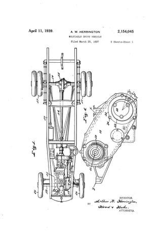
  • 1. April 11, 1939. A. w. HERRINGTON ' '. 2,154,045 MULTIAXLE DRIVE VEHICLE Filed March 25, 1937 2 Sheets-Sheet l INVENTOR. M v Wag,‘ . I ATTORNEYS.
  • 2. April 11, 1939- A. w. HERRINGTON 2,154,045 MULTIAXLE DRIVE VEHICLE Filed March 25, 195'? 2 Sheets-Sheet 2 INVENTOR. ATTORNEY-5. BY
  • 3. 40 Patented Apr. 11, 1939 UNITED STATES 2,154,645 PATENT OFFIQE 2,154,045 MULTIAXLE DRIVE VEHICLE Arthur W. Herrington, Indianapolis, Ind, as signor to Marmon-Herrington Company, Inc., Indianapolis, Ind., a. corporation of Indiana Application March 25, 5 Claims. The usual motor vehicle comprises a chassis frame supported at its front and rear ends upon axles which are in turn supported by wheels journaled upon the outer ends of the axles, and the vehicle is guided by swinging each of the front wheels about a substantially vertical axis. When such a vehicle is propelled through an arc-shaped path, the steering wheels always tra verse longer paths than the rear wheels and each outer wheel of each pair traverses a longer path than its companion inner wheel. This last-men tioned differential is compensated, as to wheel pairs to which power is applied, to one of many well known forms of differential gearing, and the ?rst~mentioned di?erential, as to non-powered wheels is of no consequence. In vehicles where more than one pair of pow ered traction wheels are provided, however, as in four-wheel drive structures, the first-mentioned 20 distance differential becomes a factor which re ‘sults in undue wear of the steering gear, tires, and an unnecessary consumption of power which cannot be compensated by the usual differential gears interposed between the power source and the transverse pairs of traction wheels. One of the objects of my invention is to provide mechanism by means of which delivery of power to the front power-driven wheels will be auto matically discontinued during arcuate travel and. automatically resumed during resumption of straight-line travel irrespective of whether the vehicle is being driven forwardly or rearwardly. A further object of my invention is to provide a structure, having the characteristics mentioned above, by means of which an ordinary two-wheel drive vehicle may be readily modi?ed to a four wheel drive vehicle, at low cost. A further object of my invention is to provide a structure, of the character mentioned above, wherein a driving chain forms one of the trans mission elements between the power plant and the front axle together with means by which lubrication for the drive train may be automati cally controlled in such manner that, while a thorough submersion lubrication will be provided for the chain in its initial operation, subsequent lubrication of the chain will be accomplished by mere surface contact between the chain and the lubricating pool, whereby objectionable heating of the lubricant will be avoided. In this connection attention is called to the fact that where a power» transmission chain is, in a portion of its run, submerged in lubricant, high speed movements of the chain through such a lubricating pool results in such heating of the 10 Q;61 45 55 1937, Serial No. 132,899 (Cl. 74—326) lubricant as to very seriously destroy its lubricat ing value. This is especially true with power transmission chains of the so—called roller type and one of the objects of my invention is. to pro vide means by which a power transmission chain 5 of the roller type, particularly, may be adequately lubricated but not over lubricated and the supply of lubricant will be protected against undue heat ing during the movement of the drive chain. A further object of my invention is to provide in convenient means by which adjustments may be made for variations in driving chain length with out disassembling the driving connection between the power plant and the front axle. The accompanying drawings illustrate my in_ vention: Fig. 1 is a plan of a vehicle in which my device has been. incorporated; Fig. 2 is an axial section of a unit capable of association with the rear end of the power de livery shaft of a speed varying transmission of common type to provide a chain driven power takeo? for connection with a driven steering wheel front axle structure (to be supplied) in place of the usual non-driven. steering wheel axle, the structure being such that the rear Wheel axle and associated propeller shaft may be utilized without chains; Fig. 3 is a section on line 3—3 of Fig. 2; and Fig. 4 is a side elevation of the structure shown in Fig. 3. In the drawings, l0 indicates the chassis frame, II the power plant, I2 the speed varying trans mission gearing provided with desirable control ling means and having a power delivery shaft I3, 3;, I4 the propeller shaft leading to the differential l5 of the rear axle 16 with its driven wheels ll, ll. A driven wheel front axle structure 18, with its differential l9, driven wheels 2!], 20, and propeller shaft 2| is to be substituted for the non-driven wheel front axle usually found in a rear-wheel drive vehicle. Shaft l3 of a standard speed varying trans mission is provided at its outer end with splines 28 for the non-rotative reception of one element of a common type of universal joint connection for‘ the rear wheel propeller shaft. In order to adapt such a structure for my present invention, I provide a splin-ed extension element i3’ which is secured to the outer end of shaft 13 by a bolt 2| threaded at 22 into the outer end of shaft I3; the splines at one end of element l3’ registering with the splines 20 of shaft l3. Splined upon splines 20 of shaft l3 and the registering splines of extension element I 3’ is a 15 55
  • 4. 10 15 20 25 30 35 40 45 50 75 2 sprocket wheel 22 preferably of the type for re ception of a roller type driving chain 23. Sup ported on shaft l3 and its extension by means of suitable bearings 25 and 23 is a casing 21 which forms a housing for the sprocket wheel 22, chain 23 and the parts now to be described. Casing 2? comprises ‘a cover element 28 through which the free end of extension l3’ projects so as to receive the universal coupling element 29, by means of which the power delivery shaft is con nected to the propeller shaft leading to the rear axle differential. The side plate of casing 21 and the cover plate 28 are respectively perforated with equal-diam eter aligned perforations 30 and 33’. Rotatably mounted in perforations 33’ is a bearing plate 3| supporting a bearing 32, the axis of which is eccentric to the axis of that portion of plate 3| which journals in perforation 30'. A hear ing plate 33 is journaled in perforation 33 and supports a bearing 34 alignable with bearing 32. Each of the bearing plates 3| and 33 is held in place by a retaining ring 35 held in place by suitable cap screws 36. In order to permit con venient access to bearing 34, plate 33 is provided with the bearing-receiving perforation 3'7 and this perforation is normally closed by a readily removable plate 38 held in place by cap screws 33. Each of plates 3| and 33 is provided with a peripheral series of teeth 40 and each retaining ring 35 is provided with a plurality of threaded openings 4| (say three) which are spaced apart differential distances somewhat greater than the pitch of teeth 40 so that by projecting a retaining screw 42 through a selected perforation 4| to project the inner end of said screw between an appropriate tooth pair of the bearing plate, said bearing plate may be selectively rotatively ad justed to vary the distance of the axes of bear ings 32 and 34 from the axis of shaft l3. Supported in the bearings 32 and 34 is a jack shaft 45, the forward end of which projects through bearing plate 3| to receive a standard coupling element 46 for ?exible connection with the propeller shaft which leads to the front axle differential. Keyed upon jack shaft 45 are two clutch ele ments 41, 41 each of which, on its inner face, is provided with ratchet clutch teeth 48, the teeth of one clutch element facing oppositely to the teeth of the other clutch element. Journaled and axially slidable upon jack shaft 45 between the clutch elements 41, 41 is a clutch element 49, the axial length of which is less than the distance between the tips of the two ratchet tooth series 48, 4B and the ends of which carry oppositely faced ratchet teeth series 50, 50 adapted to interdigitate with the adjacent ratchet teeth 48. The bore of clutch element 49 is pro vided with a peripheral groove 5| within which is mounted a split friction ring 52 and a radially acting spring 53 interposed between the external periphery of friction ring 52 and the bottom of groove 5| to establish a de?nite frictional en gagement of ring 52 with the periphery of jack shaft 45. Journaled upon the clutch elements Ail, 41 is a sprocket wheel 55 adapted to receive the chain 23. The bore of sprocket wheel 55 and the ex ternal periphery of clutch element 43 are pro vided with mating helical teeth 56, the arrange ment being such that relative rotation of clutch element 49 and sprocket wheel 55 will cause axial reciprocation of clutch element 49. 2,164,045 Casing 21 is supported at suitable points X and Y on the chassis frame. Formed in the lower part of casing 21 is an oil reservoir 65 separated by a dam 6! from that portion of the casing 21 in which sprocket wheel 55 rotates. Oil reservoir 60 is connected by one or more small bleed openings 62 vsn'th that por tion of the casing 21 within which sprocket wheel 55 rotates; said bleed openings being so propor tioned that, during normal running of chain 23, the. level of oil immediately adjacent sprocket wheel 55 will be approximately at the line 53 just touching chain 23 and the normal level of oil in reservoir 63 during that period will be approximately at line 34. After the parts have been at rest for some time, the oil levels in the two parts of the casing 2'! will be at an inter mediate point which will completely submerge a short section of chain 23 at its lowest point, the arrangement being such that the ?rst few turns of chain 23 will completely immerse the entire length of the chain in oil which will ultimately drain into reservoir 58 and there after, during continuous running, there will be an avoidance of submergence of the chain and there will be just enough surface contact of the chain with the oil in the lower part of the cas ing 27! to provide ample lubrication while at the same time preventing such churning of the oil by the movements of the chain as will result in undesirable heating of the oil. While the vehicle is moving forwardly in ap proximately a straight line clutch element 49 will be in one extreme axial position in clutching engagement with the adjacent clutch element 47 and upon reversal of movement of the vehicle there will be a relative rotation between sprocket wheel 55 and clutch element 49 (rotation of 49 on 45 being obstructed by the friction element 52) to cause axial shifting of the clutch element 49 to its opposite axial extreme. Whenever the steering wheels are tractively forwarded at a higher rate of speed than the rear driven wheels, in either direction of travel on the vehicle, there will be a relative rotation of the elements 55 and 49 suf?cient to cause the clutch element 49 to move to its intermediate position where its ratchet teeth are separated from both of the series of ratchet teeth 48, 48 and this condition will persist until the vehicle , is straightened out for straight-line travel where upon the clutch element 49 will be appropriately automatically shifted to one of its extreme po sitions to re-establish positive driving connection with the jack shaft 45. The structure described above makes possible a low-cost modi?cation of a standard two-wheel drive structure into a four-wheel drive struc ture, to produce a four-wheel drive structure which will automatically compensate for steer ing wheel rotations at higher speed than rear driving wheel rotations and which will provide for ample lubrication of the driving chain while at the same time insuring against undue oil heating. It will be readily understood that instead of the driving chain a meshing gear train between shafts l3 and 45 may be provided without departing from those portions of my invention other than the special lubrication control which, of course, may or may not be used. I claim as my invention: 1. A power transmission unit for motor ve hicles, comprising a hollow casing structure hav ing a bearing for the reception of a power deliv 5 10 20 25 30 35 40
  • 5. 10 15 20 80 55 2,154,045 ery shaft having a splined outer end, an exten sion for said power delivery shaft journaled in the casing in alignment with said bearing and having a splined inner end, means by which said exten sion may be rigidly attached to said power de livery shaft in alignment therewith, a rotary power transmitting element splined upon the in ner end of the extension shaft and splinable on the adjacent end of said power delivery shaft, a jack shaft journaled in said casing, a second ro tary power transmitting element associated with said jack shaft, and power transmitting means connecting said two rotary power transmitting elements. 4 2. A power transmission unit for motor vehicles, comprising a hollow casing structure having a bearing for the reception of a power delivery shaft, an extension for said power delivery shaft, means by which said extension may be attached to said power delivery shaft, a rotary power trans mitting element non-rotatably associated with said extension and non-rotatably associable with the end of said power delivery shaft, a jack shaft journaled in said casing, a second rotary power transmitting element associated with said jack shaft, power transmitting means connecting said two rotary power transmitting elements, a pair of ratchet tooth clutch elements carried by the jack shaft and having oppositely set ratchet teeth, a clutch element rotatably and slidably mounted upon the jack shaft between said clutch elements and having an overall length less than the dis tance between the ratchet teeth of said two clutch elements and having at its ends oppositely set ratchet teeth matable with the ratchet teeth of the adjacent ?rst-mentioned clutch elements, and a helical splined connection between said axially shiftable clutch element and the said second ro tary power transmitting element. 3. A power transmission unit comprising, a cas~ ing, a shaft journaled in one wall of the casing and projecting thereinto, a second shaft axially aligned with the ?rst shaft journalled in the op posite Wall of the casing and projecting thereinto, power-transmitting means connecting said two shafts for concurrent rotation, a third shaft journalled in one wall of said casing and project ing thereinto, two oppositely-set axially-spaced ratchet-toothed clutch elements non-rotatively associated with said third shaft within the cas ing, an intermediate clutch element rotatable and axially shiftable on said third shaft between said two oppositely-set clutch elements and having an overall length less than the distance between the teeth of said two clutch elements with oppositely set ratchet teeth at its two ends each toothed end being non-rotatively matable with one of said two clutch elements, a power-transmission ele ment driven by the ?rst-mentioned shaft and 3 sleeved over and housing said three clutch ele ments and rotatively interlocked with said inter mediate clutch element by helical interlocking ele ments such that relative rotation between said last-mentioned power-transmission element and said intermediate clutch element will produce axial movement of the intermediate clutch ele ment. 4. A power transmission unit comprising a casing, a primary shaft journaled therein, a sec ondary shaft journaled in said casing, two oppo sitely-faced ratchet-tooth clutch elements keyed ' to said secondary shaft, an axially shiftable clutch element journaled upon said secondary shaft be tween the ?rst-mentioned clutch elements and having an overall length less than the distance between said ?rst-mentioned clutch elements and having, at each end, ratchet teeth matable with the teeth of the adjacent clutch element, a fric tion element interposed between said axially shiftable clutch element and the secondary shaft to restrain relative rotation, a power transmis sion element sleeved over said clutch elements freely rotatable relative to the ?rst-mentioned clutch element by helical interlocking elements such that relative rotation between said power transmission element and said axially shiftable clutch element will produce axial movement of said axially shiftable clutch element, and driv~ ing connections between the ?rst-mentioned shaft and said rotary power transmitting element. 5. A power transmission unit comprising a cas ing, .a primary shaft journaled therein, a second ary shaft journaled in said casing, a pair of axially spaced ratchet-tooth clutch elements con nected to said secondary shaft and each having upon its inner face, ratchet teeth set oppositely to the teeth of the companion clutch element, a third clutch element rotatable and axially shift able upon said secondary shaft between the ?rst mentioned clutch elements and having an over all length of less than the distance between the ratchet teeth of said ?rst-mentioned clutch ele ments and having, at each end, ratchet tooth clutch elements matable with the adjacent clutch elements, a friction element interposed between said axially shiftable clutch element and the secondary shaft to restrain relative rotation, a rotary power transmitting element sleeved over and journaled upon the two ?rst-mentioned clutch elements, a helical splined connection be tween said third clutch element and said rotary power transmitting element whereby relative ro tation will produce axially shifting of said third clutch element, and driving connections between the ?rst-mentioned shaft and said rotary power transmitting element. ARTHUR W. HERRINGTON. 10 15 30 45 50 55