Downloaded 152 times

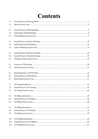
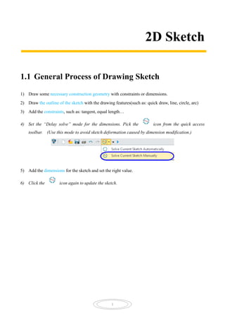
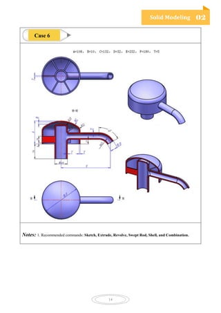
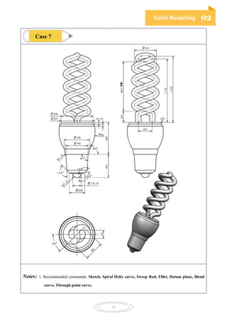
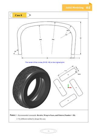
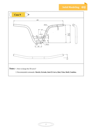
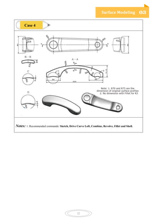
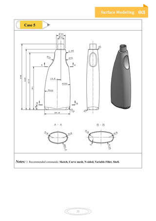
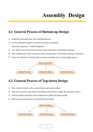
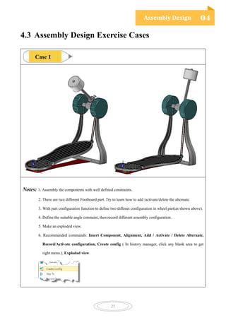


The document outlines various design processes and exercise cases for sketching, solid modeling, surface modeling, assembly design, mold design, and CNC machining using ZW3D software. It includes detailed steps for tasks such as creating 2D drawings, defining component relationships, and utilizing specific tools and commands for effective modeling. Additionally, it provides practical applications through exercise cases for each category to enhance user understanding and skills.