This document provides detailed installation instructions for the Construction Specialties 'ZB' series compression seals, emphasizing the importance of inspecting materials, following approved shop drawings, and ensuring proper surface preparation. Key steps include mixing and applying epoxy, securing the seal, and applying sealant to ensure a proper bond and minimize gaps. Additional notes cover specific procedures for splices, intersections, and maintenance of temperature requirements during installation.
![SEAL WIDTH
NOMINAL JOINT
WIDTH
3 1/2" [88.90mm] MAXIMUM
BLOCKOUT
3/4" ± 1/8"
[19.05mm ± 3.18mm]
BLOCKOUT
CAULK
EPOXY
EXPOSED SURFACE
Zip Block™ SEAL
Zip Block™ MODEL ZB-200 THRU ZB-400
INSTALLATION INSTRUCTIONS
CONSTRUCTION SPECIALTIES
IMPORTANT:
READ THROUGH ALL INSTRUCTIONS PRIOR TO STARTING INSTALLATION
Prior to the commencement of Installation all materials MUST be
inspected for Damage. Any damage must be reported to Construction
Specialties as soon as possible, so that replacement materials may be
furnished without delay.
All work must be completed as per Architect's Approved "Shop
Drawings", and in accordance with these Installation Instructions. When
installation is complete, all materials must be protected from damage
until the Architect's FINAL INSPECTION.
IMPORTANT
INFORMATION
P.O. BOX 380
FAX (570)-546-8022
PHONE (570)-546-5941
MUNCY, PA 17756
This document is the property of Construction Specialties and contains
CONFIDENTIAL PROPRIETARY INFORMATION that is not to be disclosed to
third parties and is not to be used without approval in writing from
Construction Specialties, Inc.
All materials should be arranged in the order that they
are to be installed. All hardware required for each portion
of the work should be placed with the appropriate
materials.
Please review all Approved Shop Drawings and this
Document to familiarize yourself with all the details and
components of this assembly.
12/03/07
12BT
ZB-200 ZB-300 ZB-400
EXPOSED SURFACE
SEAL WIDTH
NOMINAL JOINT WIDTH
9" [228.6mm]
8 1/2" [215.9mm]
2" [50.8mm]
10" [254.0mm]
9 1/2" [241.3mm]
3" [76.2mm]
11" [279.4mm]
10 1/2" [266.7mm]
4" [101.6mm]
Doc#: II-12BT Issue Date: 12/22/03 Rev Date: 12/03/07](https://image.slidesharecdn.com/zipblockinst-191028053238/85/Zipblock-inst-1-320.jpg)
![SEAL WIDTH
NOMINAL JOINT
WIDTH
3 1/2" [88.90mm] MAXIMUM
BLOCKOUT
3/4" ± 1/8"
[19.05mm ± 3.18mm]
BLOCKOUT
CAULK
EPOXY
EXPOSED SURFACE
Zip Block™ SEAL
Zip Block™ MODEL ZB-200 THRU ZB-400
INSTALLATION INSTRUCTIONS
CONSTRUCTION SPECIALTIES
IMPORTANT:
READ THROUGH ALL INSTRUCTIONS PRIOR TO STARTING INSTALLATION
Prior to the commencement of Installation all materials MUST be
inspected for Damage. Any damage must be reported to Construction
Specialties as soon as possible, so that replacement materials may be
furnished without delay.
All work must be completed as per Architect's Approved "Shop
Drawings", and in accordance with these Installation Instructions. When
installation is complete, all materials must be protected from damage
until the Architect's FINAL INSPECTION.
IMPORTANT
INFORMATION
P.O. BOX 380
FAX (570)-546-8022
PHONE (570)-546-5941
MUNCY, PA 17756
This document is the property of Construction Specialties and contains
CONFIDENTIAL PROPRIETARY INFORMATION that is not to be disclosed to
third parties and is not to be used without approval in writing from
Construction Specialties, Inc.
All materials should be arranged in the order that they
are to be installed. All hardware required for each portion
of the work should be placed with the appropriate
materials.
Please review all Approved Shop Drawings and this
Document to familiarize yourself with all the details and
components of this assembly.
12/03/07
12BT
ZB-200 ZB-300 ZB-400
EXPOSED SURFACE
SEAL WIDTH
NOMINAL JOINT WIDTH
9" [228.6mm]
8 1/2" [215.9mm]
2" [50.8mm]
10" [254.0mm]
9 1/2" [241.3mm]
3" [76.2mm]
11" [279.4mm]
10 1/2" [266.7mm]
4" [101.6mm]
Doc#: II-12BT Issue Date: 12/22/03 Rev Date: 12/03/07](https://image.slidesharecdn.com/zipblockinst-191028053238/75/Zipblock-inst-1-2048.jpg)
![3 1/2" [88.90mm] MIN.
BLOCKOUT
NOMINAL JOINT
WIDTH
3/4"±1/8" [19.05mm±3.18mm]
BLOCKOUT
SANDBLAST THESE SURFACES
1. Before beginning installation of the ZB seal, review the layouts for the various runs of seal as detailed on the
approved Construction Specialties shop drawings.
2. The "ZB" series compression seals must be securely mounted to structurally sound concrete that has cured for at
least 7 days. Repair all damage to the blockouts before beginning installation.
3. The blockouts in which the ZB seal is to be mounted must be flat, level and parallel. The base of the blockout must
be flat (along the length of the joint) to within +/-1/8" [3.18mm] and level (across the joint) to within +/-1/8" [3.18mm].
4. The blockout width shown on the Construction Specialties shop drawings is a minimum width dimension. The
blockout may be made up to 1/4" [6.35mm] wider to allow for greater installation tolerance.
5. The blockout surfaces must be sandblasted to expose new concrete and remove all form release agents and other
foreign materials.
6. The surface of the blockouts must be clean and free from any loose dust, dirt, debris and oils that would affect the
installation of the seal, or adhesion of the epoxy.
7. Refer to the Construction Specialties Expansion Joint Tech Manual for proper joint width at time of seal installation.
8. All splices and transitions must be cut square and smooth to ensure a good seal.
9. When cutting the seal for any transitions, the cell must be compressed to the installed joint size (nominal size) to
match up properly when installed.
GENERAL NOTES:
PAGE 2
Doc#: II-12BT Issue Date: 12/22/03 Rev Date: 12/03/07](https://image.slidesharecdn.com/zipblockinst-191028053238/85/Zipblock-inst-2-320.jpg)
![WIRE BRUSHWIRE BRUSH
1.1) Unroll each length of compression seal and lay each one upside-down on a flat surface.
1.2) Wire brush the bottom and sides of the wings and sides of the compression area thoroughly using a drill or grinder
with a wire wheel mounted in the chuck. All of the wire brushed areas should have a dull black appearance when
finished. There should be no gloss or white residue left on these surfaces. The epoxy may not bond properly if the
seal is not thoroughly wire brushed.
1.3) Clean the seal thoroughly using compressed air to remove any loose rubber particles left behind from the wire brush.
PREPARE SEAL
STEP 1
PAGE 3
PREPARE SEAL FOR SPLICES
STEP 2
2.1) Before applying sealant use a wire brush (see detail above) or heavy sandpaper to create a rough surface on the
seal approx. 2" [50.80mm] from the edge. Be sure to sand the sides and bottoms of the V-grooves as much as
possible. This will ensure that the surface and sealant have a better bond. Wire brushed areas should have a dull
black appearance when finished. Clean the seal thoroughly using compressed air to remove any loose rubber
particles left behind from the wire brush.
2.2) Install compressible foam in ends at this point.
Step 2.1 Step 2.2
FOAM
Doc#: II-12BT Issue Date: 12/22/03 Rev Date: 12/03/07](https://image.slidesharecdn.com/zipblockinst-191028053238/85/Zipblock-inst-3-320.jpg)
![APPLY A LAYER OF
EPOXY
APPROXIMATELY
1/16"[1.59mm] -
1/8"[3.18mm] THICK
PLACE ONE WING IN BLOCKOUT
STEP 3
BEGIN INSTALLATION
*IMPORTANT NOTE: Do not use epoxy or install this seal if either the substrate temperature or air temperature will drop below 40°F
(5°C) during the installation or cure time of 8 hours.
3.1) Place each length of seal upside-down next to the blockout area where it is to be installed. This will allow the seal some time to
flatten before it is bonded in place.
3.2) Check to ensure that the concrete blockouts are free from loose dirt, debris and oils. It is critical that the blockouts are clean to
allow the epoxy to achieve the proper bond.
3.3) Mix the Construction Specialties supplied, 2 component epoxy. Measure equal amounts of Part A and Part B by volume. Pour
both Part A and Part B into a container and mix thoroughly for three minutes until a uniform gray color is achieved. Do not mix in
direct sunlight as this will decrease the work life of the epoxy. Only mix the amount of epoxy that can be used within its gel time
(see chart for gel time based on temperature).
3.4) Apply the epoxy by loading it into a bulk gun and ejecting it into the blockout area. Spread the epoxy with a trowel until it is
approximately 1/16"[1.59mm] - 1/8"[3.18mm] thick. Apply epoxy approximately 1 1/2"[38.1mm] down the vertical face of the joint.
The epoxy must be applied quickly to allow time for the seal to be installed before it begins to gel. Once the epoxy has begun to
gel or get hot, a proper bond will not be achieved.
85(29.44)
70(21.11)
TEMP
50(10)
WORK LIFE
35 MINUTES
°F (°C)
25 MINUTES
20 MINUTES
APPROXIMATE WORK LIFE OF
EPOXY
3.5) Place the first section of seal into the blockout area. Place the wing on one side of the seal into the blockout.
3.6) Ensure that the seal is in the correct position along the length of the joint.
PAGE 4
Doc#: II-12BT Issue Date: 12/22/03 Rev Date: 12/03/07](https://image.slidesharecdn.com/zipblockinst-191028053238/85/Zipblock-inst-4-320.jpg)
![SAND BAG
2" X 8" BOARD
APPLY CAULK AFTER
PLACING WEIGHT ON SEAL
STEP 4
INSTALL SEAL IN JOINT
4.1) Starting at one end of the seal, lift the wing that was not previously seated in the blockout and push inward on the compression seal
using a shaft (3/4"[19.05mm] plywood, metal bar stock, etc.). As you push inward on the compression seal every few inches, have
someone follow behind you walking on the seal to seat it into place.
4.2) Place 2"[50.80mm] X 8"[203.2mm] boards on the compression seal the entire length of the seal.
4.3) Place sand bags, or something of similar weight, every couple feet on top of the boards. This will force the seal to seat into the
epoxy during the cure cycle.
4.4) Allow the weights and boards to remain on the seal for approximately 8 hours.
4.5) Apply the Construction Specialties supplied caulk to the edge of the seal. This step can be performed as each section of seal is
placed, or after the entire run of seal has been installed, as outlined in Step 12.
It is recommended to caulk the edge after each section of seal is placed to prevent dirt and debris from entering the gap at the seal edge.
PAGE 5
Doc#: II-12BT Issue Date: 12/22/03 Rev Date: 12/03/07](https://image.slidesharecdn.com/zipblockinst-191028053238/85/Zipblock-inst-5-320.jpg)
![APPLY CONSTRUCTION SPECIALTIES
SUPPLIED SEALANT TO
FACE OF INSTALLED SEAL
LOOSE SEAL
ALIGNMENT DOWELS PRESSED
INTO INSTALLED SEAL
FOAM
STEP 5
SPLICES
5.1) Ensure that the ends of the next seal to be installed are cut square and clean.
5.2) Apply the Construction Specialties supplied contact cement to a dowel and place it in the oval slot of the installed seal. Repeat this
step until you have placed 4 dowels as shown in the figure above.
5.3) Cut and place the Construction Specialties supplied foam into the cells of the seals as shown above.
5.4) Apply the Construction Specialties supplied Sealant to the end of the previously installed section of seal.
5.5) Follow Step 3 to mix and apply the epoxy to the blockout area of the next section of joint.
5.6) Place the end of the next section of seal in the blockout and press the first 5-6 inches [127mm-152.4mm] of the seal into the joint
to align the alignment pins with the end of the previously installed section.
5.7) Slide the seal against the end of the installed section so that the alignment pins slide into the corresponding cells. Ensure that
there is not a gap between the ends of the seals.
5.8) Place remaining length of seal in the blockout and install according to Steps 3 and 4.
PAGE 6
Doc#: II-12BT Issue Date: 12/22/03 Rev Date: 12/03/07](https://image.slidesharecdn.com/zipblockinst-191028053238/85/Zipblock-inst-6-320.jpg)
![STEP 5 (Cont.)
SPLICES
5.9) Apply 2"[50.80mm] wide masking tape along the top surface of the seal approx. 2"[50.80mm] away from joint splice. The tape
should be applied on both sides of the joint splice and both sides of the joint.
5.10) Apply the Construction Specialties supplied Sealant into the base of the V's, filling the V's and any other voids.
5.11) Apply the Construction Specialties supplied Sealant across the seal in a zigzag pattern crossing the splice. Apply sufficient
amounts of Sealant to seal to create, when smoothed out, an approx. thickness of 1/8 "[3.18mm] to 3/16"[4.76mm].
PAGE 7
Step 5.9
Step 5.11
MASKING TAPE
SPLICE LOCATION
MASKING TAPE
SEALANT
SPLICE LOCATION
Doc#: II-12BT Issue Date: 12/22/03 Rev Date: 12/03/07](https://image.slidesharecdn.com/zipblockinst-191028053238/85/Zipblock-inst-7-320.jpg)
![STEP 5 (Cont.)
SPLICES
PAGE 8
Step 5.12
5.12) Use a putty knife to smooth out the Construction Specialties supplied Sealant evenly over the entire width of the seal.
5.13) Use a clean putty knife to separate the sealant between the V's. This will allow the seal to move without tearing the Sealant apart.
Be careful not to separate too deep into the V's. Sealant should be approx. 1/8"[50.80mm] on bottom and sides of the V's. After
separating the V's, make sure that you smooth out the edges of the sealant and remove the tape.
5.14) Place the Construction Specialties supplied pieces of 2"[50.8"] x 6"[152.4mm] polyethylene strips into the V's to prevent them from
sticking together during cure time.
5.15) Allow the Sealant to cure for 24-48 hours (depending on temperature) keeping all vehicles away from the splice and minimizing the
amount of movement of the seal.
Step 5.13
Step 5.13 Step 5.14
SEALANT
TAPE
SEALANT
TAPE
PUTTY KNIFE
TAPE
SEALANT SEALANT
POLYETHYLENE
STRIPS
Doc#: II-12BT Issue Date: 12/22/03 Rev Date: 12/03/07](https://image.slidesharecdn.com/zipblockinst-191028053238/85/Zipblock-inst-8-320.jpg)
![MITER CUT SEAL
INSTALL 90° ALIGNMENT PINS
W/ CONSTRUCTION SPECIALTIES
SUPPLIED CONTACT CEMENT
APPLY CONSTRUCTION SPECIALTIES
SUPPLIED SEALANT TO CUT
SURFACES OF SEAL
CONSTRUCTION SPECIALTIES
SUPPLIED SEALANT
POLYETHYLENE STRIPS
STEP 6
ANGLED INTERSECTION
6.1) Miter the ends of the seals to the proper angle while compressed to the proper joint width.
6.2) Install the first section of seal according to Steps 1 through 5. Ensure that the miter cut end is at the proper location.
6.3) Install the 90° alignment pins with the Construction Specialties supplied contact cement in the end of the installed seal.
6.4) Apply the Construction Specialties supplied Sealant to the cut end of the installed seal.
6.5) Follow Step 3 to mix and apply the epoxy to the blockout area of the next section of joint.
6.6) Place the end of the next section of seal in the blockout and press the first 5-6 inches [127mm-152.4mm] of the seal into the joint to
align with the alignment pins in the previously installed section.
6.7) Slide the seal against the end of the installed section so that the alignment pins slide into the corresponding cells. Ensure that there is
not a gap between the ends of the seals.
6.8) Place the remaining length of seal in the blockout and install according to Steps 3 and 4.
6.9) Apply more Construction Specialties supplied Sealant over the top of the splice in accordance with Step 5.
PAGE 9
Doc#: II-12BT Issue Date: 12/22/03 Rev Date: 12/03/07](https://image.slidesharecdn.com/zipblockinst-191028053238/85/Zipblock-inst-9-320.jpg)
![V-CUT (90°) MAIN RUN OF SEAL
APPLY CONSTRUCTION SPECIALTIES
SUPPLIED SEALANT TO
THE CUT SURFACES
INSTALL 90° ALIGNMENT PINS
W/ CONSTRUCTION SPECIALTIES
SUPPLIED CONTACT CEMENT
CONSTRUCTION
SPECIALTIES
SUPPLIED
SEALANT
POLYETHYLENE
STRIPS
STEP 7
T-INTERSECTION
7.1) Butt two runs of adjoining seals together at the center of the intersecting joint.
7.2) Make a 45° cut through half the adjoining seals while compressed to the proper joint width as shown above.
7.3) Apply Construction Specialties supplied Sealant to cut ends of the seals.
7.4) Slide the seal against the previously installed seal so that the alignment pins slide into the corresponding cells. Ensure that there is
not a gap between the seals.
7.5) V-cut the end of the mating seal so that both seals will fit together properly.
7.6) Install the 90° alignment pins with the Construction Specialties supplied contact cement in the end of the installed seal.
7.7) Apply the Construction Specialties supplied Sealant to the cut end of the installed seal.
7.8) Follow Step 3 to mix and apply the epoxy to the blockout area of the next section of joint.
7.9) Place the end of the next section of seal in the blockout and press the first 5-6 inches [127mm-152.4mm] of the seal into the joint to
align with the alignment pins in the previously installed section.
7.10) Slide the seal against the V-cut of the installed section so that the alignment pins slide into the corresponding cells. Ensure that
there is not a gap between the seals.
7.11) Place the remaining length of seal in the blockout and install according to Steps 3 and 4.
7.12) Apply more Construction Specialties supplied Sealant over the top of the splice in accordance with Step 5.
PAGE 10
Doc#: II-12BT Issue Date: 12/22/03 Rev Date: 12/03/07](https://image.slidesharecdn.com/zipblockinst-191028053238/85/Zipblock-inst-10-320.jpg)
![V-CUT (90°) EACH SIDE
INSTALL 90° ALIGNMENT PINS
W/ CONSTRUCTION SPECIALTIES
SUPPLIED CONTACT CEMENT
CONSTRUCTION
SPECIALTIES
SUPPLIED
SEALANTPOLYETHYLENE
STRIPS
STEP 8
CROSS INTERSECTION
8.1) V-cut each side of the main run of seal at the joint intersection while
compressed to proper joint width as shown above.
8.2) V-cut the ends of the mating sections of seal to allow them to fit properly with the main run.
8.3) Install the 90° alignment pins with the Construction Specialties supplied contact cement in the V-cuts of the main run of seal.
8.4) Apply the Construction Specialties supplied Sealant to the cut end of the installed seal.
8.5) Mix the epoxy and apply it to the blockout areas as outlined in Step 3.
8.6) Place the end of the next section of seal in the blockout and press the first 5-6 inches [127mm-152.4mm] of the seal into the joint to
align with the alignment pins in the previously installed section.
8.7) Slide the seal against the end of the installed section so that the alignment pins slide into the corresponding cells. Ensure that there
is not a gap between the ends of the seals.
8.8) Place the remaining length of seal in the blockout and install according to Steps 3 and 4.
8.10) Repeat the above steps to install the opposite side of the cross intersection.
8.11) Apply more Construction Specialties supplied Sealant over the top of the splice in accordance with Step 5.
PAGE 11
Doc#: II-12BT Issue Date: 12/22/03 Rev Date: 12/03/07](https://image.slidesharecdn.com/zipblockinst-191028053238/85/Zipblock-inst-11-320.jpg)
![MITER CUT SEAL AND APPLY
CONSTRUCTION SPECIALTIES
SUPPLIED SEALANT TO
THE CUT SURFACES
INSTALL 90° ALIGNMENT PINS
W/ CONSTRUCTION SPECIALTIES
SUPPLIED CONTACT CEMENT
CONSTRUCTION
SPECIALTIES
SUPPLIED
SEALANT
POLYETHYLENE
STRIPS
STEP 9
VERTICAL TRANSITION
9.1) Miter cut the ends of the mating sections of seal.
9.2) Install 90° alignment pins in the bottom horizontal section of seal using the Construction Specialties supplied contact cement.
9.3) Install the bottom horizontal run of seal following Steps 1 through 4. Ensure that the mitered end of the seal is located properly in
the blockout.
9.4) Apply the Construction Specialties supplied Sealant to the cut end of the seal.
9.5) Mix the epoxy and apply it to the vertical blockout areas as outlined in Step 3.
9.6) Install the vertical run of seal in the blockout following Steps 1 through 4. Ensure that the alignment pins are properly seated
within the corresponding cells.
9.7) Apply more Construction Specialties supplied Sealant over the top of the splice.
9.8) Install 90° alignment pins in the top of the vertical seal using the Construction Specialties supplied contact cement.
9.9) Apply the Construction Specialties supplied Sealant to the cut end of the vertical seal.
9.10) Mix the epoxy and apply it to the top horizontal blockout areas as outlined in Step 3.
9.11) Place the end of the top horizontal section of seal in the blockout and press the first 5-6 inches [127mm-152.4mm] of the seal into
the joint to align with the alignment pins in the previously installed section.
9.12) Slide the seal against the end of the installed section so that the alignment pins slide into the corresponding cells. Ensure that
there is not a gap between the ends of the seals.
9.13) Place the remaining length of seal in the blockout and install according to Steps 3 and 4.
9.14) Apply more Construction Specialties supplied Sealant over the top of the splices in accordance with Step 5.
PAGE 12
Doc#: II-12BT Issue Date: 12/22/03 Rev Date: 12/03/07](https://image.slidesharecdn.com/zipblockinst-191028053238/85/Zipblock-inst-12-320.jpg)
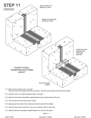
![CUT WING AT WALL
INTERSECTION
FLIP WING UPWARD
AND ANCHOR TO
WALL WITH EPOXY
SUPPORT PLATE
RECOMMENDED
FOR LENGTHS
OVER 3 FEET
REMOVE WING
STEP 10
TRANSITIONS
STEP 10:
10.1) Cut through the width of the wing in the location where the seal will intersect a wall. Also, use a utility knife to cut the seal wall
from the wing on the section to be flipped upward.
10.2) Install the run of seal according to Steps 1 through 5. Ensure that the cut sections of wing are flipped upward at the wall
locations.
10.3) Apply epoxy to the face of the wall where the wing will be located.
10.4) Place a weight, 4x4 [101.6mm x 101.6mm] lumber or equivalent object against the vertical wing to hold it in place until the epoxy
cures.
STEP 10A (RECOMMENDED OPTION):
10A.1) If using a support plate, install it using the Construction Specialties supplied fasteners.
10A.2) Remove the sections of wing where the seal will intersect a wall.
10A.3) Install the seal according to steps 1 through 5. Be sure to apply epoxy to the vertical face of the support plate to ensure the
seal is bonded.
FLOOR TO WALL
TRANSITION WITH WING
INTACT
FLOOR TO WALL
TRANSITION WITH WING
REMOVED
(RECOMMENDED)
CUT SEAL WALL FROM WING
PAGE 13
END VIEW
END VIEW
Doc#: II-12BT Issue Date: 12/22/03 Rev Date: 12/03/07](https://image.slidesharecdn.com/zipblockinst-191028053238/85/Zipblock-inst-13-320.jpg)