Download to read offline
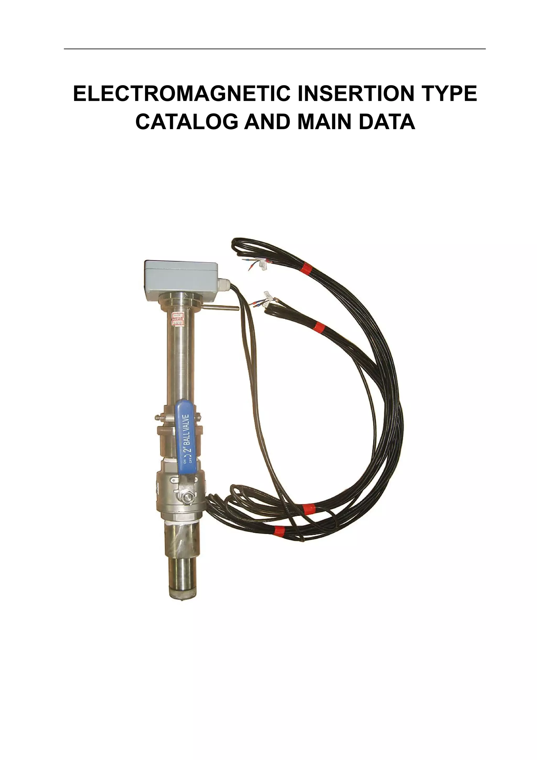


1. This document provides specifications for an electromagnetic insertion type flow meter. 2. Key features include measurement accuracy unaffected by fluid properties, minimum straight pipe requirements, wide pipe size range, low power consumption, and digital communication interfaces. 3. The flow meter can measure flow rates from 0-15m/s in pipes from 6mm to 2000mm diameter, covering applications in chemical, oil, water, and other industries.