Download to read offline
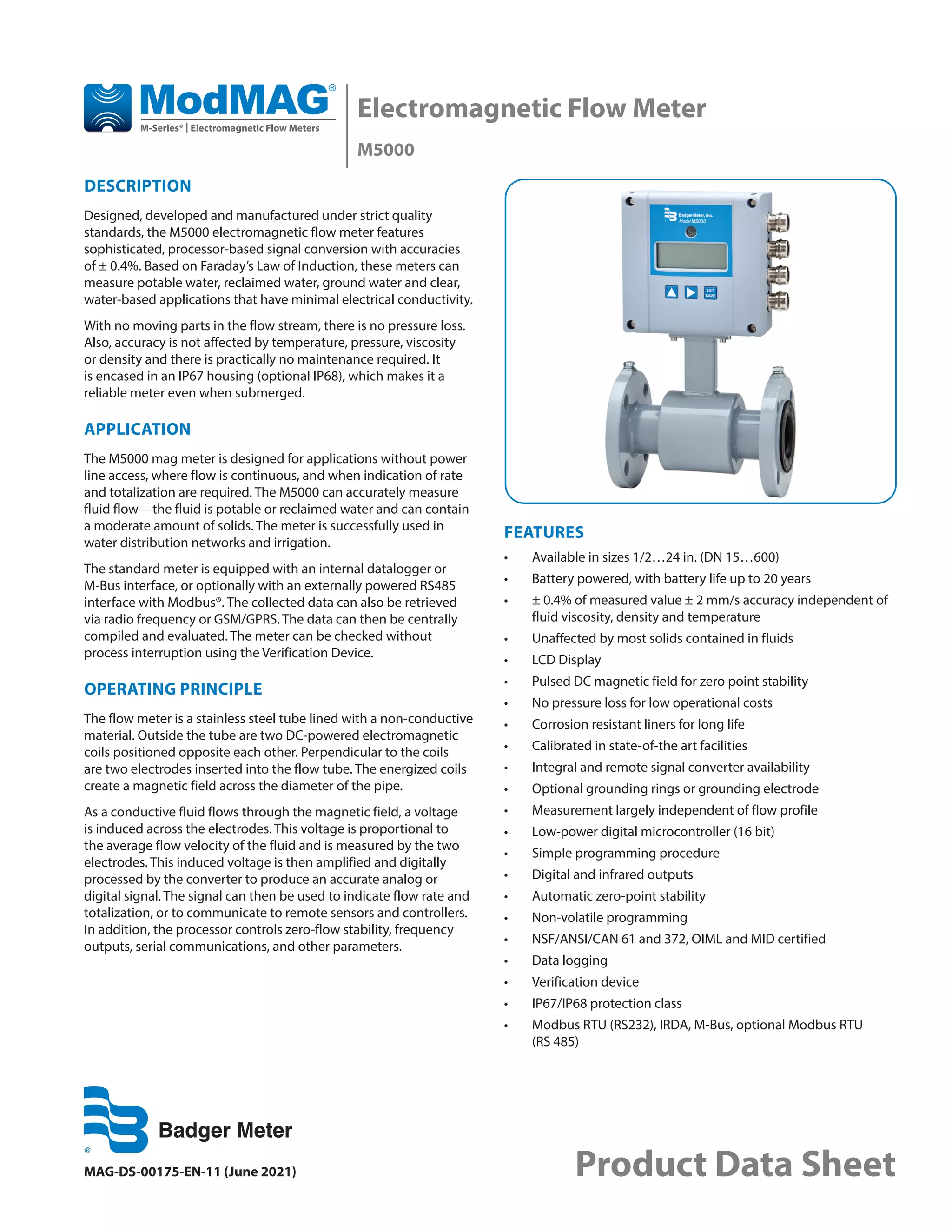

The M5000 electromagnetic flow meter is a high-accuracy device designed for measuring potable and reclaimed water in various applications without power line access, offering an accuracy of ± 0.4%. It features a maintenance-free design with no moving parts, allowing for consistent performance unaffected by changing fluid properties. The flow meter is available in various sizes and configurations, equipped with data logging capabilities and several communication options, making it suitable for water distribution and irrigation networks.


![[Envimart's Products] Đồng hồ điện từ đo lưu lượng nước, MagFlux hãng MJK](https://cdn.slidesharecdn.com/ss_thumbnails/en-305-magflux-datasheet-1711-190216143317-thumbnail.jpg?width=640&height=640&fit=bounds)


