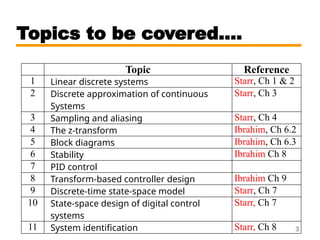
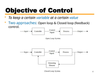
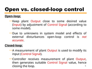
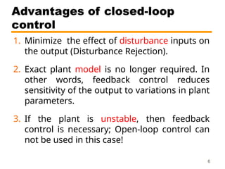
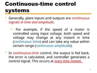
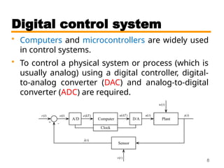
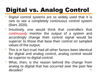
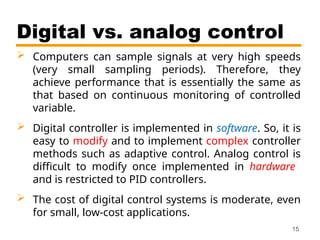
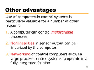
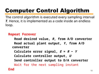
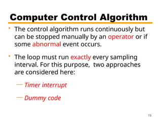
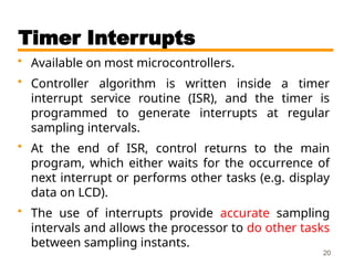
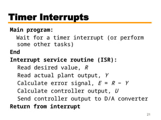
Introduction
CSE 421 Digital Control
Lecture 1
1
Grading scheme
50 Semester work
100 Final
150 Total
References:
1. Starr, G. Introduction to Applied Digital Controls, Springer 2020.
2. Ibrahim, D., Microcontroller Based Applied Digital Control. Wiley,
2006.
3. Philips, D., Nagle, H. and Chakrabortty, A., Digital Control
System Analysis and Design, 4th Edition, Pearson, 2015.
Course webpage:
http://www.amelanany.faculty.zu.edu.eg/
2
Topics to be covered….
Topic Reference
1 Linear discrete systems Starr, Ch 1 & 2
2 Discrete approximation of continuous
Systems
Starr, Ch 3
3 Sampling and aliasing Starr, Ch 4
4 The z-transform Ibrahim, Ch 6.2
5 Block diagrams Ibrahim, Ch 6.3
6 Stability Ibrahim Ch 8
7 PID control
8 Transform-based controller design Ibrahim Ch 9
9 Discrete-time state-space model Starr, Ch 7
10 State-space design of digital control
systems
Starr, Ch 7
11 System identification Starr, Ch 8 3
Objective of Control
• To keep a certain variable at a certain value
4
• Two approaches: Open loop & Closed loop (feedback)
control.
Open-loop:
—Keep plant Output close to some desired value
(Input) by adjustment of Control Signal (according to
some model).
—Due to unknowns in system model and effects of
external disturbances open-loop control is not
accurate.
Closed-loop:
—A measurement of plant Output is used to modify its
input (Control Signal).
—Controller receives measurement of plant Output,
then generates suitable Control Signal value, hence
closing the loop.
Open vs. closed-loop control
5
Advantages of closed-loop
control
1. Minimize the effect of disturbance inputs on
the output (Disturbance Rejection).
2. Exact plant model is no longer required. In
other words, feedback control reduces
sensitivity of the output to variations in plant
parameters.
3. If the plant is unstable, then feedback
control is necessary; Open-loop control can
not be used in this case!
6
Continuous-time control
systems
• Generally, plant inputs and outputs are continuous
signals in time and amplitude.
— For example, if the speed of a motor is
controlled using input voltage, both speed and
voltage may change at any instant in time
(continuous time) and can take any value within
certain range (continuous amplitude).
• In continuous-time control, the output is fed back,
the error is calculated, and controller generates a
control signal. This occurs at every time instant.
7
Digital control system
• Computers and microcontrollers are widely used
in control systems.
• To control a physical system or process (which is
usually analog) using a digital controller, digital-
to-analog converter (DAC) and analog-to-digital
converter (ADC) are required.
8
Sampling
• The computer periodically samples the error signal
every interval T called the sampling period. This is
the role of the clock in the block diagram (in slide
8).
• The sampling frequency in Hz is 1/T.
• When a continuous signal e(t) is sampled, it
becomes a discrete sequence denoted by e(kT),
e(k) or ek.
• Discrete signals are mathematically defined only at
the sample instants t = kT, where k = 0,1,2,….
• Digital control systems are also called discrete-time9
Analog-to-digital (A/D) converter
• A/D converter samples analog signal (typically
voltage), and converts the sample value into
integer number (binary) suitable for processing
by digital computer.
• The A/D converter is approximated as a sampler
(a switch).
10
A/D converter
• A/Ds typically have unipolar ranges of 0–5V, 0–
10V, or bipolar ranges of ± 5V, or ± 10V.
• A/D conversion causes quantization error q which
depends on the resolution of the converter in
bits.
• Common resolutions are 8 bits (256 levels), and
12 bits (4096 levels).
• A 12-bit A/D of range ±10 volts would have a
conversion quantum of q = 20/4096 = 4.88 mV.
11
Digital-to-analog (D/A) converter
• D/A converts a digital (integer) number
calculated by the computer into a voltage so as
to drive the plant.
• The voltage ranges and converter resolutions
are the same as for the A/D converter.
• D/A converter functions as a zero-order hold
(ZOH), holding its output at a constant value
until it receives the next discrete input.
• Many microcontrollers incorporate built-in A/D
and D/A converter circuits. Hence, they can be
connected directly to analog signals.
12
Continuous, discrete, and
ZOH (output of D/A) signals
13
Digital vs. Analog Control
• Digital control systems are so widely used that it is
rare to see a completely continuous control system
(Starr, 2020).
• Intuitively, one would think that controllers that
continuously monitor the output of a system and
accordingly change their control signal would be
superior to those that base their control on sampled
values of the output.
• This is in fact true! Had all other factors been identical
for digital and analog control, analog control would
be superior to digital control.
• What, then, is the reason behind the change from
analog to digital that has occurred over the past few
decades? 14
Digital vs. analog control
 Computers can sample signals at very high speeds
(very small sampling periods). Therefore, they
achieve performance that is essentially the same as
that based on continuous monitoring of controlled
variable.
 Digital controller is implemented in software. So, it is
easy to modify and to implement complex controller
methods such as adaptive control. Analog control is
difficult to modify once implemented in hardware
and is restricted to PID controllers.
 The cost of digital control systems is moderate, even
for small, low-cost applications.
15
Other advantages
Use of computers in control systems is
particularly valuable for a number of other
reasons:
1. A computer can control multivariable
processes.
2. Nonlinearities in sensor output can be
linearized by the computer.
3. Networking of control computers allows a
large process-control systems to operate in a
fully integrated fashion.
16
Computer Control Algorithm
In order to use a computer to control a given system,
it must execute the following algorithm:
1. Read desired value, R, from A/D converter
2. Read actual plant output, Y, from A/D
converter
3. Calculate error signal, E = R − Y
4. Calculate the controller output, U
5. Send controller output to D/A converter
17
Computer Control Algorithm
The control algorithm is executed every sampling interval
T. Hence, it is implemented as a code inside an endless
loop.
Repeat Forever
Read desired value, R, from A/D converter
Read actual plant output, Y, from A/D
converter
Calculate error signal, E = R − Y
Calculate controller output, U
Send controller output to D/A converter
Wait for the next sampling instant
End 18
Computer Control Algorithm
• The control algorithm runs continuously but
can be stopped manually by an operator or if
some abnormal event occurs.
• The loop must run exactly every sampling
interval. For this purpose, two approaches
are considered here:
— Timer interrupt
— Dummy code
19
Timer Interrupts
• Available on most microcontrollers.
• Controller algorithm is written inside a timer
interrupt service routine (ISR), and the timer is
programmed to generate interrupts at regular
sampling intervals.
• At the end of ISR, control returns to the main
program, which either waits for the occurrence of
next interrupt or performs other tasks (e.g. display
data on LCD).
• The use of interrupts provide accurate sampling
intervals and allows the processor to do other tasks
between sampling instants.
20
Timer Interrupts
Main program:
Wait for a timer interrupt (or perform
some other tasks)
End
Interrupt service routine (ISR):
Read desired value, R
Read actual plant output, Y
Calculate error signal, E = R − Y
Calculate controller output, U
Send controller output to D/A converter
Return from interrupt
21
Dummy Code
• This is based on a simple idea: Find execution time of
instructions inside loop and add dummy code to adjust loop
execution time so that it equals the required sampling
interval.
Do Forever:
Read desired value, R
Read actual plant output, Y
Calculate error signal, E = R − Y
Calculate controller output, U
Send controller output to D/A converter
Dummy code
End
• Problem: If the code inside the loop or CPU clock change, it
will be necessary to readjust the dummy code ► not accurate22

Zagazig digital control introduction.pptx

  • 1.
    Introduction CSE 421 DigitalControl Lecture 1 1
  • 2.
    Grading scheme 50 Semesterwork 100 Final 150 Total References: 1. Starr, G. Introduction to Applied Digital Controls, Springer 2020. 2. Ibrahim, D., Microcontroller Based Applied Digital Control. Wiley, 2006. 3. Philips, D., Nagle, H. and Chakrabortty, A., Digital Control System Analysis and Design, 4th Edition, Pearson, 2015. Course webpage: http://www.amelanany.faculty.zu.edu.eg/ 2
  • 3.
    Topics to becovered…. Topic Reference 1 Linear discrete systems Starr, Ch 1 & 2 2 Discrete approximation of continuous Systems Starr, Ch 3 3 Sampling and aliasing Starr, Ch 4 4 The z-transform Ibrahim, Ch 6.2 5 Block diagrams Ibrahim, Ch 6.3 6 Stability Ibrahim Ch 8 7 PID control 8 Transform-based controller design Ibrahim Ch 9 9 Discrete-time state-space model Starr, Ch 7 10 State-space design of digital control systems Starr, Ch 7 11 System identification Starr, Ch 8 3
  • 4.
    Objective of Control •To keep a certain variable at a certain value 4 • Two approaches: Open loop & Closed loop (feedback) control.
  • 5.
    Open-loop: —Keep plant Outputclose to some desired value (Input) by adjustment of Control Signal (according to some model). —Due to unknowns in system model and effects of external disturbances open-loop control is not accurate. Closed-loop: —A measurement of plant Output is used to modify its input (Control Signal). —Controller receives measurement of plant Output, then generates suitable Control Signal value, hence closing the loop. Open vs. closed-loop control 5
  • 6.
    Advantages of closed-loop control 1.Minimize the effect of disturbance inputs on the output (Disturbance Rejection). 2. Exact plant model is no longer required. In other words, feedback control reduces sensitivity of the output to variations in plant parameters. 3. If the plant is unstable, then feedback control is necessary; Open-loop control can not be used in this case! 6
  • 7.
    Continuous-time control systems • Generally,plant inputs and outputs are continuous signals in time and amplitude. — For example, if the speed of a motor is controlled using input voltage, both speed and voltage may change at any instant in time (continuous time) and can take any value within certain range (continuous amplitude). • In continuous-time control, the output is fed back, the error is calculated, and controller generates a control signal. This occurs at every time instant. 7
  • 8.
    Digital control system •Computers and microcontrollers are widely used in control systems. • To control a physical system or process (which is usually analog) using a digital controller, digital- to-analog converter (DAC) and analog-to-digital converter (ADC) are required. 8
  • 9.
    Sampling • The computerperiodically samples the error signal every interval T called the sampling period. This is the role of the clock in the block diagram (in slide 8). • The sampling frequency in Hz is 1/T. • When a continuous signal e(t) is sampled, it becomes a discrete sequence denoted by e(kT), e(k) or ek. • Discrete signals are mathematically defined only at the sample instants t = kT, where k = 0,1,2,…. • Digital control systems are also called discrete-time9
  • 10.
    Analog-to-digital (A/D) converter •A/D converter samples analog signal (typically voltage), and converts the sample value into integer number (binary) suitable for processing by digital computer. • The A/D converter is approximated as a sampler (a switch). 10
  • 11.
    A/D converter • A/Dstypically have unipolar ranges of 0–5V, 0– 10V, or bipolar ranges of ± 5V, or ± 10V. • A/D conversion causes quantization error q which depends on the resolution of the converter in bits. • Common resolutions are 8 bits (256 levels), and 12 bits (4096 levels). • A 12-bit A/D of range ±10 volts would have a conversion quantum of q = 20/4096 = 4.88 mV. 11
  • 12.
    Digital-to-analog (D/A) converter •D/A converts a digital (integer) number calculated by the computer into a voltage so as to drive the plant. • The voltage ranges and converter resolutions are the same as for the A/D converter. • D/A converter functions as a zero-order hold (ZOH), holding its output at a constant value until it receives the next discrete input. • Many microcontrollers incorporate built-in A/D and D/A converter circuits. Hence, they can be connected directly to analog signals. 12
  • 13.
    Continuous, discrete, and ZOH(output of D/A) signals 13
  • 14.
    Digital vs. AnalogControl • Digital control systems are so widely used that it is rare to see a completely continuous control system (Starr, 2020). • Intuitively, one would think that controllers that continuously monitor the output of a system and accordingly change their control signal would be superior to those that base their control on sampled values of the output. • This is in fact true! Had all other factors been identical for digital and analog control, analog control would be superior to digital control. • What, then, is the reason behind the change from analog to digital that has occurred over the past few decades? 14
  • 15.
    Digital vs. analogcontrol  Computers can sample signals at very high speeds (very small sampling periods). Therefore, they achieve performance that is essentially the same as that based on continuous monitoring of controlled variable.  Digital controller is implemented in software. So, it is easy to modify and to implement complex controller methods such as adaptive control. Analog control is difficult to modify once implemented in hardware and is restricted to PID controllers.  The cost of digital control systems is moderate, even for small, low-cost applications. 15
  • 16.
    Other advantages Use ofcomputers in control systems is particularly valuable for a number of other reasons: 1. A computer can control multivariable processes. 2. Nonlinearities in sensor output can be linearized by the computer. 3. Networking of control computers allows a large process-control systems to operate in a fully integrated fashion. 16
  • 17.
    Computer Control Algorithm Inorder to use a computer to control a given system, it must execute the following algorithm: 1. Read desired value, R, from A/D converter 2. Read actual plant output, Y, from A/D converter 3. Calculate error signal, E = R − Y 4. Calculate the controller output, U 5. Send controller output to D/A converter 17
  • 18.
    Computer Control Algorithm Thecontrol algorithm is executed every sampling interval T. Hence, it is implemented as a code inside an endless loop. Repeat Forever Read desired value, R, from A/D converter Read actual plant output, Y, from A/D converter Calculate error signal, E = R − Y Calculate controller output, U Send controller output to D/A converter Wait for the next sampling instant End 18
  • 19.
    Computer Control Algorithm •The control algorithm runs continuously but can be stopped manually by an operator or if some abnormal event occurs. • The loop must run exactly every sampling interval. For this purpose, two approaches are considered here: — Timer interrupt — Dummy code 19
  • 20.
    Timer Interrupts • Availableon most microcontrollers. • Controller algorithm is written inside a timer interrupt service routine (ISR), and the timer is programmed to generate interrupts at regular sampling intervals. • At the end of ISR, control returns to the main program, which either waits for the occurrence of next interrupt or performs other tasks (e.g. display data on LCD). • The use of interrupts provide accurate sampling intervals and allows the processor to do other tasks between sampling instants. 20
  • 21.
    Timer Interrupts Main program: Waitfor a timer interrupt (or perform some other tasks) End Interrupt service routine (ISR): Read desired value, R Read actual plant output, Y Calculate error signal, E = R − Y Calculate controller output, U Send controller output to D/A converter Return from interrupt 21
  • 22.
    Dummy Code • Thisis based on a simple idea: Find execution time of instructions inside loop and add dummy code to adjust loop execution time so that it equals the required sampling interval. Do Forever: Read desired value, R Read actual plant output, Y Calculate error signal, E = R − Y Calculate controller output, U Send controller output to D/A converter Dummy code End • Problem: If the code inside the loop or CPU clock change, it will be necessary to readjust the dummy code ► not accurate22