

![Department of Civil Engineering NPIC
#> PaBxusKñaén relative position rbs;ssrEdlenAEk,rBI relative position Edl)ankMNt;³
0.5in. enARtg;nIv:UkMral (deck level).
$> lMgakBIkUnRbeyal (plumb)³ ± 0.25in. sMrab;ral;kMBs; 10 ft / GtibrmaRtwm 1in. sMrab;
kMBs;TaMgmUl.
%> PaBERbRbYlénkMritkMBs;rbs; bearing surface BIkMritkMBs;Edl)ankMNt;³ ± 0.5in. sMrab;
ssr nigFñwmTaMgGs; nigsMrab;RKb;TItaMg.
^> lMgakEpñkxagelIrbs; spandrel BIkMritkMBs;Edl)ankMNt;³ 0.5in. / sMrab;RKb; spandrel
&> lMgakénkMritkMBs;rbs; bearing surface BIExSRsbeTAExSrnIv:UEdl)ankMNt;³ 1 / 40in. kñúg
1 ft sMrab;RKb;FñwmxøICag 20 ft b¤ssrEk,rBIrEdlXøatBIKñaticCag 20 ft / GtibrmaRtwm
0.5in. sMrab;RKb;FñwmEvgCag b¤esμI 20 ft b¤ssrEk,rBIrXøatBIKñaeRcInCag b¤esμI 20 ft .
*> bMErbMrYlBI bearing length Edl)ankMNt;enAelITMr³ 3 / 4in. .
(> bMErbMrYlBI bearing width enAelITMr³ ± 0.5in. .
!0> PaBrt;Rtg;rbs;RCugEKm³ 0.25in.
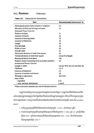
tarag 10>1 eGaynUvkMritlMeGogEdlGacGnuvtþsMrab;tMN.
10.3. Ggát;smas Composite Members
dUcEdl)anerobrab;lMGitenAkñúgCMBUkTI5 BIEpñkEpñk5>7 eTAEpñk5>11/ eKRtUvFanakarepÞr
kMlaMgkat;tamTisedkenARtg;épÞb:HrvagGgát;cak;Rsab; nig situ-cast-topping. ]TahrN_ 5>14
bgðajBIkMlaMgGnþrGMeBI (interaction forces) nig flowchart énEpñk 5>8>2 eGay operational step-
by-step design procedure nigsmIkarKNnaEdlGacGnuvtþ)an (applicable design equation). rUbTI
5>18 én]TahrN_ 5>3 ehIykarsikSaKNnapþl;nUvTMhM nigKMlatrbs; dowel EdlmanT§iBldl;kar
epÞreBj eljénkMlaMgkat;tamTisedkrvagGgát;EdlP¢ab;Kña.
10.4. RTnab;TMrebtugGarem:enAkñúgGgát;smas
Reinforced Concrete Bearing in Composite Members
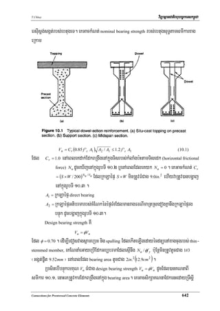
rUbTI 10>1 bgðajBI composite-action dowel reinforcement. edIm,IkarBarebtugEdlb:H
bearing edaypÞal;kuMeGaypÞúHEbkedaysarkMlaMgsgát;FelIslub eKRtUvGnuvtþkMlaMgxageRkAeTAelI
M
bearing EdlmanTMhMFMRKb;RKan;. kareFVIEbbenHkugRtaMgEdlTTYl)anBIsßanPaBkMNt;nwgminFMelIs
tMNsMrab;Ggát;ebtugeRbkugRtaMg 641](https://image.slidesharecdn.com/x-connectionsforprestressedconcreteelement-100716020536-phpapp02/85/X-connections-for-prestressed-concrete-element-3-320.jpg)
![T.Chhay viTüasßanCatiBhubec©keTskm<úCa
cMNaMfa eKRtUvf<k;EdkBRgwgTaMgGs;enAelIRCugNak¾edayrbs;bøg;sñameRbHsnμt;eGay)an
l¥eday development length b¤edaykarpSareTAnwgEdkEkg (angles)/ EdkbnÞH b¤EdkTMBk; (hooks)
edIm,IbegáItkMlaMgTb;Tl;Edl)anKNna.
KNnaRTnab;TMrebtugGarem:
10.4.1. Reinforced Bearing Design
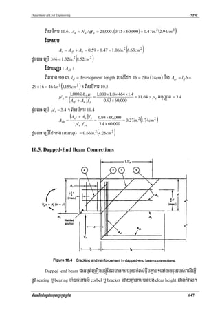
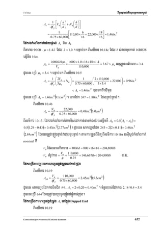
]TahrN_ 10>1³ FñwmebtugeRbkugRtaMgragctuekaN PCI standard 16RB28 rgkMlaMgkat;emKuNbBaÄr
Vu = 90,000lb(400kN ) nigkMlaMgTajtamTisedk N u = 21,000lb(93.4kN ) . FñwmRtUv)anRTenAelI
Teflon pad TMhM 4in. × 4in.(10cm × 10cm ) . KNna end reinforcement enAkñúgFñwmEdlGackarBarkar
ekItman bearing crack tamTisedk b¤tamTisQr. eKeGayTinñn½yxageRkam³
f 'c = 5,000 psi (34.47 MPa ) ebtugTMgn;Fmμta
f y = 60,000 psi sMrab;EdkFmμtaTaMgGs; (413.7 MPa )
θ = 20 o
dMeNaHRsay³
EdktamTisedk (Avf + An )
sMrab;karkMNt;EdkBRgwgtamTisedk/ sakl,gEdk #6
kMBs;Fñwm h = 28in. b = 16in.
BItarag 10>3/ ld = 29in.
Acr = l d b = 29 × 16 = 464in.2
BItarag 10>2/ μ = 1.4 nigBIsmIkar 10.3
1,000λAcr μ 1,000 × 1.0 × 464 × 1.4
μe =
Vup
=
90,000
= 10.61 > μ e GnuBaØat = 3.4
dUcenHeRbI μe = 3.4
BIsmIkar 10.2
Avf =
Vup
φf y μ e
=
90,000
0.75 × 60,000 × 3.4
(
= 0.59in.2 3.4cm 2 )
N u = 21,000lb
N u 21,000
=
Vu 90,000
= 0.23 > tMélGb,brma 0.20
dUcenH yk N u = 21,000lb .
Connections for Prestressed Concrete Elements 646](https://image.slidesharecdn.com/x-connectionsforprestressedconcreteelement-100716020536-phpapp02/85/X-connections-for-prestressed-concrete-element-8-320.jpg)
![Department of Civil Engineering NPIC
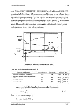
Vu
Vn = = Av f y + Ah f y + 2λbd f 'c (10.18)
φ
y:agehacNas;k¾eKRtUvdak;EdkBak;kNþalénEdkBRgwgenHbBaÄr dUcenHsmIkar 10.18 eGay
1 ⎛ Vu ⎞
Av, min = ⎜ − 2λbd f 'c ⎟
⎜φ ⎟ (10.19)
2 fy ⎝ ⎠
cMNaMfa karKitBIkareFVIkarTamTardUcxageRkam³
!> kMBs;rbs; dapped end y:agehack¾esμIBak;kNþalénkMBs;Fñwm elIkElgkMBs;FñwmFMCag
tMrUvkar.
@> RbsinebIkugRtaMgBt;begáagEdlKNnasMrab;kMBs;eBjelj (full depth) rbs;muxkat;eday
eRbIbnÞúkemKuN nig gross section propertied FMCag 6 f 'c Pøam²BIeRkay dap/ eKKYrdak;
EdkBRgwgbeNþaybEnßmenAkñúgFñwmedIm,IbegáItersIusþg;Bt;begáagtMrUvkar.
#> eKRtUvdak;EdkrgkarTajGgát;RTUg Ash eGaykan;EtEk,rkac;RCug. EdkBRgwgenHCaEdk
bEnßmeTAelIEdkrgkMlaMgkat;KNna (design shear reinforcement) EdlRtUvkarsMrab;mux
kat;FñwmEdlmankMBs;eBj.
10.5.2. KNnatMNrbs; Dapped end Beam
Dapped-End Beam Connection Design
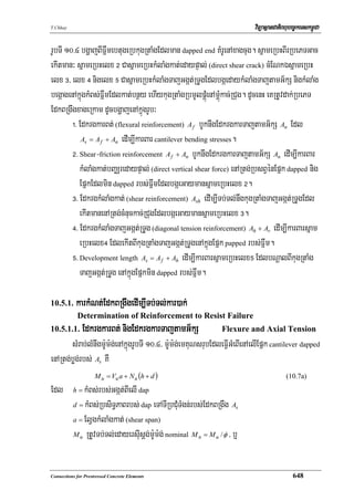
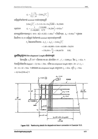
]TahrN_ 10>2³ FñwmebtugeRbkugRtaMg PCI standard 16RB28 Edl dapped enAxagcugsMrab;
bearing enAelI column corbel/ rgnUvkMlaMgkat;TMnajemKuNenAxagcug Vu = 110,000lb(489kN )
nigkMlaMgTajtamG½kStamTisedk Nu = 20,000lb(97.9kN ) . KNnaEdkrgkarBt;begáag Edkrg
kMlaMgkat;edaypÞal; nigEdkrgkarTajGgát;RTUg As / Ash / Ah nig Av EdlRtUvkarsMrab;karBarsñam
eRbH EdlbNþalBI dapping énFñwmxagcug. Tinñn½yEdleKeGayman f 'c = 5,000 psi(34.5MPa)
ebtugTMgn;Rsal ehIy f y = 60,000 psi(414Mpa) .
dMeNaHRsay³
snμt;fa shear span a = 6in.(152mm) / kMBs;RbsiT§PaB dapped-end d = 16in.(406mm)
nig h = 18in.(457mm) .
EdkrgkarBt; nigEdkrgkarTajtamG½kS As
Nu 20,000
= = 0.18 < 0.20
Vu 110,000
dUcenH N u = 0.20 ×110,000 = 22,000lb(97.9kN )
tMNsMrab;Ggát;ebtugeRbkugRtaMg 651](https://image.slidesharecdn.com/x-connectionsforprestressedconcreteelement-100716020536-phpapp02/85/X-connections-for-prestressed-concrete-element-13-320.jpg)
![T.Chhay viTüasßanCatiBhubec©keTskm<úCa
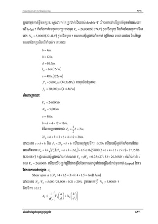
EdkBRgwg Ah KWEdkGkSr U #4 . dUcenHBItarag 10>3/ 1.7ld = 32in.(81cm) BIeRkayFñwm
dap. rUbTI 10>5 bgðajBIkarlMGitEdksMrab;tMNFñwm dapped.
10.6. Brackets nig Corbel ebtugGarem:
Reinforced Concrete Brackets and Corbels
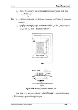
Corbel CaFñwm cantilever xøI EdlpleFob shear span elIkMBs; a / d minRtUvFMCag 1.0 . varg
kMlaMgkat;edaypÞal; Vu nigkMlaMgTajtamTisedk N u . Epñk 5.14 enAkñúgCMBUk5/ design flowchart
enAkñúgEpñk 5.14.4 nig]TahrN_ 5>7 bgðajBIkMlaMgsgát; nigkarGnuvtþénRTwsþI shear-friction enAkñúg
karsikSaKNna corbel. karlMGitsrésEdkrbs;tMNCakargard¾sMxan;mYyedIm,ITTYleCaKC½ykñúgkar
sikSaKNna corbel edayKitBIlT§PaBrbs;vaedIm,ITb;Tl;nwgGnuvtþkMlaMgGnuvtþn_. srésEdklMGit
rbs; corbel KMrURtUv)anbgðajenAkñúgrUbTI 10>6.
Connections for Prestressed Concrete Elements 654](https://image.slidesharecdn.com/x-connectionsforprestressedconcreteelement-100716020536-phpapp02/85/X-connections-for-prestressed-concrete-element-16-320.jpg)
![Department of Civil Engineering NPIC
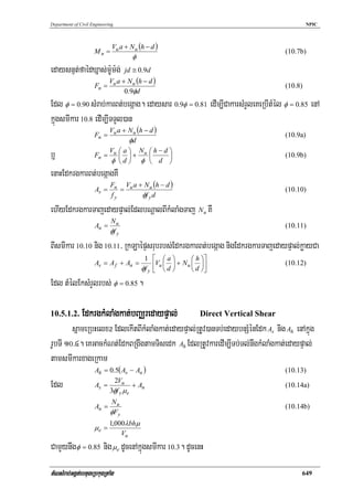
10.7. Epñklyecjrbs;FñwmebtugGarem:
Concrete Beam Ledges
eKeRbI beam ledge edIm,IRTbnÞúkcMcMnuccugFñwmebtugeRbkugRtaMgcak;Rsab;tamTisTTwg ehIyva
eFVIkarkñúgTMrg;RsedogKñanwg corbel Edr. kM;laMgedaypÞal;EdleFVIGMeBIelI ledge GacbgáeGaymansñam
bBaÄrdUcbgðajenAkñúgrUbTI 10>7. RbsinebIbnÞúkCabnÞúkminCab; ehIymkBIRCugmçag/ ledge beam kñúg
TMrg;GkSr L eFVIGMeBIdUc spandrel beam nigrgm:Um:g;rmYlbEnßmBIelIkMlaMgkat;edaypÞal;. karKNna
ledge beam KWGnuvtþtamkarsikSaKNna nig]TahrN_enAkñúgCMBUk5. enAkñúgemeronenHbgðajBIkar
sikSaKNnaEdkrgkMlaMgkat;sMrab; cantilevering ledge EdlCaTUeTAmanpleFob shear span elI
kMBs; l p / d tUcCag b¤esμInwg 0.5 .
eKRtUvkMNt;esIusþg;kMlaMgkat; nominal rbs; ledge Rtg;kac;RCugedaytMéltUcCageKkñúg
cMeNamtMélEdlTTYlBIsmIkar nigeRkamlkçxNÐEdleKeGaydUcxageRkam
!> s > b + h
tMNsMrab;Ggát;ebtugeRbkugRtaMg 655](https://image.slidesharecdn.com/x-connectionsforprestressedconcreteelement-100716020536-phpapp02/85/X-connections-for-prestressed-concrete-element-17-320.jpg)
![T.Chhay viTüasßanCatiBhubec©keTskm<úCa
(
Vn = 3hλ f 'c 2l p + b + h ) (10.20a)
(
Vn = hλ f 'c 2l p + b + h + 2d e ) (10.20b)
@> s < b + h nigbnÞúkcMcMnucesμIKña
(
Vn = 1.5hλ f 'c 2l p + b + h + s ) (10.21a)
⎛ b+h ⎞
Vn = hλ f 'c ⎜ l p + + de + s ⎟ (10.21b)
⎝ 2 ⎠
Edl RbEvglyecjrbs; ledge
lp =
b = TTwgrbs; bearing area
h = kMBs;rbs; ledge
s = KMlaténbnÞúkcMcMnuc
d e = cMgayBIG½kSénbnÞúkeTAcugFñwm
RbsinebI ledge RTbnÞúkCab; b¤bnÞúkcMcMnucEdlmanKMlatEk,rKña eKkMNt;ersIusþg;kMlaMgkat;
nominal rbs;muxkat; ledge BI
Vn = 24hλ f 'c (10.22)
Edl Vn CakMlaMgkat;kñúgmYyÉktþaRbEvg. y:agehacNas; eKRtUveGayersIusþg;KNna Vu esμInwgkM
laMgemKuN Vu = φVn sMrab; φ = 0.85 . RbsinebIbnÞúkemKuNGnuvtþn_ Vu FMCagersIusþg;KNna dUc
EdlkMNt;BIsmIkar 10.20, 10.21 b¤ 10.22/ eKRtUvdak;EdkBiessEdlKNnaRsedogKñaeTAnwgEdk
EdlRtUvkarenAkñúgcug dapped beam dUcEdl)anerobrab;enAkñúgEpñk 10.5. enAkñúgkrNIenH eKRtUv
kMNt;EdkrgkarBt; As BIsmIkar 10.12/ EdkBRgwgrgkarTajGgát;RTUgbBaÄr (hanger) Ash BI
smIkar 10.17 ehIyEdkBRgwgbEnßm At Edldak;enAsrésxagelI nigsrésxageRkamrbs; ledge BI
200l p d
At = (10.23)
fy
Edl At CaRkLaépÞrbs;EdkbeNþayenAkñúg ledge. eKdak;EdkBRgwg Ash edayKMlatesμIKñaelITTwg
6h énRCugnImYy²rbs; bearing b:uEnþminRtUvFMCagBak;kNþalcMgayeTAkan;bnÞúkbnÞab;. KMlatEdkmin
RtUvFMCagkMBs; ledge h b¤ 18in. ehIy Ash RtUv)ansikSaKNnasMrab; ledge EdlminRtUvbEnßmeTAelI
EdkrgkMlaMgkat; nigEdkrgkMlaMgrmYlrbs; ledge beam srub.
karKNnatMNFñwmlyecj
10.7.1. Design of Ledge Beam Connection
]TahrN_ 10>3³ eRKOgbgÁúMkMralGaKarcMNtrfynþRtUv)anpSMeLIgBI 10 ft -wide double-T RtUv)an
Connections for Prestressed Concrete Elements 656](https://image.slidesharecdn.com/x-connectionsforprestressedconcreteelement-100716020536-phpapp02/85/X-connections-for-prestressed-concrete-element-18-320.jpg)
![T.Chhay viTüasßanCatiBhubec©keTskm<úCa
=
1 ⎡ 6 12 ⎤
( )
⎢24,000 10.5 + 5,000 10.5 ⎥ = 0.38in. 2.45cm
0.85 × 60,000 ⎣ ⎦
2 2
edaysar 6h = 6 ×12 > s / 2 = 24in. / EbgEckEdkBRgwg s / 2 = 24in. enARCugnImYy²énbnÞúk.
TTwgrbs; band sMrab;kardak;EdkrgkarBt;begáag A = 2 × 24 = 48in. ehIyKMlatEdkGti-
s
brma h = 12in. . dUcenHeRbIEdk 4#3 enAkñúg band width 48in. nImYy² = 0.44in. > EdktMrUvkar
2
0.38in. . dUcenH dak;EdkbEnßmBIrenARtg;cugFñwmedIm,Ipþl;EdksmmUlsMrab;eCIgFñwmEdldak;Ek,r
2
xagcug.
EdkbBaÄrrgkarTajGgát;RTUg A sh
BIsmIkar 10.17
= 0.53in. (3.42cm )
V 24,000
A = = u 2 2
φf
sh
0.75 × 60,000
y
elI hand width 48in. . dUcenH Ash / ft = 0.47 / 4 = 0.12in.2 / ft b¤ #3@11in. . Cavi)akeRbIEdkkg
biTCit 5#3 enAkñúg bad width 48in. = 0.55in.2 > muxkat;EdktMrUvkar 0.53in.2 . bnÞab;mk sMrab;kargar
Gnuvtþn_ eRbIcMnYn nigKMlatdUcKñasMrab;Edk As nig Ash ¬EdkkgbiTCit 5#3 ¦. cMNaMfa manEteCIgmçag
rbs;Edkkg Ash RtUv)anKitbBa©ÚleTAkñúgmuxkat;én 5#3 edIm,Ipþl;karRbmUlpþúMtMrUvkarénEdkEk,rkac;
RCug.
EdkbeNþay Al
BIsmIkar 10.23
200l p d 200 × 6 ×10.5
Al = = = 0.21in.2
fy 60,000
sMrab;kargarGnuvtþn_ eRbIEdk #4 mYyenARtg;kac;RCugrbs; ledge edayeGay 4#4 = 0.80in.2 ¬Ggát;
p©it 12.7mm ¦ > 0.21in.2 / O.K.
CakarBit karKNnaEdlmanlkçN³eBjeljTamTarkarviPaKkMlaMgkat; nigkMlaMgrmYlrbs;
muxkat;srubedIm,ITb;Tl;nwgkMlaMgkat;srubEdlbBa¢ÚnedayeCIgrbs; double-T TaMgGs; nigm:Um:g;rmYl
EdlekIteLIgedaykarGnuvtþrbs;kMlaMgcakp©itBIeCIgrbs; double-T. karerobrab;BIRkLaépÞEdkBRgwg
rbs; ledge Edl)anKNnaenAkñúg]TahrN_enHCaRkLaépÞEdkbEnßmeTAelIelIEdkrgkMlaMgTaj nig
Edkrg kMlaMgrmYlEdlTamTarsMrab;Fñwmsrub.
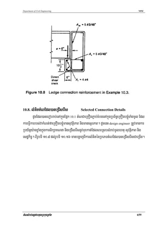
rUbTI 10>8 bgðajBIkarlMGitrbs;srésEdksMrab;tMN ledge, b:uEnþmin)anrab;bBa©ÚlEdkrgkM-
laMgTaj nigEdkrgkMlaMgrmYlEdlRtUvsikSasMrab;FñwmGkS L TaMgmUl.
Connections for Prestressed Concrete Elements 658](https://image.slidesharecdn.com/x-connectionsforprestressedconcreteelement-100716020536-phpapp02/85/X-connections-for-prestressed-concrete-element-20-320.jpg)
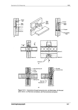
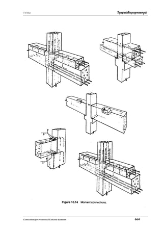
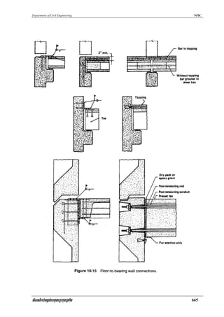
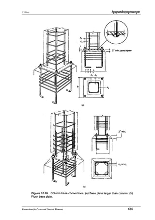

This document provides guidance on connections for prestressed concrete elements. It discusses tolerance requirements for connections, introduces composite members formed using situ-cast topping, and describes reinforced concrete bearing in composite members. Specifically, it outlines procedures for calculating the design bearing strength of a reinforced concrete bearing using nominal strength equations. It also presents equations for determining the development length and shear capacity of reinforcing bars at the interface between a concrete bearing and a composite member. The guidance aims to ensure connections have adequate strength and durability while also considering constructability and economics.


