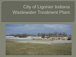
The document summarizes the history and upgrades of the City of Ligonier WWTP located at 305 Bridge Street. Key points include:
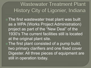
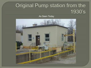
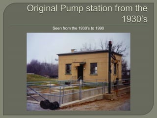
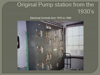
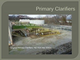
- The original plant from the 1930s consisted of a pump building, two primary clarifiers, and one fixed cover digester.
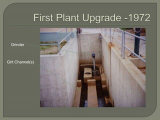
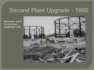
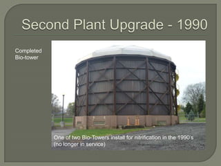
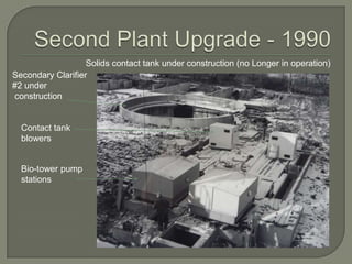
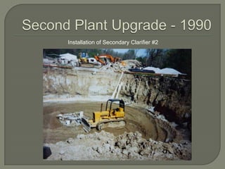
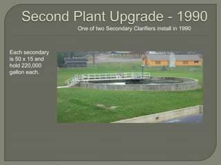
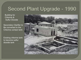
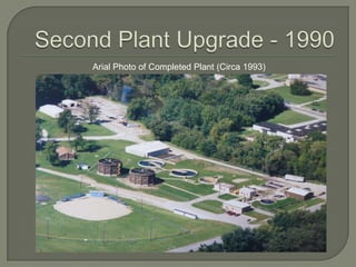
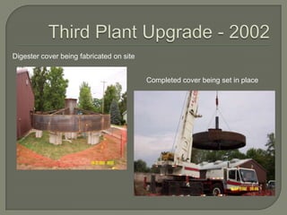
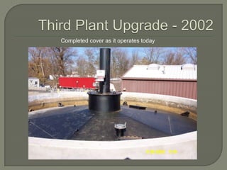
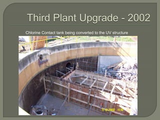
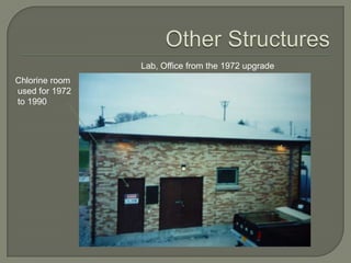
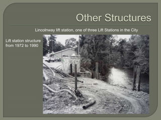
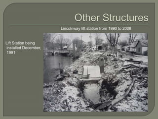
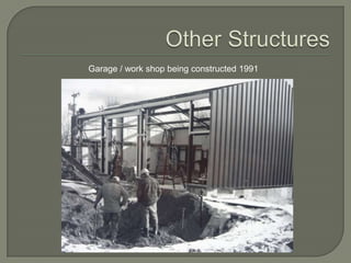
- Major upgrades occurred in 1972, 1990, 2002, and 2008. These included expanding capacity to 1.5 MGD, adding primary clarifiers, biological treatment, and converting to an activated sludge process.
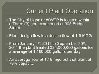
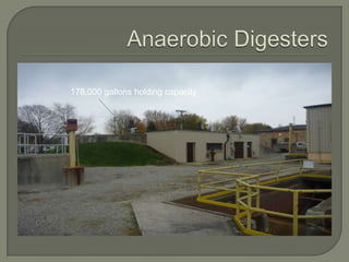
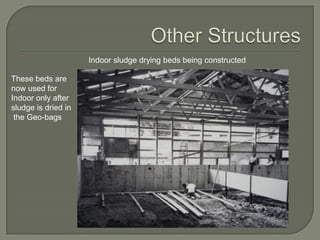
- Current treatment involves anaerobic digestion with two floating cover digesters, sludge dewatering using geobags, and UV disinfection. The plant operates at 78% of its design capacity of 1.


![5G Explained! A High Level Overview [Introduction]](https://cdn.slidesharecdn.com/ss_thumbnails/5gexplainedahighleveloverview-260119165306-cc137a3e-thumbnail.jpg?width=640&height=640&fit=bounds)


