SlideShare a Scribd company logo
1 of 7
Download to read offline
NOTES ON VISIT TO BIOGAS PLANT AT PADARTHA AT FOOD PARK
(As documented by S.Ananthanarayana Sharma, Ranjit Gupta Centre for
Documentation of Action Research, and further corrected by Mr. Saurabh
Mishra, Process Engineer, Biogas Plant, Patanjali BioResearch
Institute, Padartha Food Park, Hardwar and submitted to Dr.G.Paran
Gowda, Board member PBRI)
Time: 31
st
January 2013. From 12.50 to 14.30 hours
(Anant had spent a couple of days understanding the equipment flows,
earlier to this discussion).
People: -
Mr. Saurabh Misra, Process Engineer, PBRI
Mr. Aman Kumar, Manager (Operations) PBRI
Mr.Sanjay Rachelli, Officer - Projects,of Kirloskar Integrated
Technologies Limited (KITL) for a very brief discussion
CONTEXT TO THE VISIT:
S.Ananthanarayana Sharma,(Anant hereafter) Aman Kumar (Aman hereafter)
and Saurabh Mishra (Saurabh hereafter) had been involved in collating
the documents for the No Objection Certificate (NOC) from the
Uttarakhand Pollution Prevention and Control Board. This visit, was in
the nature of an orientation one - to get to understand the
technologies behind the newly erected 6000 cubic metre plant. Also
Anant had worked with smaller plants,(60 cubic metres)- as a part of
the biogas program with the milk cooperative AMUL in 1985-87. The
visit was to update his knowledge and pass on some of his insights to
Aman and Saurabh.
PLANT OPERATIONAL PLANNING:
KITL had planned the plant initially around some projects of organic
waste that would be generated as a result of the various food
processing industries of Patanjali Food and Herbal Park. However the
actual production and the consequent organic waste generated had not
been as per projections. The current thinking appears to be to shift
to purchased cow dung as feedstock - to make up for the deficit in
availability of raw material from the food park manufacturing units.
As per the NOC submitted, around 120MT was the planned input organic
waste. Presently around 20MT of organic waste can be expected from
Padartha food park operations. The present planning is to purchase
some 100 MT of cow dung per day for the plant operations.
The original plan envisaged production of around 0.6 to 1 MW of power,
from the scrubbed methane. However, the present operational planning:
is to delay commissioning of the electric power generation unit. The
scrubbed methane is to be fed by a pipe to the boiler unit, a few
hundred metres from the plant: as fuel for boiling water to convert to
steam for plant operations in the Food Park.
The planning for biofertiliser, did not appear to be completely
thought through in the original planning. There were some vague
references to adding rock phosphate to dried slurry to make
biofertiliser. The Patanjali Bio Research Institute (PBRI) has
successfully demonstrated a business model around sale of
biofertilisers. These live experiences are in the process of being
incorporated in the manufacturing design process - in terms of a plant
to reduce moisture from the slurry, and then transferring the contents
to open air lagoons, for drying - before mixing and packing.
The observations are presented, in terms of the movement of the
material, from the input cow dung and organic waste - to the output
methane and slurry for biofertiliser manufacturing.
Various photographs taken, are attached in a separate document which
can be cross referred to for clarification.
INLET TANK
There is a tin shed, with a large pit - which has an approximately 5
MT capacity mild steel .inlet tank: with a pipe and pump connected to
the mixing tank. The following action points can perhaps be discussed.
1. Is there a necessity for specifying dimensions for the organic
waste /biomass that is used to be feedstock? Example -
Saurabh’s statement that Aloe Vera waste should be pulverised
to less then 1mm size and Amla (Phyllanthus emblica - Indian
Gooseberry) should be chopped.This is necessary for proper
digestion in digester and smooth movement of slurry by pumps
installed.
2. If there is a scientific/technical merit in these statements,
is there a need for a “pre treatment shed”- with necessary
pulverising, chopping, and crushing equipment? The shed would
also be required for temporary storage and protection during
rains..
3. There are visible rust spots on the tin shed roof. KITL has
been apparently asked by Saurabh to paint the shed before
formally handing over the pant.
PIPING AND PUMP FROM INLET TANK MIXING TANK
The piping and the pump has been installed. All the pumps for shifting
the raw material from the inlet tank to mixing tank have been
completed as per Saurabh. The following action points can be
discussed?.
1) Water line has been s installed for moisturizing the feed in
inlet tank.Are there some technical norms of moisture content -
to facilitate easy flow of material from the inlet tank to mixing
tank?
2) As per Saraubh “flow parameters” are dependent on total solids
present in feed. During the commissioning period, the technical
specifications-like How much flow per hour? At what
concentration (in terms of moisture content)? should be
standardised.
MIXING TANK
Mixing tank is to be commissioned The water pipes for hot water has
been painted in black, to enable absorption of heat. There is a
submersible pump, which is installed near the water treatment plant
(which is a few hundred metres away) which is successfully pumping
water into the mixing tank. Some action points for discussion?
1) Technical specifications of mixing tank capacity, water
required? Biodigester will work on 5 to 6% T.S.We need to mix
water according to feed, accordingly.
2) Any provision of backup for water pumping, in case the existing
pump fails, in between mixing operations? There are two
submersible pumps. The necessity for another backup submersible
pump can be perhaps taken up after plant commissioning, depending
on the performance of the existing pump.
BUFFER TANK
The buffer tank is holding some cow dung and water mixture. There
seems to exist some technical norms, as per Saurabh, as under -
• pH value - 7.0
• Temperature - 35 to 42 degrees Celsius
• Dilution - Total Solids -6-8%
Some specific action points for discussion.
1) No written technical specifications/operations manual on mixing
tank capacity, operations, safeguards, etc. Saurabh stated that
KITL will give all the manuals during handing over of plant after
successful commissioning-which needs to be ensured.
2) There does not seem to exist any diagrams for piping, wiring,
etc. Saruabh states that KITL will give all the diagrams of
piping during handing over of plant after successful
commissioning- which needs to be ensured..
LABORATORY
A laboratory needs to be equipped to test the material, at various
process points, for pH value, temperature, Total Solids %age, BOD,
COD, etc. An action point for discussion?
1) The list of equipment, methods of testing, methods of drawing
samples, protocols for information sharing, etc Saurabh states
that KITL will give all the details.- which needs to be received
in some sort of time frame- to enable preparation of SOPs for
sampling, and analytical measurements.
PIPING FROM BUFFER TANK TO DIGESTER
Piping seems to have been commissioned to pump the initial cowdung
mixture to the digester.
DIGESTER
The digester is stated to have a capacity of 6000 cubic metres. There
are many pipes going in and out of the digester, as also around the
digester.
On top of the digester:
A number of pipes have been projected from the digester’s head. This
includes a yellow painted, large (8 inch diameter) pipe, which is
stated to be a sort of a flare? Another 6 inch diameter pipe, painted
white is stated to be a vent?
A water tank (with around 2000 litres capacity) has been mounted. This
tank is designed for cooling the stirring motors, as per Saurabh.
There seems to be some pipes which according to Saurabh, are supposed
to flow gas to some gas pressure gauge (manometer)
A large motor has been mounted exactly on top of the digester, which
is stated to be the machine for stirring the mixture within the
digester.
Another blue painted valve has been mounted. Saurabh stated that this
was a “Breather valve”, , which purpose is for safety.
A metal frame has also been erected, which function is stated to be
that of a lightening arrestor.
There is a complicated maze of piping, leading from the digester to
the degasifier and to the floating dome holder. Some pipes seem to be
for recycling material?
Bottom of digester
There are eight pipes, coming out of the digester at different
heights. These have been stated by Saurabh to be “sampling ports” for
taking samples of the digested slurry within the digester?
There is some gauge which is stated to be a pressure metre?
There exists some colour coding of pipes - in yellow, green, red, etc.
Output of digester
Usually biogas digesters have two main output - METHANE and SLURRY.
It appears that a large yellow painted pipe leading to the gas holder,
is for transporting methane gas?
Slurry seems to be led out by some black painted pipe? There is also
some complex piping from the digester to the degasser? This could
probably be slurry, which will overflow to the degasser, and then led
back after recycling?
Some action points for discussion with KITL during handing over..
1) Piping diagram, alongwith block/process flow diagram exclusively
for the digester.
2) Instrumentation in the digester.
3) An engineering diagram, with another specific cross section
diagram.: clearly specifying dimensions, and indicating the name
of the various parts/components installed.
4) Standard Operating Procedures and Operating manual for digester.
This should include simple diagrams with photographs, explaining
the various gauges, pipes, and pumps installed on the digester
walls and top.
DEGASSER
There is a tall hollow tubular column, installed next to the digester.
This was stated to be the degasser. This could be also some sort of a
decision point - for segregating slurry - back to the digester for
processing, and to the biofertiliser unit. There appeared to be a
green pipe, for connecting the digester and the degasser and red pipe,
for connecting the biofertiliser unit with the degasser?
It appears that the red pipe is the sole source of supply to the
biofertiliser unit (called separation unit?).(Known as decanter )
The list of pipes leading out of the degasser seems to be as under-
1) Four outlet pipes to mixing tank (?)
2) Big green pipe to digester
3) Big green pipes let to floor, presumably to effluent treatment?
4) Red pipe to to decanter for liquid solid separation. unit (for
biofertiliser?)
The degasser seems to be some new technology not commonly used in the
smaller biogas plants that are routinely installed. Hence some action
points for discussion with KITL at time of commissioning..
1) A short technical note, explaining clearly what is the “technical
value addition” of this degasser. And what is the technology, and
how does this work? Saurabh states that the primary function is
for managing overflow of digester.
2) An engineering diagram, with another specific cross section
diagram.: clearly specifying dimensions, and indicating the name
of the various parts/components installed.
3) Piping diagram, and instrumentation diagram exclusively for the
degasser. .
4) Standard Operating Procedures and Operating manual for the
degasser. This should include simple diagrams with photographs,
explaining the various pipes, going in and out of the degasser.
METHANE GAS HOLDER
There are two gas holders. This paragraph is on the first gas holder,
from the digester.
A big (8 inch diameter) yellow pipe leading from the digester to the
gas holder, seems to be the sole source of input- which could be
methane gas? There seems to be some white painted Mild Steel tank -
which Saurabh stated was for removing moisture from gas before the
pipe enters the holder. There is a black V shaped pipe, outside the
gas holder, which too according to Saurabh could be for removing
excess water from gas holder. Some action points for discussion with
KITL.
1) Saurabh stated that the biogas holder will hold the raw methane
gas produced from fermentation process and supply the gas to the
scrubber with constant pressure. Air blower regulates the
variation between gas input and output, thus keeping the gas
pressure inside the biogas holder at a constant level. An
engineering diagram, with another specific cross section
diagram.: clearly specifying dimensions, and indicating the name
of the various parts/components installed.
2) Piping diagram, and instrumentation diagram exclusively for the
degasser. .
3) Standard Operating Procedures and Operating manual explaining the
various pipes, going in and out of the gas holder.
BLOWERS
Two large pumps have been installed next to the first gas holder. This
could be probably for pumping methane gas to scrubber.
Some action points for discussion with KITL.
1) A short technical note, specifying the precise nature of, the
regulation of the variation between gas input and output: to
keep the gas pressure inside the biogas holder at a constant
level Some numbers regarding the optimal pressure, method of
measurement, regulation of blower speed?
2) An engineering diagram, with another specific cross section
diagram.: clearly specifying dimensions, and indicating the name
of the various parts/components installed.
3) Piping diagram, and instrumentation diagram exclusively for the
blowers .
4) Standard Operating Procedures and Operating manual explaining the
various pipes, going in and out of the gas holder.
SCRUBBER
The scrubber is stated to be a “patented technology” developed by
KITL. The scrubber is a tall (10 metres) tubular column, with a base
of around 32 inches diameter. It appears to be made of fibre glass.
Two large 6 inch diameter yellow painted pipes: presumably are for
piping methane gas. There is a 3 inch diameter HDPE pipe with a valve.
There are two pumps. Saurabh said that “elemental sulphur” was to be
removed through this scrubber.
There is water tank, presumably for storing water from the Reverse
Osmosis (RO) plant. Apparently the planning for the food park to
provide RO water of around 5 cubic metres per day. The piping from
the RO plant to the scrubber has to laid by PBRI.
Some action points for discussion with KITL
1) The purpose of the scrubber, as per Saurabh appears to be for
removing the H2s which can corrode the engine if not separated.
Some numbers regarding the expected range of moisture content in
the input gas, the technical value addition, in terms of
moisture removal, and the output moisture level in the methane
gas could be forecasted? And later tested during commissioning?
2) An engineering diagram, with another specific cross section
diagram: clearly specifying dimensions, and indicating the name
of the various parts/components installed.
3) Piping diagram, and instrumentation diagram exclusively for the
scrubber .
4) Standard Operating Procedures and Operating manual explaining the
various pipes, going in and out of the scrubber.
5) If possible, the patent document filed (which is a public domain
document) can be obtained to get some more details?
OTHER UNITS
There is a second methane gas holder, presumably to store
desulphurised methane from the scrubber. The scrubbed methane will
presumably sent by a newly laid pipe, to the boiler unit, which is
around 300 hundred metres away.
The electricity generation unit has some of the machinery installed.
Apparently this is not going to be commissioned with the digester.
Some action points for discussion with KITL.
1) After production of gas and testing of all systems, the
specifications of the methane gas that is to be sent to the
boiler, should be clearly stated.
2) A note explaining how the electric generation plant works in
theory. Which can be used later for experimentation by reknowned
scientists like Dr.G.Paran Gowda or IIT (Roorkee/Delhi)
professors
POSSIBLE BLOCK DIAGRAM FOR BIOGAS PLANT AS PER LIMITED UNDERSTANDING OF S.ANANTHANARAYANA SHARMA
BASED ON THE OBVERSATIONS ON 31 JANUARY 2013
Inlet tank
Mixing
tank
Buffer
tank
BIOGAS DIGESTER
DEGASSER
SEPARATION
UNIT FOR
BIOFERTILISER
METHANE
GAS Holder
Blowers
SCRUBBER
Scrubbed
Methane to
boiler

More Related Content

What's hot

Packaged Sewage Treatment Plant
Packaged Sewage Treatment PlantPackaged Sewage Treatment Plant
Packaged Sewage Treatment PlantSuresh Kumar
 
Kelani River Water Treatment Plant in Colombo
Kelani River Water Treatment Plant in ColomboKelani River Water Treatment Plant in Colombo
Kelani River Water Treatment Plant in ColomboAnton Ricalovskis
 
Ligonier Wastewater Treatment Plant Presentation
Ligonier Wastewater Treatment Plant PresentationLigonier Wastewater Treatment Plant Presentation
Ligonier Wastewater Treatment Plant Presentationfought70
 
Planning & Operating Electricty Network with Renewable Generation-4
Planning & Operating Electricty Network with Renewable Generation-4Planning & Operating Electricty Network with Renewable Generation-4
Planning & Operating Electricty Network with Renewable Generation-4Power System Operation
 
BOD Source Reduction For Beverage Plants 2010
BOD Source Reduction For Beverage Plants 2010BOD Source Reduction For Beverage Plants 2010
BOD Source Reduction For Beverage Plants 2010RecoverySystems
 
Presentation On Sustainability April 2009 Final
Presentation On Sustainability April 2009 FinalPresentation On Sustainability April 2009 Final
Presentation On Sustainability April 2009 FinalAndy Rayner
 
51f10add07c59 cleaning in_place_systems_design_manual
51f10add07c59 cleaning in_place_systems_design_manual51f10add07c59 cleaning in_place_systems_design_manual
51f10add07c59 cleaning in_place_systems_design_manualKyriakos Michalaki
 
final with references
final with referencesfinal with references
final with referencesAnil Vibhute
 
Converde colombia
Converde   colombiaConverde   colombia
Converde colombiaconverde
 
UNCONVENTIONAL GAS- DRILLING FOOTPRINT REDUCTION CHALLENGE
UNCONVENTIONAL GAS- DRILLING FOOTPRINT REDUCTION CHALLENGE UNCONVENTIONAL GAS- DRILLING FOOTPRINT REDUCTION CHALLENGE
UNCONVENTIONAL GAS- DRILLING FOOTPRINT REDUCTION CHALLENGE Akhil Prabhakar
 
Waste to energy managenment
Waste to energy managenmentWaste to energy managenment
Waste to energy managenmentAbhijit Biswas
 
Construction of a Family sized Biodigester
Construction of a Family sized BiodigesterConstruction of a Family sized Biodigester
Construction of a Family sized Biodigester Titilope Fadipe
 
How DEWATS can be implemented to bio-remediate lakes
How DEWATS can be implemented to bio-remediate lakesHow DEWATS can be implemented to bio-remediate lakes
How DEWATS can be implemented to bio-remediate lakesbiomeshubha
 
WASTE WATER TREATMENT REFINERIES
WASTE WATER TREATMENT REFINERIES WASTE WATER TREATMENT REFINERIES
WASTE WATER TREATMENT REFINERIES Arun Sarasan
 
Converde colombia
Converde   colombiaConverde   colombia
Converde colombiaconverde
 
Zero Liquid Discharge Technology - UPL
Zero Liquid Discharge Technology - UPLZero Liquid Discharge Technology - UPL
Zero Liquid Discharge Technology - UPLprachishinde01
 

What's hot (20)

Packaged Sewage Treatment Plant
Packaged Sewage Treatment PlantPackaged Sewage Treatment Plant
Packaged Sewage Treatment Plant
 
Kelani River Water Treatment Plant in Colombo
Kelani River Water Treatment Plant in ColomboKelani River Water Treatment Plant in Colombo
Kelani River Water Treatment Plant in Colombo
 
Ligonier Wastewater Treatment Plant Presentation
Ligonier Wastewater Treatment Plant PresentationLigonier Wastewater Treatment Plant Presentation
Ligonier Wastewater Treatment Plant Presentation
 
Planning & Operating Electricty Network with Renewable Generation-4
Planning & Operating Electricty Network with Renewable Generation-4Planning & Operating Electricty Network with Renewable Generation-4
Planning & Operating Electricty Network with Renewable Generation-4
 
BOD Source Reduction For Beverage Plants 2010
BOD Source Reduction For Beverage Plants 2010BOD Source Reduction For Beverage Plants 2010
BOD Source Reduction For Beverage Plants 2010
 
Zero Liquid Discharge Plant
Zero Liquid Discharge Plant Zero Liquid Discharge Plant
Zero Liquid Discharge Plant
 
Presentation On Sustainability April 2009 Final
Presentation On Sustainability April 2009 FinalPresentation On Sustainability April 2009 Final
Presentation On Sustainability April 2009 Final
 
Pavan resume-09.02.16)
Pavan resume-09.02.16)Pavan resume-09.02.16)
Pavan resume-09.02.16)
 
51f10add07c59 cleaning in_place_systems_design_manual
51f10add07c59 cleaning in_place_systems_design_manual51f10add07c59 cleaning in_place_systems_design_manual
51f10add07c59 cleaning in_place_systems_design_manual
 
final with references
final with referencesfinal with references
final with references
 
Converde colombia
Converde   colombiaConverde   colombia
Converde colombia
 
UNCONVENTIONAL GAS- DRILLING FOOTPRINT REDUCTION CHALLENGE
UNCONVENTIONAL GAS- DRILLING FOOTPRINT REDUCTION CHALLENGE UNCONVENTIONAL GAS- DRILLING FOOTPRINT REDUCTION CHALLENGE
UNCONVENTIONAL GAS- DRILLING FOOTPRINT REDUCTION CHALLENGE
 
PPT OF OM
PPT OF OMPPT OF OM
PPT OF OM
 
Waste to energy managenment
Waste to energy managenmentWaste to energy managenment
Waste to energy managenment
 
Construction of a Family sized Biodigester
Construction of a Family sized BiodigesterConstruction of a Family sized Biodigester
Construction of a Family sized Biodigester
 
How DEWATS can be implemented to bio-remediate lakes
How DEWATS can be implemented to bio-remediate lakesHow DEWATS can be implemented to bio-remediate lakes
How DEWATS can be implemented to bio-remediate lakes
 
Tank Cleaning with BioSolve
Tank Cleaning with BioSolveTank Cleaning with BioSolve
Tank Cleaning with BioSolve
 
WASTE WATER TREATMENT REFINERIES
WASTE WATER TREATMENT REFINERIES WASTE WATER TREATMENT REFINERIES
WASTE WATER TREATMENT REFINERIES
 
Converde colombia
Converde   colombiaConverde   colombia
Converde colombia
 
Zero Liquid Discharge Technology - UPL
Zero Liquid Discharge Technology - UPLZero Liquid Discharge Technology - UPL
Zero Liquid Discharge Technology - UPL
 

Similar to Biogas Plant visit Jan 31 2013 incorporating comments of S…

Case Study of Compressed Bio Gas Plant Installed at Hingoniya Gaushala, Jaipu...
Case Study of Compressed Bio Gas Plant Installed at Hingoniya Gaushala, Jaipu...Case Study of Compressed Bio Gas Plant Installed at Hingoniya Gaushala, Jaipu...
Case Study of Compressed Bio Gas Plant Installed at Hingoniya Gaushala, Jaipu...IRJET Journal
 
Sweet and sour experience of commissioning 1
Sweet and sour experience of commissioning 1Sweet and sour experience of commissioning 1
Sweet and sour experience of commissioning 1Prem Baboo
 
Innovate to Grow_ Final Report
Innovate to Grow_ Final ReportInnovate to Grow_ Final Report
Innovate to Grow_ Final ReportGriffith Brown
 
Industrial visit to BHEL, Ranipet
Industrial visit to BHEL, RanipetIndustrial visit to BHEL, Ranipet
Industrial visit to BHEL, RanipetPritishTayal
 
Ashu kumar ppt
Ashu kumar pptAshu kumar ppt
Ashu kumar pptAshu Kumar
 
Anaerobi digestion
Anaerobi digestionAnaerobi digestion
Anaerobi digestionjhapchandra
 
L 3 quality and quantity of industrial wastes
L 3 quality and quantity of industrial wastesL 3 quality and quantity of industrial wastes
L 3 quality and quantity of industrial wastesDr. shrikant jahagirdar
 
Plumbing Codes
Plumbing CodesPlumbing Codes
Plumbing CodesParkco
 
018 ss bio fst 2010
018 ss bio fst 2010018 ss bio fst 2010
018 ss bio fst 2010Alex Lee
 
018 ss bio fst 2010
018 ss bio fst 2010018 ss bio fst 2010
018 ss bio fst 2010Alex Lee
 
Anaerobic Treatment of Textile Wastewater using EGSB
Anaerobic Treatment of Textile Wastewater using EGSBAnaerobic Treatment of Textile Wastewater using EGSB
Anaerobic Treatment of Textile Wastewater using EGSBIJSRD
 
Planning for Emergency Mass-Depopulation of Swine
Planning for Emergency Mass-Depopulation of SwinePlanning for Emergency Mass-Depopulation of Swine
Planning for Emergency Mass-Depopulation of SwineNational Pork Board
 
Mark Rice - Planning for Emergency Mass-Depopulation of Swine in Response to ...
Mark Rice - Planning for Emergency Mass-Depopulation of Swine in Response to ...Mark Rice - Planning for Emergency Mass-Depopulation of Swine in Response to ...
Mark Rice - Planning for Emergency Mass-Depopulation of Swine in Response to ...John Blue
 
Packaged drinking water mineral water
Packaged drinking water mineral waterPackaged drinking water mineral water
Packaged drinking water mineral waterEKrantipvtltd
 
Performance Evaluation of Dairy Wastewater Treatment Plant
Performance Evaluation of Dairy Wastewater Treatment PlantPerformance Evaluation of Dairy Wastewater Treatment Plant
Performance Evaluation of Dairy Wastewater Treatment PlantIRJET Journal
 

Similar to Biogas Plant visit Jan 31 2013 incorporating comments of S… (20)

Case Study of Compressed Bio Gas Plant Installed at Hingoniya Gaushala, Jaipu...
Case Study of Compressed Bio Gas Plant Installed at Hingoniya Gaushala, Jaipu...Case Study of Compressed Bio Gas Plant Installed at Hingoniya Gaushala, Jaipu...
Case Study of Compressed Bio Gas Plant Installed at Hingoniya Gaushala, Jaipu...
 
Sweet and sour experience of commissioning 1
Sweet and sour experience of commissioning 1Sweet and sour experience of commissioning 1
Sweet and sour experience of commissioning 1
 
Final report cive 540 1
Final report cive 540 1Final report cive 540 1
Final report cive 540 1
 
Innovate to Grow_ Final Report
Innovate to Grow_ Final ReportInnovate to Grow_ Final Report
Innovate to Grow_ Final Report
 
Industrial visit to BHEL, Ranipet
Industrial visit to BHEL, RanipetIndustrial visit to BHEL, Ranipet
Industrial visit to BHEL, Ranipet
 
W2E- Div- PPT
W2E- Div- PPTW2E- Div- PPT
W2E- Div- PPT
 
L43056874
L43056874L43056874
L43056874
 
Ashu kumar ppt
Ashu kumar pptAshu kumar ppt
Ashu kumar ppt
 
Soil bio technology
Soil bio technologySoil bio technology
Soil bio technology
 
Anaerobi digestion
Anaerobi digestionAnaerobi digestion
Anaerobi digestion
 
L 3 quality and quantity of industrial wastes
L 3 quality and quantity of industrial wastesL 3 quality and quantity of industrial wastes
L 3 quality and quantity of industrial wastes
 
Plumbing Codes
Plumbing CodesPlumbing Codes
Plumbing Codes
 
Biogas technology
Biogas technologyBiogas technology
Biogas technology
 
018 ss bio fst 2010
018 ss bio fst 2010018 ss bio fst 2010
018 ss bio fst 2010
 
018 ss bio fst 2010
018 ss bio fst 2010018 ss bio fst 2010
018 ss bio fst 2010
 
Anaerobic Treatment of Textile Wastewater using EGSB
Anaerobic Treatment of Textile Wastewater using EGSBAnaerobic Treatment of Textile Wastewater using EGSB
Anaerobic Treatment of Textile Wastewater using EGSB
 
Planning for Emergency Mass-Depopulation of Swine
Planning for Emergency Mass-Depopulation of SwinePlanning for Emergency Mass-Depopulation of Swine
Planning for Emergency Mass-Depopulation of Swine
 
Mark Rice - Planning for Emergency Mass-Depopulation of Swine in Response to ...
Mark Rice - Planning for Emergency Mass-Depopulation of Swine in Response to ...Mark Rice - Planning for Emergency Mass-Depopulation of Swine in Response to ...
Mark Rice - Planning for Emergency Mass-Depopulation of Swine in Response to ...
 
Packaged drinking water mineral water
Packaged drinking water mineral waterPackaged drinking water mineral water
Packaged drinking water mineral water
 
Performance Evaluation of Dairy Wastewater Treatment Plant
Performance Evaluation of Dairy Wastewater Treatment PlantPerformance Evaluation of Dairy Wastewater Treatment Plant
Performance Evaluation of Dairy Wastewater Treatment Plant
 

More from S.Ananthanarayana Sharma

More from S.Ananthanarayana Sharma (12)

Plan and budget for aird ramnad 14 april 2014
Plan and budget for aird ramnad 14 april  2014Plan and budget for aird ramnad 14 april  2014
Plan and budget for aird ramnad 14 april 2014
 
PBRI Product flier 2013-14
PBRI Product flier 2013-14PBRI Product flier 2013-14
PBRI Product flier 2013-14
 
AKRUTI PBRI brochure 2013
AKRUTI PBRI brochure 2013AKRUTI PBRI brochure 2013
AKRUTI PBRI brochure 2013
 
IIT Roorkee workshop 31 March 2013
IIT Roorkee workshop 31 March 2013IIT Roorkee workshop 31 March 2013
IIT Roorkee workshop 31 March 2013
 
ICTBM Rudra + Anant 18-20 March2013
ICTBM Rudra + Anant 18-20 March2013ICTBM Rudra + Anant 18-20 March2013
ICTBM Rudra + Anant 18-20 March2013
 
iitm ssfrdt tsunami livelihood workshop proceedings
iitm ssfrdt tsunami livelihood workshop proceedingsiitm ssfrdt tsunami livelihood workshop proceedings
iitm ssfrdt tsunami livelihood workshop proceedings
 
Presentation to Uttarakhand Livestock Development Board Annual Meet Dehra Dun...
Presentation to Uttarakhand Livestock Development Board Annual Meet Dehra Dun...Presentation to Uttarakhand Livestock Development Board Annual Meet Dehra Dun...
Presentation to Uttarakhand Livestock Development Board Annual Meet Dehra Dun...
 
sharma_consultant_training IFGTB Aug 2010
sharma_consultant_training IFGTB Aug 2010sharma_consultant_training IFGTB Aug 2010
sharma_consultant_training IFGTB Aug 2010
 
Capacity Building Plan for World Bank _2 Jan03_
Capacity Building Plan for World Bank _2 Jan03_Capacity Building Plan for World Bank _2 Jan03_
Capacity Building Plan for World Bank _2 Jan03_
 
ACADPROP
ACADPROPACADPROP
ACADPROP
 
CERTIFICATE OF INCORPORATION
CERTIFICATE OF INCORPORATIONCERTIFICATE OF INCORPORATION
CERTIFICATE OF INCORPORATION
 
KarnatakatankJSYS
KarnatakatankJSYSKarnatakatankJSYS
KarnatakatankJSYS
 

Biogas Plant visit Jan 31 2013 incorporating comments of S…

  • 1. NOTES ON VISIT TO BIOGAS PLANT AT PADARTHA AT FOOD PARK (As documented by S.Ananthanarayana Sharma, Ranjit Gupta Centre for Documentation of Action Research, and further corrected by Mr. Saurabh Mishra, Process Engineer, Biogas Plant, Patanjali BioResearch Institute, Padartha Food Park, Hardwar and submitted to Dr.G.Paran Gowda, Board member PBRI) Time: 31 st January 2013. From 12.50 to 14.30 hours (Anant had spent a couple of days understanding the equipment flows, earlier to this discussion). People: - Mr. Saurabh Misra, Process Engineer, PBRI Mr. Aman Kumar, Manager (Operations) PBRI Mr.Sanjay Rachelli, Officer - Projects,of Kirloskar Integrated Technologies Limited (KITL) for a very brief discussion CONTEXT TO THE VISIT: S.Ananthanarayana Sharma,(Anant hereafter) Aman Kumar (Aman hereafter) and Saurabh Mishra (Saurabh hereafter) had been involved in collating the documents for the No Objection Certificate (NOC) from the Uttarakhand Pollution Prevention and Control Board. This visit, was in the nature of an orientation one - to get to understand the technologies behind the newly erected 6000 cubic metre plant. Also Anant had worked with smaller plants,(60 cubic metres)- as a part of the biogas program with the milk cooperative AMUL in 1985-87. The visit was to update his knowledge and pass on some of his insights to Aman and Saurabh. PLANT OPERATIONAL PLANNING: KITL had planned the plant initially around some projects of organic waste that would be generated as a result of the various food processing industries of Patanjali Food and Herbal Park. However the actual production and the consequent organic waste generated had not been as per projections. The current thinking appears to be to shift to purchased cow dung as feedstock - to make up for the deficit in availability of raw material from the food park manufacturing units. As per the NOC submitted, around 120MT was the planned input organic waste. Presently around 20MT of organic waste can be expected from Padartha food park operations. The present planning is to purchase some 100 MT of cow dung per day for the plant operations. The original plan envisaged production of around 0.6 to 1 MW of power, from the scrubbed methane. However, the present operational planning: is to delay commissioning of the electric power generation unit. The scrubbed methane is to be fed by a pipe to the boiler unit, a few hundred metres from the plant: as fuel for boiling water to convert to steam for plant operations in the Food Park. The planning for biofertiliser, did not appear to be completely thought through in the original planning. There were some vague references to adding rock phosphate to dried slurry to make biofertiliser. The Patanjali Bio Research Institute (PBRI) has successfully demonstrated a business model around sale of biofertilisers. These live experiences are in the process of being incorporated in the manufacturing design process - in terms of a plant to reduce moisture from the slurry, and then transferring the contents to open air lagoons, for drying - before mixing and packing.
  • 2. The observations are presented, in terms of the movement of the material, from the input cow dung and organic waste - to the output methane and slurry for biofertiliser manufacturing. Various photographs taken, are attached in a separate document which can be cross referred to for clarification. INLET TANK There is a tin shed, with a large pit - which has an approximately 5 MT capacity mild steel .inlet tank: with a pipe and pump connected to the mixing tank. The following action points can perhaps be discussed. 1. Is there a necessity for specifying dimensions for the organic waste /biomass that is used to be feedstock? Example - Saurabh’s statement that Aloe Vera waste should be pulverised to less then 1mm size and Amla (Phyllanthus emblica - Indian Gooseberry) should be chopped.This is necessary for proper digestion in digester and smooth movement of slurry by pumps installed. 2. If there is a scientific/technical merit in these statements, is there a need for a “pre treatment shed”- with necessary pulverising, chopping, and crushing equipment? The shed would also be required for temporary storage and protection during rains.. 3. There are visible rust spots on the tin shed roof. KITL has been apparently asked by Saurabh to paint the shed before formally handing over the pant. PIPING AND PUMP FROM INLET TANK MIXING TANK The piping and the pump has been installed. All the pumps for shifting the raw material from the inlet tank to mixing tank have been completed as per Saurabh. The following action points can be discussed?. 1) Water line has been s installed for moisturizing the feed in inlet tank.Are there some technical norms of moisture content - to facilitate easy flow of material from the inlet tank to mixing tank? 2) As per Saraubh “flow parameters” are dependent on total solids present in feed. During the commissioning period, the technical specifications-like How much flow per hour? At what concentration (in terms of moisture content)? should be standardised. MIXING TANK Mixing tank is to be commissioned The water pipes for hot water has been painted in black, to enable absorption of heat. There is a submersible pump, which is installed near the water treatment plant (which is a few hundred metres away) which is successfully pumping water into the mixing tank. Some action points for discussion? 1) Technical specifications of mixing tank capacity, water required? Biodigester will work on 5 to 6% T.S.We need to mix water according to feed, accordingly. 2) Any provision of backup for water pumping, in case the existing pump fails, in between mixing operations? There are two submersible pumps. The necessity for another backup submersible pump can be perhaps taken up after plant commissioning, depending on the performance of the existing pump.
  • 3. BUFFER TANK The buffer tank is holding some cow dung and water mixture. There seems to exist some technical norms, as per Saurabh, as under - • pH value - 7.0 • Temperature - 35 to 42 degrees Celsius • Dilution - Total Solids -6-8% Some specific action points for discussion. 1) No written technical specifications/operations manual on mixing tank capacity, operations, safeguards, etc. Saurabh stated that KITL will give all the manuals during handing over of plant after successful commissioning-which needs to be ensured. 2) There does not seem to exist any diagrams for piping, wiring, etc. Saruabh states that KITL will give all the diagrams of piping during handing over of plant after successful commissioning- which needs to be ensured.. LABORATORY A laboratory needs to be equipped to test the material, at various process points, for pH value, temperature, Total Solids %age, BOD, COD, etc. An action point for discussion? 1) The list of equipment, methods of testing, methods of drawing samples, protocols for information sharing, etc Saurabh states that KITL will give all the details.- which needs to be received in some sort of time frame- to enable preparation of SOPs for sampling, and analytical measurements. PIPING FROM BUFFER TANK TO DIGESTER Piping seems to have been commissioned to pump the initial cowdung mixture to the digester. DIGESTER The digester is stated to have a capacity of 6000 cubic metres. There are many pipes going in and out of the digester, as also around the digester. On top of the digester: A number of pipes have been projected from the digester’s head. This includes a yellow painted, large (8 inch diameter) pipe, which is stated to be a sort of a flare? Another 6 inch diameter pipe, painted white is stated to be a vent? A water tank (with around 2000 litres capacity) has been mounted. This tank is designed for cooling the stirring motors, as per Saurabh. There seems to be some pipes which according to Saurabh, are supposed to flow gas to some gas pressure gauge (manometer) A large motor has been mounted exactly on top of the digester, which is stated to be the machine for stirring the mixture within the digester. Another blue painted valve has been mounted. Saurabh stated that this was a “Breather valve”, , which purpose is for safety. A metal frame has also been erected, which function is stated to be that of a lightening arrestor. There is a complicated maze of piping, leading from the digester to the degasifier and to the floating dome holder. Some pipes seem to be for recycling material? Bottom of digester There are eight pipes, coming out of the digester at different heights. These have been stated by Saurabh to be “sampling ports” for taking samples of the digested slurry within the digester?
  • 4. There is some gauge which is stated to be a pressure metre? There exists some colour coding of pipes - in yellow, green, red, etc. Output of digester Usually biogas digesters have two main output - METHANE and SLURRY. It appears that a large yellow painted pipe leading to the gas holder, is for transporting methane gas? Slurry seems to be led out by some black painted pipe? There is also some complex piping from the digester to the degasser? This could probably be slurry, which will overflow to the degasser, and then led back after recycling? Some action points for discussion with KITL during handing over.. 1) Piping diagram, alongwith block/process flow diagram exclusively for the digester. 2) Instrumentation in the digester. 3) An engineering diagram, with another specific cross section diagram.: clearly specifying dimensions, and indicating the name of the various parts/components installed. 4) Standard Operating Procedures and Operating manual for digester. This should include simple diagrams with photographs, explaining the various gauges, pipes, and pumps installed on the digester walls and top. DEGASSER There is a tall hollow tubular column, installed next to the digester. This was stated to be the degasser. This could be also some sort of a decision point - for segregating slurry - back to the digester for processing, and to the biofertiliser unit. There appeared to be a green pipe, for connecting the digester and the degasser and red pipe, for connecting the biofertiliser unit with the degasser? It appears that the red pipe is the sole source of supply to the biofertiliser unit (called separation unit?).(Known as decanter ) The list of pipes leading out of the degasser seems to be as under- 1) Four outlet pipes to mixing tank (?) 2) Big green pipe to digester 3) Big green pipes let to floor, presumably to effluent treatment? 4) Red pipe to to decanter for liquid solid separation. unit (for biofertiliser?) The degasser seems to be some new technology not commonly used in the smaller biogas plants that are routinely installed. Hence some action points for discussion with KITL at time of commissioning.. 1) A short technical note, explaining clearly what is the “technical value addition” of this degasser. And what is the technology, and how does this work? Saurabh states that the primary function is for managing overflow of digester. 2) An engineering diagram, with another specific cross section diagram.: clearly specifying dimensions, and indicating the name of the various parts/components installed. 3) Piping diagram, and instrumentation diagram exclusively for the degasser. . 4) Standard Operating Procedures and Operating manual for the degasser. This should include simple diagrams with photographs, explaining the various pipes, going in and out of the degasser. METHANE GAS HOLDER There are two gas holders. This paragraph is on the first gas holder, from the digester.
  • 5. A big (8 inch diameter) yellow pipe leading from the digester to the gas holder, seems to be the sole source of input- which could be methane gas? There seems to be some white painted Mild Steel tank - which Saurabh stated was for removing moisture from gas before the pipe enters the holder. There is a black V shaped pipe, outside the gas holder, which too according to Saurabh could be for removing excess water from gas holder. Some action points for discussion with KITL. 1) Saurabh stated that the biogas holder will hold the raw methane gas produced from fermentation process and supply the gas to the scrubber with constant pressure. Air blower regulates the variation between gas input and output, thus keeping the gas pressure inside the biogas holder at a constant level. An engineering diagram, with another specific cross section diagram.: clearly specifying dimensions, and indicating the name of the various parts/components installed. 2) Piping diagram, and instrumentation diagram exclusively for the degasser. . 3) Standard Operating Procedures and Operating manual explaining the various pipes, going in and out of the gas holder. BLOWERS Two large pumps have been installed next to the first gas holder. This could be probably for pumping methane gas to scrubber. Some action points for discussion with KITL. 1) A short technical note, specifying the precise nature of, the regulation of the variation between gas input and output: to keep the gas pressure inside the biogas holder at a constant level Some numbers regarding the optimal pressure, method of measurement, regulation of blower speed? 2) An engineering diagram, with another specific cross section diagram.: clearly specifying dimensions, and indicating the name of the various parts/components installed. 3) Piping diagram, and instrumentation diagram exclusively for the blowers . 4) Standard Operating Procedures and Operating manual explaining the various pipes, going in and out of the gas holder. SCRUBBER The scrubber is stated to be a “patented technology” developed by KITL. The scrubber is a tall (10 metres) tubular column, with a base of around 32 inches diameter. It appears to be made of fibre glass. Two large 6 inch diameter yellow painted pipes: presumably are for piping methane gas. There is a 3 inch diameter HDPE pipe with a valve. There are two pumps. Saurabh said that “elemental sulphur” was to be removed through this scrubber. There is water tank, presumably for storing water from the Reverse Osmosis (RO) plant. Apparently the planning for the food park to provide RO water of around 5 cubic metres per day. The piping from the RO plant to the scrubber has to laid by PBRI. Some action points for discussion with KITL 1) The purpose of the scrubber, as per Saurabh appears to be for removing the H2s which can corrode the engine if not separated. Some numbers regarding the expected range of moisture content in the input gas, the technical value addition, in terms of moisture removal, and the output moisture level in the methane gas could be forecasted? And later tested during commissioning?
  • 6. 2) An engineering diagram, with another specific cross section diagram: clearly specifying dimensions, and indicating the name of the various parts/components installed. 3) Piping diagram, and instrumentation diagram exclusively for the scrubber . 4) Standard Operating Procedures and Operating manual explaining the various pipes, going in and out of the scrubber. 5) If possible, the patent document filed (which is a public domain document) can be obtained to get some more details? OTHER UNITS There is a second methane gas holder, presumably to store desulphurised methane from the scrubber. The scrubbed methane will presumably sent by a newly laid pipe, to the boiler unit, which is around 300 hundred metres away. The electricity generation unit has some of the machinery installed. Apparently this is not going to be commissioned with the digester. Some action points for discussion with KITL. 1) After production of gas and testing of all systems, the specifications of the methane gas that is to be sent to the boiler, should be clearly stated. 2) A note explaining how the electric generation plant works in theory. Which can be used later for experimentation by reknowned scientists like Dr.G.Paran Gowda or IIT (Roorkee/Delhi) professors
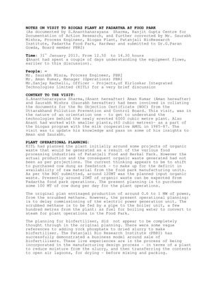
  • 7. POSSIBLE BLOCK DIAGRAM FOR BIOGAS PLANT AS PER LIMITED UNDERSTANDING OF S.ANANTHANARAYANA SHARMA BASED ON THE OBVERSATIONS ON 31 JANUARY 2013 Inlet tank Mixing tank Buffer tank BIOGAS DIGESTER DEGASSER SEPARATION UNIT FOR BIOFERTILISER METHANE GAS Holder Blowers SCRUBBER Scrubbed Methane to boiler