Download to read offline
![Water Valve Shutoff
WVS
Water Valve Shutoff
Monitors flooding from
leaking or broken water
line
Automatic control of
main water supply line
Form C Relay output for
external monitoring
devices
Visual and audible
status indicators
Automatic self testing
Covers large area when
used with multiple
sensors
Low voltage design with
battery backup
Product Specification PDF's
About PDF
GRI Water Valve Shutoff Product Specification PDF
GRI Water Valve Shutoff Instructions PDF
[Home] [Products] [What's New!] [Security Products] [Data Entry Peripherals] [Pushbutton Switches]
[Custom Engraved Keycaps] [Proximity Sensors] [Contact GRI] [About GRI]
file:///Z:/My Web Sites/grisk/specialty/water_valve_shutoff.html
Revised: Friday, September 13, 2013
Web design by The Computer Guy Copyright © 1997-2011](https://image.slidesharecdn.com/wvs-150603152733-lva1-app6891/85/GRI-WVS-Data-Sheet-1-320.jpg)
![Water Valve Shutoff
WVS
Water Valve Shutoff
Monitors flooding from
leaking or broken water
line
Automatic control of
main water supply line
Form C Relay output for
external monitoring
devices
Visual and audible
status indicators
Automatic self testing
Covers large area when
used with multiple
sensors
Low voltage design with
battery backup
Product Specification PDF's
About PDF
GRI Water Valve Shutoff Product Specification PDF
GRI Water Valve Shutoff Instructions PDF
[Home] [Products] [What's New!] [Security Products] [Data Entry Peripherals] [Pushbutton Switches]
[Custom Engraved Keycaps] [Proximity Sensors] [Contact GRI] [About GRI]
file:///Z:/My Web Sites/grisk/specialty/water_valve_shutoff.html
Revised: Friday, September 13, 2013
Web design by The Computer Guy Copyright © 1997-2011](https://image.slidesharecdn.com/wvs-150603152733-lva1-app6891/75/GRI-WVS-Data-Sheet-1-2048.jpg)
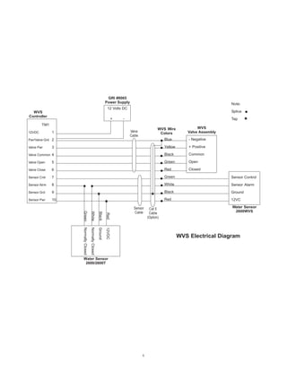
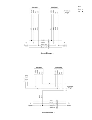
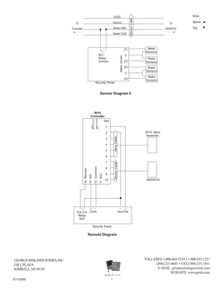

The document describes the G.R.I. Water Valve Shutoff System, which automatically shuts off the main water supply line when water is detected by sensors. The system includes an electronic controller that monitors multiple water sensors, controls an electronic water valve, and provides status indicators. When water is detected, the controller closes the valve and triggers an alarm. It can cover a large area when used with multiple sensors and has self-testing features to monitor operation.


